
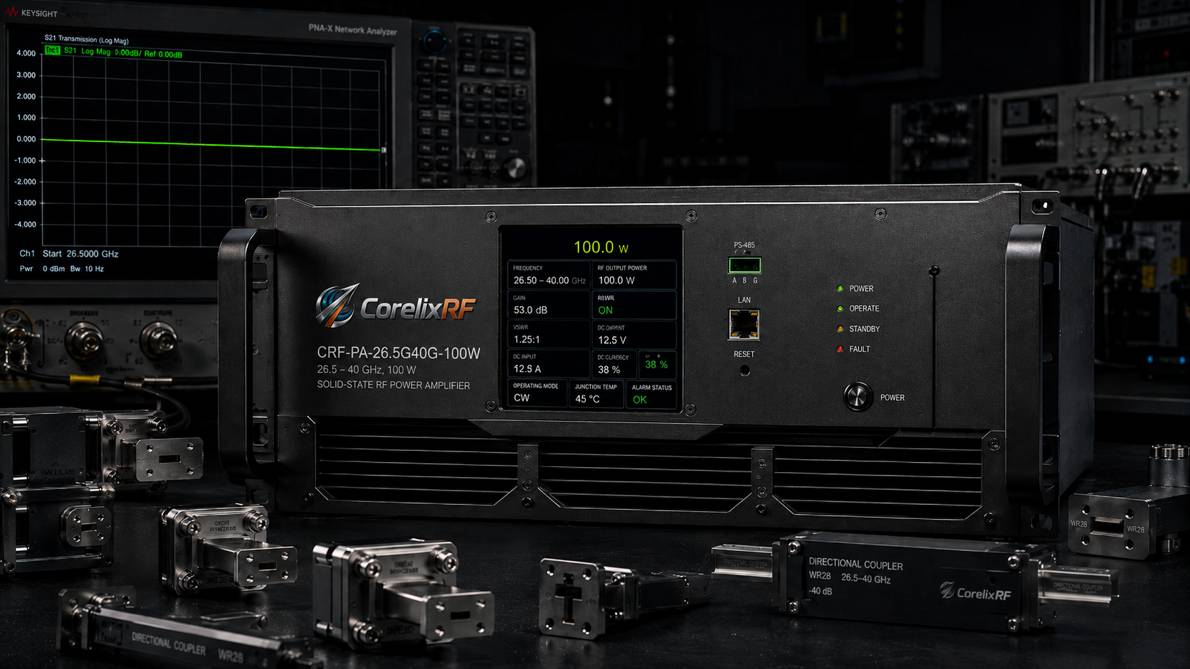
Engineers configure complex test benches seeking Ka-band radar validation constantly. They connect multiple cascaded components directly. Technicians run wideband sweeps across 26.5 GHz up through 40 GHz. A vector network analyzer display suddenly mimics a jagged roller coaster. You just wasted three days chasing ghost reflections frantically. A tiny calibration oversight destroys weeks spent prototyping electronic warfare systems. You sit staring blindly at flashing standing wave warnings. Your expensive prototype completely fails rigorous customer validation. Here lies a systematic method applying exact matching logic alongside ruggedized factory-direct hardware. We recommend our CRF-PA-26500M40000M-100W solid-state module. CorelixRF personnel manufacture military-grade radio frequency amplifiers continuously over thirty years. We understand exact physical hardware limitations inside real-world environments. Here’s the deal. I will explain precisely why cascading uncalibrated pads violently distorts signal integrity data. Let us reconstruct your broken measurement architecture immediately. We build dependable equipment serving serious procurement engineers demanding absolute physical reality. This article focuses strictly on Microwave Lab RF Front-End Construction principles.
Translate microwave lab RF front-end issues into amplifier platform choices
For microwave lab distortion, VSWR risk or gain stability problems, CorelixRF can review GaN amplifier class, 6-18 GHz options, RF front-end layout and test documentation before quotation.
1. What causes VNA curve collapse during high-frequency microwave laboratory testing?
High-frequency environments punish lazy engineering relentlessly. Microwave Lab RF Front-End Construction requires absolute precision constantly. Technicians frequently chain multiple attenuators together blindly. They attempt bringing high-power signals down toward safe analyzer input thresholds. This cascaded setup introduces massive impedance mismatches immediately. Each junction creates parasitic capacitance shifting phase responses unpredictably. High-frequency bands around 30 GHz amplify these tiny physical imperfections massively. Signals bounce between connector interfaces repeatedly causing chaos. These secondary waves recombine destructively against your primary signal path. You observe sudden drop-outs on your VNA screen instantly. We call this phenomenon curve collapse internally. Many novice operators blame their expensive testing equipment mistakenly. They send units back requesting unnecessary factory recalibration procedures. You might be wondering. Why does standard equipment fail here? Standard pads lack precise phase matching capabilities across wide bandwidths. Their VSWR compounds multiplicatively rather than additively during operation. Our factory analyzes these exact failure modes daily. We design components specifically preventing such reflective disasters. Proper architecture mandates specialized hardware matching networks always. Consider an automotive radar manufacturer experiencing false positive target detections continuously. They wasted weeks debugging software algorithms unnecessarily. A simple inspection revealed three cheap SMA attenuators cascaded before their receiver. We replaced those components utilizing a single precision directional coupler. Their system noise floor dropped dramatically restoring normal function. Another defense contractor noticed severe power fluctuations during salt fog chamber testing. Moisture penetrated poorly sealed coaxial connections exacerbating existing mismatch issues. We upgraded their feedlines utilizing pressurized waveguide components. True physical engineering solves problems software patches cannot fix.
2. How do cascaded uncalibrated attenuators distort gain flatness data?
Let us examine actual physics driving this frustrating distortion. S-parameters define microwave network behaviors entirely. Cascading two pads changes your combined transmission coefficient drastically. Reflected energy from pad two travels backwards along your transmission line. It hits pad one again creating complex standing waves. A portion reflects forward mixing with your main wave. This interaction generates periodic ripples across your frequency response graph. Engineers calculate maximum ripple error using complex voltage reflection coefficients mathematically: $Error = 20 \log_{10}(1 \pm |\Gamma_1| |\Gamma_2| |S_{21}|^2)$. Formulaic reality dictates total mismatch uncertainty heavily relies upon both source and load values. We see peak-to-peak ripples exceeding 3dB easily during standard verification. That margin completely ruins any serious Military-spec validation report. Your Microwave Lab RF Front-End Construction effort becomes totally worthless. What’s the real story? Uncalibrated pads possess wild phase variations across different frequency points. A 10dB pad might show 12dB attenuation at 35 GHz. Stacking three such components yields completely unpredictable nonlinear results. Engineers must utilize single high-power directional couplers instead. Alternatively they need fully matched precision attenuator blocks. We witnessed countless satellite communication teams fail certification due solely toward poor pad cascading habits. A recent aerospace client attempted validating a massive phased array antenna. They cascaded four separate pads protecting their sensitive spectrum analyzer. The resulting ripple masked critical side-lobe emission characteristics entirely. We calculated their mismatch uncertainty exceeding 4.5 decibels mathematically. Our team implemented a bespoke high-power termination loop rectifying their measurement errors. Physics demands respect regardless of your project budget constraints. You cannot cheat basic electromagnetic principles utilizing cheap shortcuts.
Mismatch Error Ripple Calculation Examples
| Component Cascade Setup | Return Loss (dB) | Est. Mismatch Error (dB) | System Impact |
| Single Calibrated Pad | 25 | 0.05 | Negligible distortion |
| Two Generic SMA Pads | 15 | 0.85 | Noticeable curve ripple |
| Three Cascaded Adapters | 10 | 2.50 | Severe data invalidation |
| Unmatched Load + Cable | 8 | 3.80 | Total test failure |
3. Why does link budget architecture demand precision front-end matching networks?
System integrators routinely underestimate upstream architecture planning requirements. Link budgets calculate every single decibel gained or lost carefully. Microwave Lab RF Front-End Construction demands tight control over these variables. A sloppy front-end introduces noise figures cascading downstream irreparably. Receiving chains cannot amplify signals buried beneath thermal noise floors. We evaluate bill-of-materials choices rigorously during initial design phases. Procurement teams often select cheap generic components initially. They quickly discover severe performance degradation during integration testing. Replacing buried components costs ten times more than buying proper hardware upfront. Ready for the good part? Proper matching networks stabilize impedance presented toward your high-power amplifier. This prevents load-pull effects from altering your device gain characteristics. An amplifier driving a mismatched load performs significantly worse than datasheet specifications claim. CorelixRF designs focus heavily upon maintaining strict 50-ohm environments internally. We guarantee our modules deliver consistent power regardless of minor external load fluctuations. This philosophy saves defense contractors millions during field deployments. We analyzed a drone jammer prototype dropping output power unexpectedly. Their procurement department substituted precision isolators substituting low-cost commercial variants. Antenna impedance shifted radically during flight maneuvers altering amplifier operating points. We re-engineered their output stage implementing strict broadband matching topologies. The jammer maintained full output power during aggressive aerial maneuvers flawlessly. Proper component selection prevents catastrophic failures occurring during critical missions. Upstream thinking saves downstream troubleshooting delays inevitably.
4. What hardware specifications define the CRF-PA-26500M40000M-100W amplifier?
Our proprietary hardware solves these exact integration nightmares definitively. The CRF-PA-26500M40000M-100W module covers an expansive 26,500 MHz through 40,000 MHz range. It delivers a guaranteed 100 watts of continuous output power. This unit provides 53 decibels of small signal gain. We maintain a strict gain flatness tolerance bounded within ±8 decibels. Operators can utilize an integrated adjustable gain control span reaching 15 decibels. The input voltage standing wave ratio remains below 2:1 consistently. We require a standard AC 380V three-phase power supply running at 50/60Hz. This is where it gets interesting. Harmonic distortion stays firmly suppressed below -10 dBc. Spurious emissions remain undetectable below -60 dBc. We package this massive capability inside a rugged 5U rackmount chassis. The total system weight equals exactly 50 kilograms. This equipment suits electronic warfare and radar simulation tasks perfectly. We built this specific architecture targeting serious procurement engineers exclusively. Your Microwave Lab RF Front-End Construction deserves true industrial-grade power sourcing. A major research university required highly stable signal sources driving plasma chambers. Their existing commercial amplifiers kept tripping internal thermal breakers constantly. We installed our 5U rackmount solution providing massive thermal headroom. They ran continuous 72-hour experiments without encountering single hardware fault. Another client needed precise power leveling capabilities testing sensitive satellite receivers. Our adjustable gain control provided exact stimulus levels required for receiver saturation testing. Factory-direct specifications represent guaranteed performance metrics rather than marketing hopes.
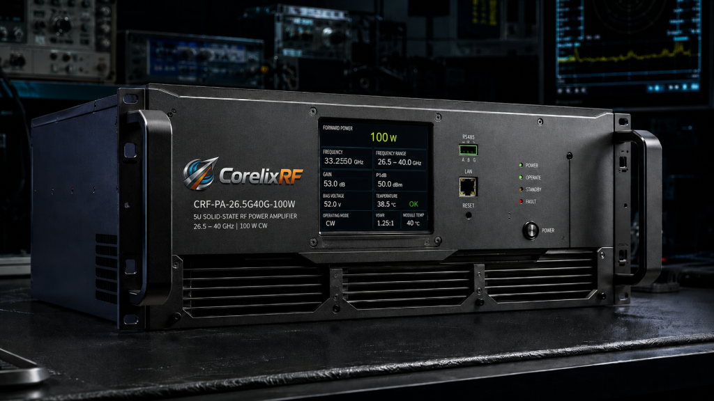
CRF-PA-26500M40000M-100W Core Parameters
| Parameter | Minimum Value | Typical Value | Maximum Value |
| Frequency Range | 26,500 MHz | — | 40,000 MHz |
| Small Signal Gain | 53 dB | — | — |
| Rated Output Power | 100 W | — | — |
| Power Consumption | — | 2500 W | — |
| Operating Temp | 0 °C | — | 50 °C |
5. How does GaN technology address thermal dissipation in 5U rackmount structures?
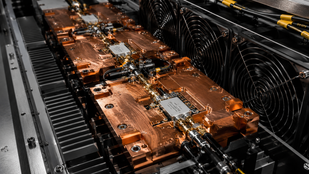
Gallium Nitride semiconductors operate exceptionally well under extreme thermal stress. We utilize advanced GaN-on-SiC die attachments inside our output stages. This material handles significantly higher power densities than legacy Gallium Arsenide components. Our CRF-PA-26500M40000M-100W consumes roughly 2500 watts of raw AC power. Generating 100 watts of RF energy produces substantial waste heat. We must extract this thermal load efficiently from microscopic transistor junctions. You might be wondering. How do we prevent thermal runaway inside a closed 5U chassis? CorelixRF engineers implement massive custom-machined copper baseplates acting as primary heat spreaders. High-velocity industrial fans force ambient air across tightly spaced aluminum cooling fins. This active air cooling method maintains safe operating temperatures between 0 and 50 degrees Celsius. We mandate unobstructed airflow paths during your facility installation process. Thermal management directly dictates long-term reliability for continuous wave applications. Your Microwave Lab RF Front-End Construction requires robust environmental controls always. Heat destroys poorly designed electronics rapidly. An electronic warfare contractor mounted our amplifier inside an unventilated vehicle compartment. Internal ambient temperatures reached 65 degrees Celsius during desert testing scenarios. Our internal thermal protection circuits gracefully reduced output power preventing catastrophic junction meltdowns. We subsequently advised them modifying their rack airflow ducting properly. They installed dedicated exhaust fans pushing hot air outside their vehicle hull. The amplifier resumed providing full 100-watt continuous output power flawlessly. Rugged engineering buys time when integrators make thermal planning errors.
6. What protection mechanisms prevent standing wave ratio (VSWR) failures?
High power microwave amplifiers face constant danger from severe load mismatches. An operator might accidentally disconnect a waveguide flange during active transmission. That 100-watt forward wave instantly reflects backwards toward our fragile output transistors. This catastrophic event vaporizes unprotected silicon junctions within microseconds. Our CRF-PA-26500M40000M-100W incorporates incredibly fast localized protection circuitry. We sample forward and reverse power levels continuously using internal directional couplers. Here’s the deal. A dedicated microcontroller monitors these voltage levels constantly. It interrupts DC bias currents instantly if VSWR exceeds safe programmed thresholds. We also implement redundant over-voltage and over-temperature safety interlocks. The system shuts down automatically before physical damage occurs. It illuminates front panel warning indicators clearly. Operators must manually reset the unit after correcting external load faults. This philosophy prevents expensive factory repair cycles entirely. We design our equipment assuming end-users make simple operational mistakes occasionally. Ruggedness defines true Microwave Lab RF Front-End Construction quality. A junior technician activated a test bench forgetting terminating an antenna port. Our amplifier detected an infinite VSWR condition shutting down within milliseconds. We saved a forty-thousand-dollar module from total destruction instantly. Another facility experienced massive power grid voltage spikes during a thunderstorm. Our over-voltage protection clamped internal power rails saving delicate RF driver stages. We build equipment surviving harsh realities rather than sterile laboratory conditions. Protection mechanisms represent non-negotiable features regarding high-power B2B hardware.
Hardware Protection Matrix
| Fault Condition | Detection Method | System Response | Recovery Action |
| Load Mismatch (VSWR > 3:1) | Reverse power sensing | Instant RF mute | Manual fault reset |
| Over-Temperature (>65 °C) | Baseplate thermistors | DC bias shutdown | Auto-resume upon cooling |
| Over-Voltage Input | Supply rail monitoring | Crowbar circuit trip | Hardware inspection required |
| Over-Drive (Input > 3dBm) | Input coupler sensing | Variable attenuator pad | Reduce signal generator output |
7. Why are WR28 waveguide outputs mandatory for 40 GHz signal integrity?
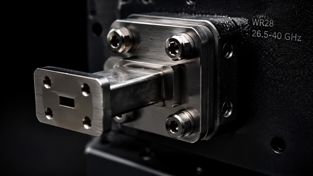
Coaxial connectors struggle handling high power levels at millimeter-wave frequencies. A standard 2.92mm female connector works fine for our low-power input port. It cannot survive 100 watts of continuous RF energy at 40 GHz. The center pin simply melts due toward excessive skin effect resistive heating. We mandate WR28 rectangular waveguide interfaces for all high-power output connections. Waveguides eliminate central conductors entirely. They transport electromagnetic energy through hollow metallic tubes efficiently. This transition drastically reduces insertion loss across our entire operating bandwidth. What’s the real story? Waveguides also provide natural high-pass filtering characteristics. They suppress low-frequency out-of-band spurious emissions inherently. Mating WR28 flanges requires precise mechanical alignment during installation. Engineers must torque connecting bolts evenly preventing microscopic gaps. Even tiny misalignments cause severe RF leakage and localized hot spots. Precision mechanical assembly dictates successful Microwave Lab RF Front-End Construction directly. We supply detailed dimensional drawings ensuring flawless rack integration always. A radar integrator attempted using flexible coaxial cables pushing 50 watts Ka-band power. The cable dielectric melted causing a direct internal short circuit. We replaced their entire output run utilizing rigid WR28 copper waveguide sections. System losses dropped by two full decibels immediately improving range resolution. Another client failed emission compliance testing due toward low-frequency harmonic leakage. We swapped their coaxial output utilizing a WR28 interface leveraging its natural cutoff frequency. They passed their compliance audit flawlessly without needing extra discrete filters. Mechanical interfaces determine electrical performance absolutely.
Millimeter-Wave Connector Power Handling Limits
| Connector Type | Frequency Limit | Continuous CW Power Rating @ 40GHz | Primary Failure Mode |
| SMA Female | 18 GHz | Not Rated | Center pin melting |
| 2.92mm Female | 40 GHz | < 5 Watts | Dielectric breakdown |
| 2.4mm Female | 50 GHz | < 3 Watts | Resistive heating |
| WR28 Waveguide | 40 GHz | > 500 Watts | Flange arcing (if loose) |
8. How do RS485 and LAN interfaces streamline B2B system integration?
Modern test benches require seamless automated control from central supervisory computers. Manual front panel knobs lack sufficient speed for complex radar simulation routines. We equip the CRF-PA-26500M40000M-100W with standard RS485 and Ethernet LAN interfaces. System integrators write custom Python scripts talking directly with our hardware. They adjust gain levels dynamically simulating moving target cross-sections. Ready for the good part? Our digital architecture supports full SCADA network integration flawlessly. Remote monitoring software reads internal temperatures and output power levels continuously. This capability proves strictly necessary for isolated antenna test ranges. Engineers sitting miles away monitor amplifier health without leaving their control rooms. We provide comprehensive command protocols matching industry standard syntax. Defense contractors demand this level of remote telemetry for classified projects. Your Microwave Lab RF Front-End Construction must incorporate automated diagnostics from day one. We refuse building obsolete manually operated hardware platforms. An overseas aerospace agency required controlling twelve amplifiers simultaneously during phased array testing. They utilized our LAN interface sending synchronized UDP packets adjusting phase and amplitude. Manual adjustment would require weeks completing a single radiation pattern measurement. Our digital interface reduced their entire test cycle from weeks toward hours. Another facility experienced intermittent air conditioning failures during overnight automated testing. Our amplifier reported rising temperatures via SNMP traps triggering automatic facility alarms. Remote telemetry prevents silent catastrophic failures during unattended operational cycles. Digital integration defines modern RF hardware utility.
Control Interface Protocol Options
| Interface Type | Primary Use Case | Maximum Cable Length | Latency Characteristic |
| Front Panel Knobs | Manual lab debugging | N/A | Human limited |
| RS485 Serial | Legacy SCADA systems | 1200 meters | Moderate (~10ms) |
| Ethernet LAN | Automated Python arrays | 100 meters | Extremely low (<1ms) |
| Optional GPIB | Legacy automated test | 20 meters | Standard IEEE-488 |
9. What specific calibration routines guarantee flat response curves?
Achieving accurate measurements requires rigorous vector network analyzer calibration discipline. You must establish reference planes exactly at your final device input terminals. We strongly recommend performing full two-port short-open-load-through procedures regularly. Operators must use precision mechanical calibration kits matching their exact connector types. Electronic calibration modules offer convenience but sometimes lack ultimate millimeter-wave accuracy. This is where it gets interesting. You must mathematically de-embed any intermediate cables or adapters from your final results. VNA firmware calculates complex error terms correcting systematic directivity and tracking errors. We test our CRF-PA-26500M40000M-100W amplifiers using highly controlled metrology-grade environments exclusively. We supply baseline S-parameter files for project review purposes upon request. Comparing your localized measurements against our factory data reveals any test bench flaws instantly. Proper calibration separates amateur setups from professional Microwave Lab RF Front-End Construction efforts. Bad data remains worse than no data at all. A university lab complained our amplifier fell short regarding specified gain flatness. We reviewed their setup discovering they used uncalibrated test cables connecting their VNA. Applying proper calibration mathematically removed three decibels of cable ripple instantly. Our amplifier met factory specifications perfectly once they corrected their measurement methodology. Another client struggled matching our phase data against their system models. We supplied exact S2P files mapping our device characteristics enabling perfect digital twin simulation. Precision testing requires meticulous attention regarding every single measurement detail.
10. What are final engineering verdicts for RF front-end architectures?
We discussed complex physical realities governing high-frequency testing environments thoroughly today. Cascaded mismatched attenuators destroy measurement integrity through severe standing wave generation completely. Proper system architecture demands ruggedized industrial equipment like our CRF-PA-26500M40000M-100W amplifier. We manufacture these 100-watt continuous wave monsters targeting serious B2B clients exclusively. Our GaN technology survives brutal thermal and electrical abuse reliably. Here’s the deal. You must respect physics when building your Ka-band validation platforms. Stop wasting time chasing ghost reflections caused by cheap generic components. Implement proper waveguide transitions and automated LAN control protocols strictly. Connect with CorelixRF engineering teams right now regarding your specific integration requirements. We provide unvarnished truth regarding RF power generation limitations and capabilities. Quality Microwave Lab RF Front-End Construction requires specialized knowledge from experienced factory sources. Stop guessing and start measuring accurately today. We witnessed companies lose multi-million dollar defense contracts failing basic RF compliance audits. They compromised their test infrastructure utilizing substandard mismatched commercial grade attenuators. Our team replaced their entire bench utilizing precision matched waveguide couplers and robust amplifiers. They successfully demonstrated their radar prototype securing full government funding immediately afterwards. Industrial grade hardware pays massive dividends when performing critical path engineering tasks. Contact our technical sales department acquiring comprehensive performance datasheets today. We deliver Engineering Truth supporting your most demanding integration projects.
FAQ Section
Q1: What is Microwave Lab RF Front-End Construction?
Microwave Lab RF Front-End Construction refers toward planning and assembling high-frequency components before testing receivers. Engineers select matched amplifiers, directional couplers, and waveguide transitions specifically preventing signal distortion. Proper construction minimizes impedance mismatches guaranteeing accurate Vector Network Analyzer measurement data consistently.
Q2: How does cascaded attenuator mismatch work?
Cascaded attenuator mismatch happens when multiple uncalibrated pads connect sequentially. Radio frequency energy reflects backwards between connector interfaces generating standing waves. These reflections combine destructively across wide bandwidths causing severe gain flatness ripple errors during high-frequency measurements.
Q3: Why select the CRF-PA-26500M40000M-100W for Ka-band radar testing? The CRF-PA-26500M40000M-100W provides 100 watts of continuous RF power across 26.5 GHz through 40 GHz. It features integrated VSWR protection circuits preventing transistor destruction during accidental load mismatches. This rugged 5U rackmount design survives harsh laboratory testing environments flawlessly.
Q4: How does WR28 waveguide improve millimeter-wave signal integrity?
WR28 waveguide transports electromagnetic energy through hollow rectangular metal tubes eliminating central conductors. This topology drastically lowers insertion loss preventing resistive heating failures common among coaxial cables exceeding 50 watts. Waveguides provide superior impedance matching reducing return loss errors significantly.
Q5: What is the proper calibration method avoiding VNA curve collapse?
Engineers must perform full two-port short-open-load-through mechanical calibration routines directly at their final device terminals. They must mathematically de-embed any intermediate test cables utilizing S-parameter error correction algorithms. This discipline isolates true amplifier performance separating it from random test bench reflections.