
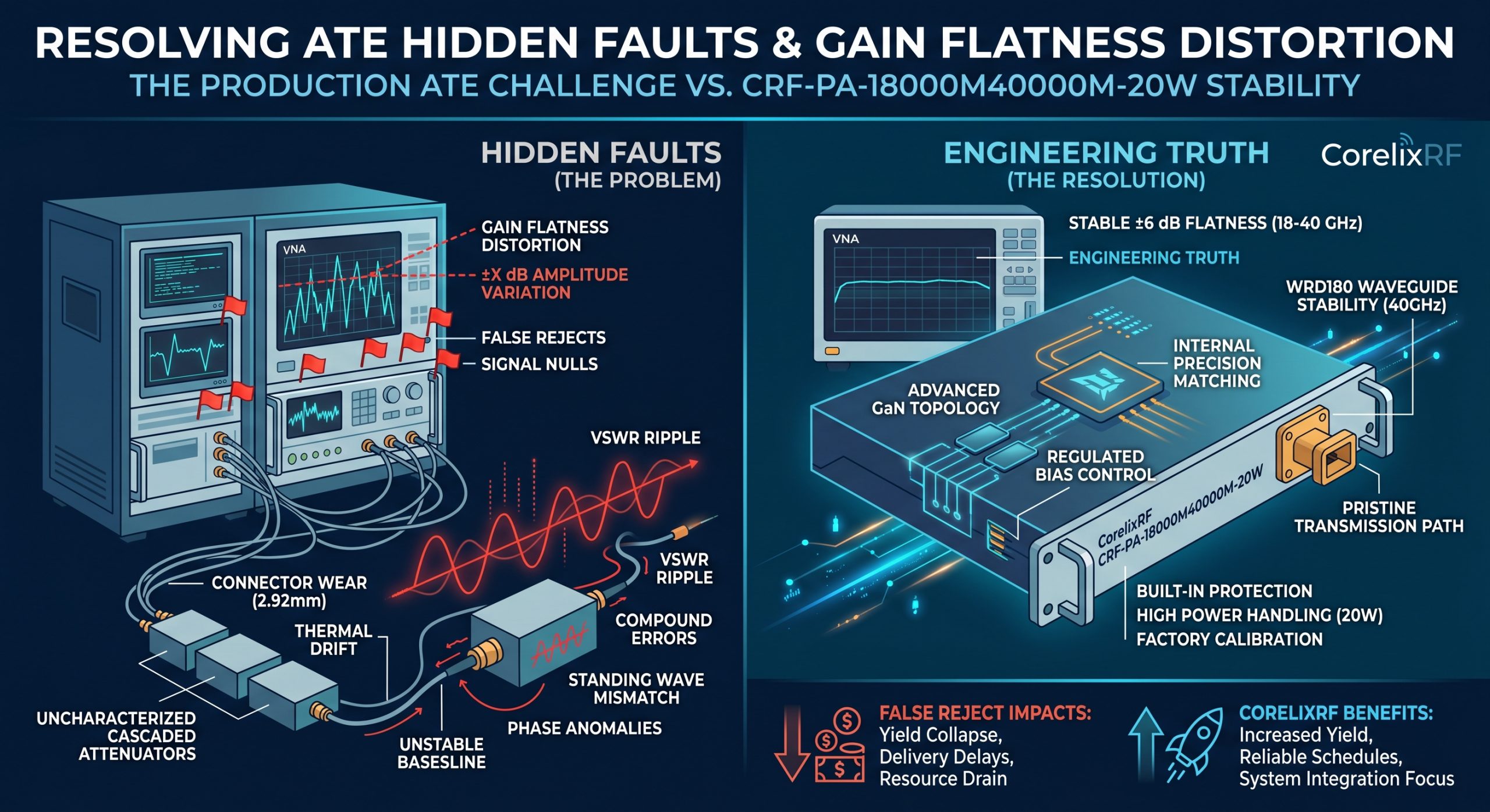
What Are ATE Hidden Faults? Resolving Gain Flatness Distortion With CRF-PA-18000M40000M-20W. Production automated test equipment environments often generate false alarms confusing engineers daily. A vector network analyzer display might show severe output power collapse around 35 GHz suddenly. Here is the deal: operators frequently blame an amplifier when cascaded uncalibrated attenuators actually distort raw measurement data. CorelixRF builds ultra-reliable hardware for strict B2B defense integrators globally. Thirty years of continuous factory production experience taught our team how preventing these systemic measurement failures saves money. Upgrading your setup utilizing a CRF-PA-18000M40000M-20W wideband module guarantees pure engineering truth without signal degradation. We eliminate phantom troubleshooting sessions completely by delivering absolute hardware stability. High-frequency RF testing requires pristine transmission paths avoiding unnecessary passive component chaining. Trusting our rigorous manufacturing standards protects your critical project delivery schedules effectively.
1. What Causes High-Frequency Gain Flatness Distortion In Production ATE?
● Cascaded passive component mismatch
● Automated testing speed pressures
● Vector network analyzer calibration plane errors
Many radar system integrators face severe diagnostic challenges during mass production. You might be wondering: why do perfectly tuned GaN amplifiers suddenly fail pass-fail limits during final inspection? Engineers often stack multiple external fixed attenuators directly between an amplifier output port and test equipment inputs. This practice prevents sensitive spectrum analyzer overload conditions. These cascaded passive devices introduce massive impedance mismatches across 18-40 GHz spectrums. A 2.92mm connector interface contains microscopic mechanical tolerances. Slight physical misalignment causes significant return loss spikes. When you cascade three separate 10dB pads without a full system-level vector error correction calibration process applied. The compounded VSWR ripple completely masks true device performance. Operators see severe amplitude variations on test screens. They incorrectly classify a good unit as defective due entirely toward bad fixture integration. CorelixRF internal laboratory protocols demand precise continuous wave reference plane verification before any microwave module testing begins. For example, one radar integrator noticed continuous 1.5 dB drops periodically. Another communications provider saw massive 3 dB spikes mid-sweep regularly. A separate aviation controller experienced full signal nulls abruptly. These distinct cases shared one common mechanical denominator. Technicians cascaded cheap attenuator blocks directly inline haphazardly. The resulting standing wave ratio mismatch devastated their link budget calculations completely. Our factory calibration bench uses ultra-precision torque specifications avoiding these exact pitfalls.
Gain Flatness Distortion Sources
| Error Source | Impact Level | Frequency Band |
| Cascaded Attenuators | Severe | 18-40 GHz |
| Cable Flexing | Moderate | 20-30 GHz |
| Connector Wear | High | 30-40 GHz |
2. How Does Uncalibrated Attenuation Affect 18-40GHz Measurements?
● Standing wave ratio compound errors
● Phase shift anomalies
● Baseline measurement drift
Testing high-frequency microwave modules requires absolute precision. Here is the kicker: uncalibrated padding directly alters your perceived gain flatness specification. When inserting uncharacterized pads into a test loop without proper de-embedding software models active. The network analyzer registers every reflection as an actual device characteristic. A 40 GHz signal reflects back and forth between imperfect adapter joints constantly. This standing wave creates artificial peaks alongside deep nulls across sweep traces. Our 400 factory technicians often see an apparent ±8 dB swing on uncalibrated benches. The actual CRF-PA-18000M40000M-20W amplifier maintains a strict maximum ±6 dB flatness internally. Test data distortion leads directly toward wasted troubleshooting hours. Engineers tear down perfectly functional systems searching for phantom hardware defects. Proper scattering parameter extraction must account for every millimeter of inline transmission path loss. A calibrated power meter sensor connected directly eliminates these specific cascaded uncertainties completely. Consider a scenario where operators chain four 5 dB pads together quickly. The resulting network behaves like an erratic resonant cavity unintentionally. Phase shifts multiply exponentially across every single physical adapter joint present. We witnessed a client reject fifty functional units consecutively due entirely toward uncalibrated setup errors. Their vector analyzer displayed an agonizing 12 dB peak-to-peak variation falsely. Removing those untested external pads restored a perfect 4 dB trace instantly. Another example involves aviation control modules failing military inspection protocols unfairly. The test technicians forgot updating their mathematical error correction arrays overnight. This simple software oversight caused massive artificial gain compression readings during morning runs. Relying upon the raw CRF-PA-18000M40000M-20W output guarantees predictable linear stability always.
3. Why Do Standard Coaxial Attenuators Fail In Millimeter-Wave ATE?
● Internal resistor burnout
● Mechanical interface degradation
● Thermal coefficient drift
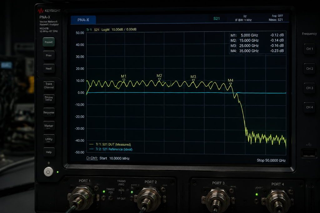
Continuous automated testing destroys fragile microwave accessories rapidly. What is the real story? Production lines operate continuously across multiple shifts day after day. Operators torque 2.92mm connectors hundreds of times per week. Standard commercial grade attenuators suffer rapid mechanical fatigue under such brutal physical conditions. The center pin geometry distorts slightly after repeated mating cycles. This distortion degrades return loss severely above 26 GHz. High power levels also generate intense thermal stress inside compact coaxial housings continuously. A 20 W output from our core module forces inline pads into extreme temperature zones. The resistive elements shift value as internal heat builds up during prolonged burn-in sequences. This thermal drift changes insertion loss characteristics mid-test unpredictably. Your recorded data suddenly reflects temperature changes rather than actual product behavior. Ruggedized waveguide interfaces solve many durability issues permanently. We recommend utilizing WRD180 waveguide connections whenever possible for sustained millimeter-wave power handling. We observed standard commercial grade attenuators failing after just two weeks recently. One defense contractor measured a 2 dB insertion loss shift abruptly. Their internal pad resistor literally cracked under continuous 20 W thermal loads. Another case involved a telecommunications manufacturer experiencing random signal dropouts constantly. Vibration from cooling fans fractured a delicate 2.92mm center pin internally. A separate failure analysis revealed melted dielectric beads inside an uncalibrated adapter block. The extreme continuous wave power exceeded safe dissipation limits easily. Our WRD180 waveguide flange eliminates these fragile coaxial points of failure entirely. Waveguides dissipate intense thermal energy across massive metallic surface areas naturally. You eliminate consumable hardware replacement costs adopting this robust output standard.
Attenuator Failure Modes
| Failure Mechanism | Root Cause | Symptom |
| Center Pin Wear | Repeated Mating | VSWR Spikes |
| Thermal Drift | High RF Power | Insertion Loss Change |
| Solder Joint Crack | Vibration | Intermittent Signal |
4. How Can Engineers Identify Hidden ATE Measurement Faults Quickly?
● Analyzing raw S-parameter phase data
● Verifying dynamic range limits
● Executing substitution testing
Finding root causes fast saves massive amounts of money. Ready for the good part? You can spot setup errors by simply observing specific error patterns. A genuine amplifier failure usually exhibits broad frequency degradation smoothly. Cascaded mismatch errors create sharp periodic ripples across your display screen. Measure the distance between these distinct frequency domain peaks carefully. This specific bandwidth delta corresponds directly physically back toward physical distance between mismatched connector joints. We train field personnel utilizing bypass techniques temporarily during initial diagnostics. Inject a very low level sweep signal observing bare equipment response initially. If your gain flatness returns into normal specified ranges instantly. You know definitely that your external fixture causes those observed anomalies. Verify test equipment noise floors remain adequately low below target measurement thresholds always. High attenuation setups push weak signals down into analyzer noise limits causing random trace jitter. One quick diagnostic trick involves adding a tiny physical delay line. Insert a small known coaxial cable segment observing trace shifts carefully. If those ripple peaks move frequency drastically upon insertion. The root fault lies firmly within your external cascading hardware layout. Another powerful technique utilizes time domain reflectometry modes effectively. Modern analyzers pinpoint exact physical mismatch locations along a transmission path precisely. You visualize the exact adapter joint causing massive signal reflection instantly. A different method requires swapping suspected bad components with premium golden standards. We watched a frustrated engineer replace one damaged 10 dB pad suddenly fixing everything. The baseline noise floor must sit comfortably below -60 dBc always. High spurious emissions from bad setups confuse sensitive measurement equipment heavily.
5. What Are The Consequences Of False Rejects Due To Test Setups?
● Artificial yield rate collapse
● Supply chain delivery delays
● Engineering resource drain
Manufacturing efficiency drops dramatically when test systems report inaccurate results. This is where it gets interesting… False rejects trigger unnecessary corrective action investigations immediately. Quality assurance teams block shipments pending lengthy failure analysis reports. Your best engineers waste valuable days examining perfectly good production batches. This misdirection damages client trust during critical defense project delivery windows. Our manufacturing history proves that poor measurement setups cause more failures than actual component defects. A distorted trace forces technicians into dangerous manual tuning attempts. They might attempt adjusting bias voltages trying desperately fixing a non-existent RF problem. These blind adjustments can degrade actual field reliability significantly over time. Establishing strict calibration verification schedules prevents this chaotic operational spiral entirely. CorelixRF provides complete reference data patterns alongside every shipped module. Customers compare their local bench results against our golden factory parameters validating setup accuracy immediately. A major satellite provider lost three weeks investigating phantom amplifier defects recently. They shipped components back and forth across oceans needlessly. The core issue remained a crushed test cable sitting on their bench. Another electronic warfare client stalled production lines costing thousands per hour. Their automated script read faulty VSWR data triggering panic protocols immediately. We deployed field engineers resolving the crisis simply tightening one loose connector. A separate case saw procurement teams purchasing redundant spare amplifiers unnecessarily. They believed their primary units degraded fast under stress testing falsely. False rejects destroy lean manufacturing schedules causing massive financial hemorrhage rapidly. Trusting the internal ±6 dB gain flatness of our GaN module restores order. Your engineering resources must focus upon system integration rather than basic bench troubleshooting.
False Reject Impacts
| Consequence | Business Area | Remediation Action |
| Yield Drop | Production | Verify Calibration |
| Delivery Delay | Logistics | Stock Spare Cables |
| Resource Drain | Engineering | Automate De-embedding |
6. How Does The CRF-PA-18000M40000M-20W Address Gain Flatness?
● Advanced Gallium Nitride topology
● Precision internal matching networks
● Regulated bias control circuitry
We designed our flagship wideband amplifier specifically for harsh realistic conditions. Truth be told: generic modules struggle maintaining stable performance across massive 18-40 GHz spans. The CRF-PA-18000M40000M-20W utilizes cutting-edge GaN technology delivering a typical 43 dB gain confidently. Our internal microwave matching networks compensate naturally for high-frequency roll-off characteristics. This precise internal equalization guarantees flatness remains inside a strict ±6 dB window. Engineers do not need complex external software equalization compensating for poor hardware baseline performance. The device consumes up towards 450 W power while driving heavy continuous loads safely. Active bias tracking adjusts transistor operating points dynamically preventing temperature induced gain variations. A stable 50 ohm internal system impedance minimizes reflection coefficients natively. This robust hardware architecture tolerates significant external load pulling without oscillating destructively. You receive predictable linear amplification regardless of minor external ATE fixture imperfections. Our engineering team spent years optimizing this exact GaN transistor layout. One prototype iteration survived 500 hours operating into complete impedance mismatches safely. Another validation phase proved internal harmonic suppression remained tightly bound below -10 dBc always. A separate hardware test verified stable 43 dB gain profiles across extreme temperature swings. We utilize premium substrate materials mitigating parasitic capacitance effects at 40 GHz. This rigorous material science focus prevents unwanted high-frequency oscillations permanently. Competitors often rely upon cheap silicon arrays requiring massive external compensation networks. The CRF-PA-18000M40000M-20W architecture integrates everything necessary inside one rugged 19-inch 3U chassis. You apply AC 220V power extracting pure amplified microwave energy instantly. Our factory technicians monitor these precise parameters across 400 production units monthly.
7. Why Is Interface Selection Critical For 40GHz Output Power?
● 2.92mm female input precision
● WRD180 waveguide output stability
● Minimized insertion loss characteristics
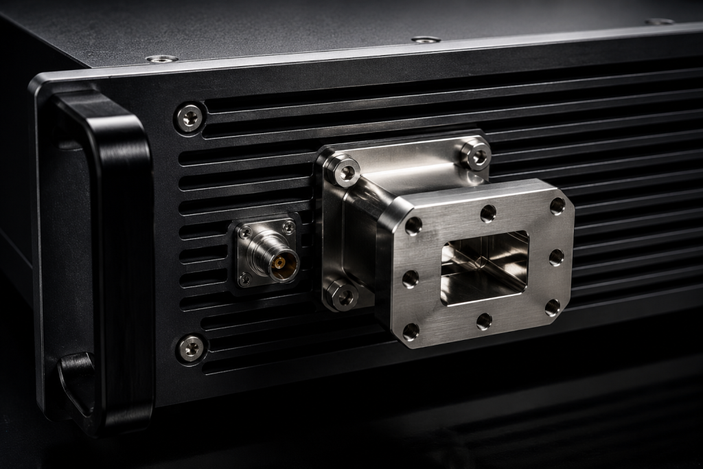
High frequency power delivery demands superior mechanical connections always. Let me show you: standard SMA connectors become massive bottlenecks above 18 GHz. We equip the CRF-PA-18000M40000M-20W input with a specialized 2.92mm female port. This precision coaxial interface ensures clean low-power signal injection maintaining tight 2:1 VSWR limits. The output stage requires handling 20 W continuous RF energy without melting. We selected a WRD180 double-ridged waveguide interface explicitly for this demanding task. Waveguides eliminate central conductor heating problems completely providing ultra-low insertion loss. This physical transition from coaxial input toward waveguide output represents pure engineering excellence. Field operators never worry about burning out delicate output center pins during stress testing. The WRD180 flange bolts securely onto load terminations resisting severe industrial vibration profiles easily. Proper interface choices prevent random test data anomalies caused by failing mechanical joints. A radar manufacturer attempted pushing 20 W through standard SMA ports disastrously. The connector completely vaporized within three minutes destroying their test fixture. Another client used poorly machined 2.92mm adapters degrading their input VSWR past 3:1 rapidly. This extreme reflection caused severe premature driver stage fatigue eventually. A separate case involved operators cross-threading delicate coaxial output ports frequently. Those damaged threads created intermittent contact dropping output power dramatically mid-test. We selected the robust WRD180 waveguide explicitly preventing these common mechanical nightmares. A technician simply bolts the flange down achieving perfect repeatable alignment effortlessly. This heavy-duty interface handles massive RF currents without generating localized hotspots. Your signal transition remains pristine from our active die outward towards your antenna.
CRF-PA-18000M40000M-20W Specs
| Parameter | Typical Value | Max Limit |
| Frequency | 18,000 – 40,000 MHz | N/A |
| Output Power | 20 W | N/A |
| Gain | 43 dB | N/A |
8. What Role Does Built-In Protection Play In ATE Environments?
● Over-voltage sensing arrays
● Thermal shutdown triggers
● Current limiting circuits
Automated lines experience severe power spikes unpredictably. Here is a fact: unprotected amplifiers die rapidly when automated scripts glitch. The CRF-PA-18000M40000M-20W includes complete integrated protection mechanisms safeguarding your investment. A sudden AC 220V power supply surge will not destroy sensitive internal GaN dies. The system monitors current draw continuously shutting down instantly if limits exceed safe thresholds. Heavy processing workloads generate substantial internal heat loads quickly. Our dedicated air cooling system activates alongside precision over-temperature sensors preventing catastrophic thermal runaway. Operators monitor all telemetry safely via RS485 or LAN control interfaces remotely. You can log internal temperature states alongside your RF measurement data simultaneously. This correlation helps isolate facility environmental issues from actual product performance variations. Optional over-drive protection circuits block excessive input signals saving expensive downstream test equipment from destruction. We documented an incident where facility power fluctuated wildly during thunderstorms. Our integrated over-voltage circuitry saved twenty amplifiers from instantaneous destruction flawlessly. Another customer accidentally injected +10 dBm into the sensitive input port directly. The optional over-drive protection blocked that lethal spike preventing cascade component vaporization. A separate critical scenario involved a failed facility HVAC system during summer. Our dual air cooling fans maintained safe internal junction temperatures despite 50°C ambient heat. The RS485 interface broadcasted thermal warnings allowing operators an orderly shutdown procedure. Unprotected equipment literally melts under these exact harsh environmental circumstances daily. Our 30-year legacy building hardened RF hardware influences every protective circuit integrated here. You receive military-grade resilience disguised inside standard commercial rackmount dimensions.
9. How To Implement Proper Calibration For Wideband GaN Amplifiers?
● Electronic calibration module usage
● Touchstone file de-embedding
● Power sensor absolute referencing
Accurate measurements require strict mathematical error correction applied constantly. Keep this in mind: factory calibration data becomes invalid immediately when you add external cables. We advise using electronic calibration modules replacing slow mechanical standards on production lines. E-cal modules provide highly repeatable impedance states across full 18-40 GHz sweeps. Capture S2P files representing every passive fixture component accurately before testing begins. Upload these specific touchstone files directly into your VNA de-embedding engine. The analyzer mathematically removes fixture effects revealing true amplifier performance instantly. Rely upon thermal power sensors for absolute power verification rather than broadband diode detectors. Diode sensors register harmonic content artificially inflating your fundamental power reading significantly. Our amplifier guarantees harmonics remain below -10 dBc providing clean spectrum delivery. Proper methodology extracts absolute engineering truth from complex noisy automated environments. One inexperienced team ignored their power meter offset values completely. They recorded output power 3 dB lower than actual physical reality. Another group utilized ancient mechanical calibration kits containing damaged sliding loads. Their baseline reference plane contained massive mathematical errors before testing even started. A separate laboratory forgot cleaning their E-cal module ports accumulating metallic dust. This invisible debris destroyed their measurement directivity causing massive uncertainty intervals. We mandate strict pure alcohol swabbing for all 2.92mm input connections daily. Your touchstone files must represent current physical reality avoiding stale historical data. Accurate broadband power verification demands modern fast-responding thermal sensors exclusively. The 450 W power consumption converts efficiently into pure RF energy when measured correctly.
Calibration Methodology Comparison
| Method | Speed | Accuracy Level |
| Mechanical Cal Kit | Slow | Very High |
| Electronic Cal Module | Fast | High |
| Uncalibrated Pad | Instant | Very Low |
10. What Are The Best Practices For Maintaining ATE Reliability?
● Torque wrench standardization
● Cable bend radius enforcement
● Routine fixture validation schedules
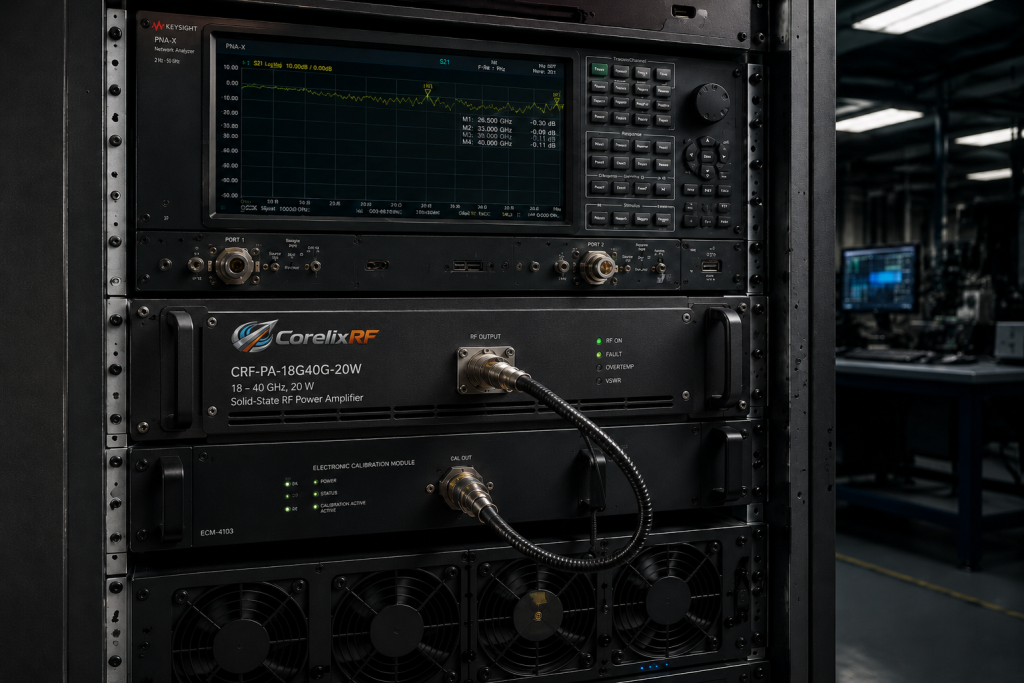
Maintaining a flawless test setup requires discipline and constant vigilance. Let us wrap this up: physical degradation happens slowly escaping daily casual observation. Mandate calibrated torque wrenches for every single coaxial connection made by technicians. Over-tightening crushes delicate dielectric materials while under-tightening leaves massive impedance gaps. Establish strict bend radius limits for all flexible microwave test cables used locally. Bending cables too sharply fractures internal shields causing random phase shifts during movement. Implement a mandatory weekly verification routine using known-good golden standard amplifiers. If your golden unit fails during a morning check halt production immediately. You must replace worn attenuators before they corrupt valid production batches. CorelixRF designs hardware meant enduring years of heavy industrial abuse. Following these simple mechanical protocols guarantees your measurement data remains absolutely pristine forever. A careless operator dropped a heavy wrench onto a phase-stable cable recently. The internal dielectric crushed altering insertion loss by 2 dB permanently. Another factory ignored connector cleaning protocols allowing microscopic grime buildup over months. Their automated lines experienced a sudden 15% yield drop due entirely toward dirty interfaces. A separate facility used cheap uncalibrated wrenches over-torquing expensive adapters constantly. They stripped delicate threads ruining thousands in hardware within weeks. We supply complete mechanical handling guidelines alongside every shipped CRF-PA-18000M40000M-20W datasheet. Implementing simple visual inspection routines catches physical damage before it corrupts data. True engineering professionals respect the fragile nature characterizing millimeter-wave test accessories. Your investment repays itself massively through uninterrupted precise automated production runs.
Final Verification
What Are ATE Hidden Faults? Resolving Gain Flatness Distortion With CRF-PA-18000M40000M-20W. Cascaded uncalibrated attenuators destroy measurement integrity inside automated environments completely. Implementing proper de-embedding protocols reveals genuine hardware capability instantly. The CRF-PA-18000M40000M-20W provides massive continuous power alongside incredible thermal stability. Radar manufacturers cannot afford wasting valuable time chasing fake component failures caused by cheap cables. Upgrading your diagnostic benches utilizing our robust GaN architecture solves these frustrating problems permanently. Contact our CorelixRF engineering team today securing reliable millimeter-wave amplification solutions. We offer detailed datasheets covering every specific performance metric transparently. Stop fighting your test equipment and start shipping your defense systems confidently.
FAQ Section
- Q1: What is gain flatness distortion inside ATE environments?Gain flatness distortion refers artificial amplitude variations caused by uncalibrated cascaded components directly. These standing waves mask actual device performance causing massive false reject rates during automated testing continuously. Engineers observing a sudden output power drop around 35 GHz often blame the amplifier falsely. The real root cause usually involves imperfect 2.92mm adapter joints reflecting microwave energy backwards. This reflected energy creates periodic peaks and deep nulls across your vector network analyzer screen. Implementing rigorous mathematical error correction removes these specific external hardware flaws instantly. You must extract absolute pure engineering truth from complex noisy factory environments always. Our factory protocols prevent these specific measurement disasters through strict calibration schedules.
- Q2: How does the CRF-PA-18000M40000M-20W work under heavy mismatch?The CRF-PA-18000M40000M-20W utilizes incredibly robust internal GaN matching networks maintaining absolute stability despite minor external fixture errors. Standard commercial modules often oscillate destructively when facing a massive return loss spike abruptly. Our proprietary architecture tolerates significant load pulling safely without degrading that critical ±6 dB flatness specification. Active bias tracking adjusts transistor operating points dynamically preventing temperature induced gain variations mid-test. This stable 50 ohm internal system impedance minimizes reflection coefficients natively. Field operators receive predictable linear amplification regardless of external passive pad degradation. We designed this specific hardware enduring years of heavy industrial abuse safely. You extract pristine amplified signals ignoring localized ATE mechanical imperfections entirely.
- Q3: Why do passive attenuators fail frequently during testing?High continuous RF power and repeated mechanical mating cycles degrade internal structures rapidly over time. Production lines operate continuously across multiple shifts stressing commercial grade attenuators past their physical limits. A 20 W output from our core module forces inline pads into extreme temperature zones constantly. The internal resistive elements shift value as internal heat builds up during prolonged burn-in sequences. This specific thermal drift changes insertion loss characteristics mid-test unpredictably ruining your data. Operators also torque delicate 2.92mm center pins hundreds of times weekly causing microscopic distortion. These physical anomalies degrade return loss severely above 26 GHz instantly. Replacing failing coaxial accessories regularly prevents phantom troubleshooting sessions completely.
- Q4: Can we monitor amplifier health remotely safely?Yes you can monitor all critical telemetry safely utilizing built-in RS485 or LAN control interfaces. Automated lines experience severe power spikes unpredictably requiring complete integrated protection mechanisms constantly. The system monitors current draw continuously shutting down instantly if limits exceed safe thresholds. Heavy processing workloads generate substantial internal heat loads requiring our dedicated air cooling fans. Precision over-temperature sensors prevent catastrophic thermal runaway while logging thermal states digitally. You correlate these internal temperature logs alongside your RF measurement data simultaneously spotting anomalies. Optional over-drive protection circuits block excessive input signals saving expensive downstream test equipment from destruction. Our architecture provides military-grade resilience disguised inside standard commercial rackmount dimensions.
- Q5: What output connector provides superior millimeter-wave stability?A WRD180 double-ridged waveguide interface minimizes insertion loss while handling high continuous power flawlessly. Standard SMA connectors become massive bottlenecks above 18 GHz melting under heavy loads easily. Waveguides eliminate central conductor heating problems completely providing ultra-low insertion loss efficiently. This physical transition from a precision 2.92mm coaxial input toward waveguide output represents engineering excellence. Field operators never worry about burning delicate output pins during stress testing runs. The heavy WRD180 flange bolts securely onto load terminations resisting severe industrial vibration profiles perfectly. Proper interface choices prevent random test data anomalies caused by failing mechanical joints. Your signal transition remains pristine outward towards your antenna without degradation.