
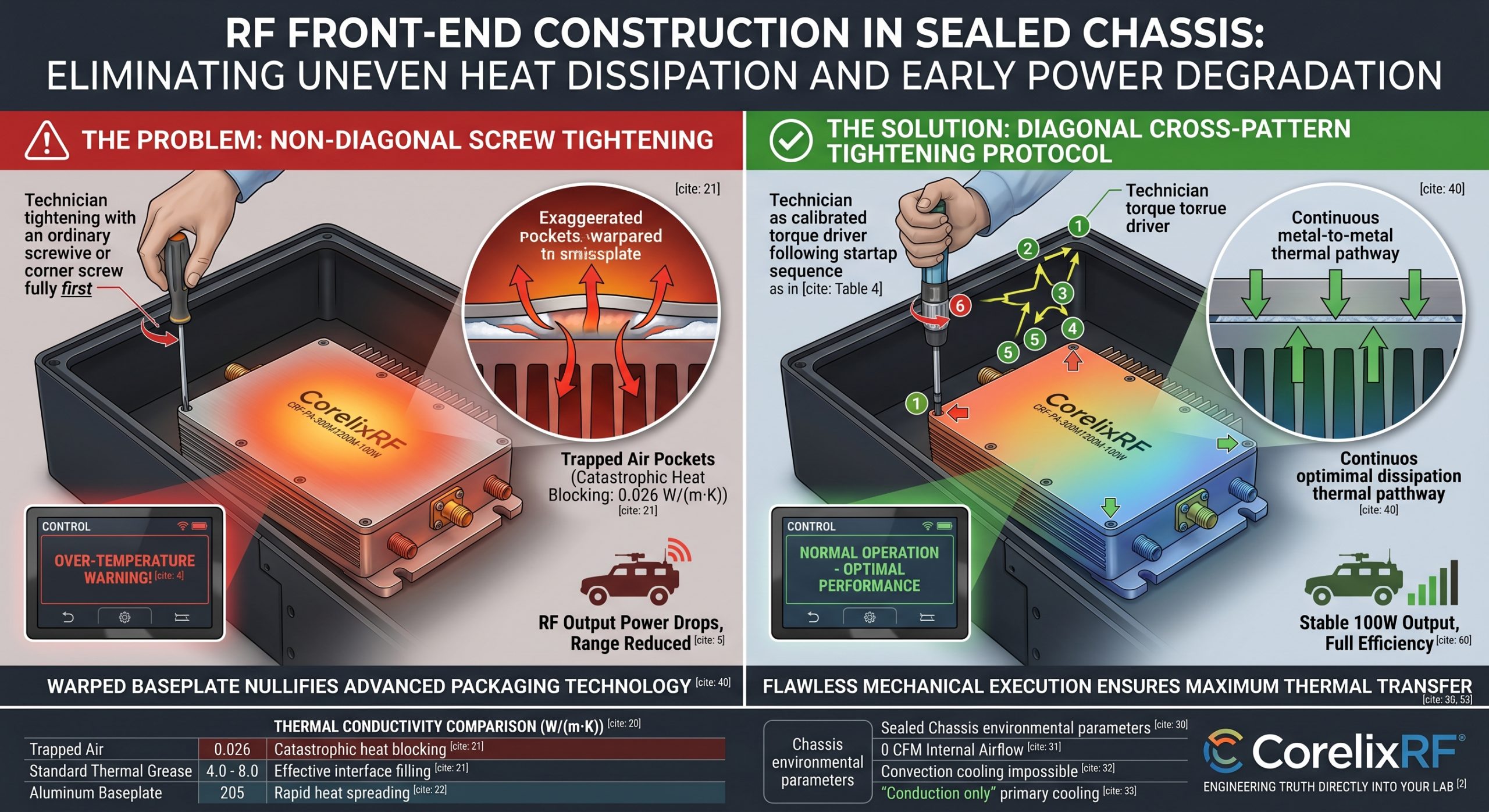
System integrators face catastrophic failures inside airless enclosures. Poor mechanical assembly destroys thermal pathways. CorelixRF brings 30 years of manufacturing truth directly into your engineering lab. We eliminate early power degradation through rigid hardware design. Proper RF Front-End Construction in Sealed Chassis demands absolute precision.
Use RF front-end thermal findings to shortlist rugged hardware
Baseplate cooling, heat flow, amplifier derating and enclosure layout should be reviewed together. CorelixRF can align RF front-end construction with amplifier, antenna and FAT requirements.
1. What Triggered Your System Thermal Alarm?
Military vehicles operate under heavy jamming loads. Command screens suddenly flash over-temperature warnings. RF output power drops significantly. Operators lose communication range instantly. Here is the deal. Technicians often rush baseplate installations during assembly. Rushing causes microscopic mechanical failures. RF Front-End Construction in Sealed Chassis requires zero margin for error. A technician tightened one corner screw completely before moving across. That single action warped your amplifier baseplate. Uneven mounting creates trapped air pockets. Air functions as an excellent thermal insulator. Heat cannot escape into your external heatsink. Transistor junction temperatures spike within minutes. Our engineering team sees this failure repeatedly during field troubleshooting. System throttling follows immediately. You cannot fix bad mechanics with software patches. Hardware selection logic dictates addressing physical interfaces first.
2. How Does Non-Diagonal Tightening Destroy Thermal Interfaces?
Mechanical torque follows strict physics principles. Fastening one corner completely lifts opposing edges. This microscopic tilt ruins surface coplanarity. You might be wondering. Why does a millimeter matter? Thermal grease requires uniform pressure across its entire surface area. Uneven pressure squeezes compound out from one side. The opposite side forms microscopic air gaps. Air exhibits a thermal conductivity of 0.026 W/(m·K). Standard thermal paste offers 4.0 W/(m·K). Trapped air fundamentally blocks heat transfer. RF Front-End Construction in Sealed Chassis fails completely here. Your 100-watt amplifier acts like a space heater inside an insulated box. Heat flows back into internal components. Solder joints experience massive thermal cycling stress. We demand strict diagonal cross-pattern tightening protocols. Our factory operators use calibrated torque drivers exclusively.
Thermal Conductivity Comparison
| Material Type | Thermal Conductivity (W/(m·K)) | Impact on RF Amplifiers |
| Trapped Air | 0.026 | Catastrophic heat blocking |
| Standard Thermal Grease | 4.0 – 8.0 | Effective interface filling |
| Aluminum Baseplate | 205 | Rapid heat spreading |
| Indium Foil | 86 | Premium interface solution |
3. Why Does Sealed Architecture Amplify Heat Trapping?
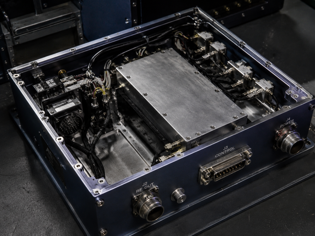
Airless enclosures lack convective cooling mechanisms. Fans cannot circulate fresh air internally. What is the real story? Conduction remains your singular path for heat rejection. Every component dumps thermal energy into a shared chassis structure. Ambient temperatures inside these boxes climb relentlessly. RF Front-End Construction in Sealed Chassis must manage this hostile environment. High-power amplifiers generate significant dissipated heat. If baseplate contact lacks uniformity, thermal resistance multiplies. Amplifier substrates become thermal bottlenecks. External heat sinks remain cold while internal silicon burns. We design modules specifically for extreme conduction cooling. Your upstream link budget calculations mean nothing if hardware melts. Engineering truth requires facing these thermodynamic realities. Passive cooling demands flawless mechanical execution.
Sealed Chassis Environmental Parameters
| Parameter | Typical Value | Engineering Consequence |
| Internal Airflow | 0 CFM | Convection cooling impossible |
| Ambient Rise Rate | +10°C per minute | Rapid thermal soaking |
| Primary Cooling Method | Conduction only | Baseplate contact critical |
| Humidity | Hermetically sealed | Zero moisture ingress |
4. What Are Physics Behind Early Power Degradation?
Gallium Nitride (GaN) transistors deliver massive power output. However their efficiency drops as junction temperatures rise. This is where it gets interesting… Electrons scatter more frequently within hot semiconductor lattices. Carrier mobility decreases rapidly. This phenomenon manifests as early power degradation. RF Front-End Construction in Sealed Chassis cannot tolerate efficiency drops. Rated 100W amplifiers might only output 70W when overheated. Gain flatness distorts completely. Your system integration fails its primary objective. Harmonics and spurious emissions worsen under thermal stress. Intermodulation distortion spikes. CorelixRF engineers focus heavily on extracting heat from GaN dies quickly. Warped baseplates nullify our advanced packaging technology. You must maintain continuous metal-to-metal thermal pathways.
5. How Do We Calculate Thermal Resistance For Amplifiers?
Thermodynamics dictates operating limits through resistance calculations. Total thermal resistance equals sum values of individual interface resistances. Equation formatting requires precision: RF Front-End Construction in Sealed Chassis demands minimizing this exact variable. A 0.1°C/W increase might seem small. Multiply that by 150W of dissipated power. Your transistor junction just gained 15°C unnecessarily. This single mathematical reality destroys MTBF calculations. We engineer flat surfaces. Installers must maintain that flatness.
6. Why CorelixRF Power Series Amplifiers Excel Structurally?
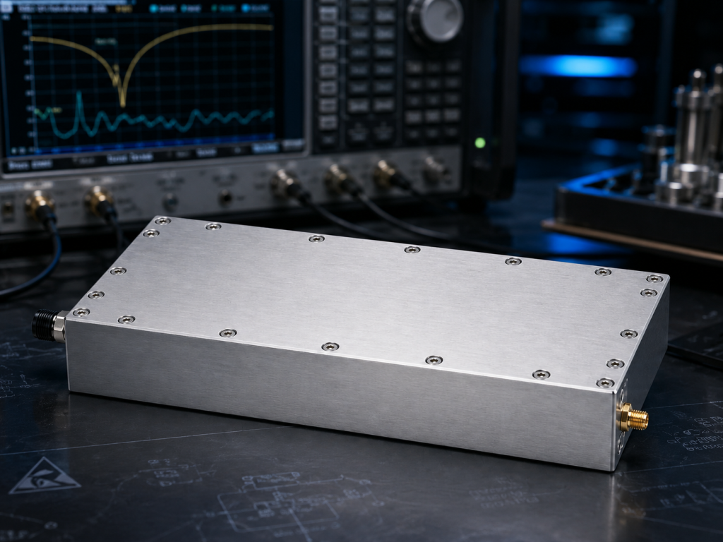
Our engineering heritage spans 30 years of RF manufacturing. We reject generic advertising claims. We build heavy-duty industrial hardware. Ready for the good part? Full Power Series units utilize premium CNC machined aluminum housings. Model CRF-PA-300M1200M-100W exemplifies this rugged design philosophy. Dimensions span strictly 200 × 158 × 25 mm. Weight remains under 1.4 kg. Massive bottom surface areas guarantee maximum thermal transfer. RF Front-End Construction in Sealed Chassis benefits massively from this footprint. We mill these baseplates flat within microns. Such precision prevents natural bowing under thermal expansion. Inputs utilize SMA-F connectors. Outputs feature N-F interfaces. Mechanical outline drawings leave zero ambiguity for system integrators.
Physical Specifications of CRF-PA-300M1200M-100W
| Parameter | Specification | Integration Benefit |
| Dimensions | 200 × 158 × 25 mm | Maximum surface area |
| Weight | ≤ 1.4 kg | Manageable payload |
| Cooling Method | External Heat Sink | Conduction optimized |
| Input Connector | SMA-F | Standard low-power interface |
| Output Connector | N-F | Robust high-power handling |
7. How Does CRF-PA-300M1200M-100W Handle Thermal Extremes?
Operating conditions inside closed enclosures push electronics toward destruction. Model CRF-PA-300M1200M-100W covers 300 – 1,200 MHz continuously. Rated output power reaches 100W. But here is the kicker. Producing 100W requires managing substantial DC power. Nominal supply voltage equals 28V. Operating current reaches 14A maximum. That equals nearly 400W of DC input. Dissipated heat surpasses 250W easily. RF Front-End Construction in Sealed Chassis must dissipate this thermal load. Operating temperatures span -40°C through +60°C. Storage limits extend from -55°C up toward +85°C. If installers ignore diagonal torquing that 250W has nowhere safe for escape.
8. What Baseplate Installation Protocols Ensure Stability?
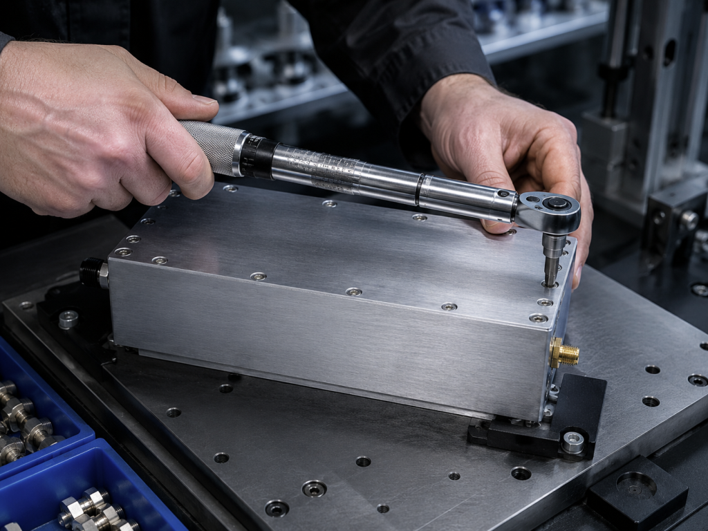
Integrators must adopt strict mechanical assembly guidelines. Begin by applying uniform 0.1mm layers of high-grade thermal compound. Place amplifiers carefully onto prepared heatsink surfaces. Truth be told. Finger-tighten all mounting screws first. Never use power tools during initial placement. Implement star-pattern or diagonal tightening sequences. Turn each fastener exactly one half-rotation sequentially. RF Front-End Construction in Sealed Chassis demands this methodical pacing. This technique compresses thermal grease evenly outward. It prevents trapped air pockets entirely. Final torque values must match fastener specifications precisely. Use calibrated torque wrenches without exception. Engineering truth relies on repeatable actions.
Recommended Diagonal Tightening Sequence
| Step | Action | Purpose |
| 1 | Finger-tighten all screws | Initial positioning |
| 2 | 50% Torque Top-Left | Begin compression |
| 3 | 50% Torque Bottom-Right | Balance baseplate |
| 4 | 50% Torque Top-Right | Expand pressure zone |
| 5 | 50% Torque Bottom-Left | Complete initial seal |
| 6 | 100% Torque across all | Finalize thermal bond |
9. How Do Firmware Alarms Prevent Catastrophic Failure?
Even perfect installations face unpredictable environmental spikes. CorelixRF integrates robust hardware protection mechanisms. D-Sub 15-Pin connectors provide comprehensive telemetry. Think about that. Pin 12 (TA) triggers alarms at 5V when temperatures exceed 80°C ±5°C. Amplifiers shut down automatically. Pin 13 (VA) protects against VSWR mismatches. Over-voltage protection triggers if supply exceeds 32V. Over-current alarms trigger beyond 16A. RF Front-End Construction in Sealed Chassis requires these failsafes. Pin 14 outputs analog voltage relative directly toward temperature at 10mV/°C. System controllers read this pin continuously. Integrators can throttle duty cycles before hardware shutdown occurs. RS485 serial communication handles real-time monitoring.
Critical Control Interface Pins
| Pin Number | Function | Trigger Condition |
| Pin 2 | Voltage Alarm | Exceeds 32V |
| Pin 3 | Current Alarm | Exceeds 16A |
| Pin 12 | Temperature Alarm (TA) | Exceeds 80°C ±5°C |
| Pin 13 | VSWR Alarm (VA) | Output port open/short |
| Pin 14 | Temperature Analog | 10mV/°C scaling |
10. What Represents Ultimate Hardware Selection Logic?
Building reliable communications requires viewing components systematically. Do not treat power amplifiers as black boxes. Understand their physical limitations thoroughly. Bottom line. Your BOM selection process must evaluate mechanical ruggedness alongside electrical specifications. RF Front-End Construction in Sealed Chassis exposes weak designs quickly. Choose vendors who understand laboratory realities. Our factory builds RF modules designed specifically for punishing abuse. Applications include UAV countermeasures, RF testing, and communication interference systems. We supply test data and pattern files directly. CE, FCC, ISO 9001, and GJB 9001C compliance frameworks back our quality. Stop replacing burned-out modules. Start installing them correctly initially.
Proper RF Front-End Construction in Sealed Chassis requires uncompromising mechanical discipline. Non-diagonal screw tightening destroys thermal pathways and causes rapid performance drops. CorelixRF designs ruggedized power amplifiers built specifically for conduction-cooled enclosures. Implement strict torque procedures alongside our advanced thermal protection circuitry. Contact our engineering team immediately for integration support and custom frequency configurations.
Q1: What triggers a system thermal alarm inside closed chassis environments?
Non-diagonal baseplate tightening warps metal surfaces, creating air gaps that block heat transfer and cause rapid transistor overheating.
Q2: How does non-diagonal tightening destroy thermal interfaces?
Torquing one corner fully lifts opposing edges, squeezing out thermal grease unevenly and replacing it with highly insulating trapped air pockets.
Q3: Why do sealed chassis architectures amplify heat trapping?
Airless enclosures lack convective airflow, forcing all internal components to rely entirely on conduction through baseplates into external heat sinks.
Q4: What are the physics behind early power degradation?
As Gallium Nitride (GaN) transistor junction temperatures rise due to poor cooling, electron mobility drops, causing efficiency and output power to plummet.
Q5: How do CorelixRF firmware alarms prevent catastrophic hardware failure? Our integrated telemetry monitors temperature continuously, shutting down the amplifier automatically when internal heat exceeds 80°C ±5°C.
Turn baseplate cooling into a measurable RFQ item
Baseplate cooling should be specified with mounting surface, flatness, thermal interface material, ambient range, airflow, duty cycle, output power and allowed gain drift. This gives engineering enough detail to judge whether a standard or modified amplifier platform fits.
Recommended next step: send the operating band, target output power, duty cycle, thermal or load condition, control interface, protection behavior and required FAT documents. CorelixRF can review this baseplate cooling for RF front-end construction requirement against standard amplifier platforms, RF front-end options and custom engineering constraints.