
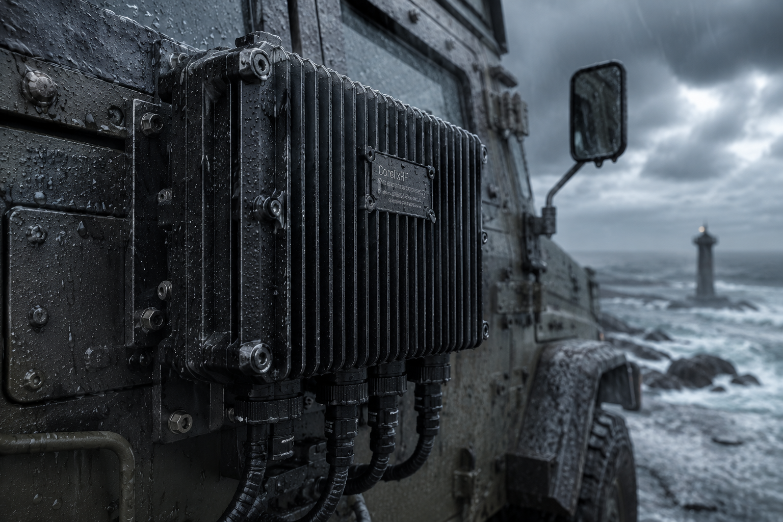
System alarms blare when thermal management fails inside tightly restricted environments. Engineers dread sudden power drops caused by improper mechanical assembly techniques. We provide robust architectural strategies solving these precise mechanical failures. Our two decades of RF experience guarantees practical fixes for high-power sealed enclosures.
What Causes Thermal Runaway in High-Power Sealed Enclosures?
Here is the deal: Mechanical assembly directly dictates electronic survival rates. When technicians ignore diagonal fastening sequences, microscopic air gaps form beneath amplifier baseplates. High-power sealed enclosures trap generated thermal energy rapidly. This trapped heat accelerates component degradation beyond acceptable limits. For instance, marine radar systems often exhibit sudden gain drops after deployment. Technicians usually blame faulty silicon instead of checking torque patterns. Another case involves airborne telemetry units shutting down mid-flight. Root causes trace back directly toward warped mounting surfaces. A third example features industrial microwave heating systems failing prematurely. Improper screw tightening warped those conductive plates severely. Baseplate warpage disrupts conductive pathways severely. Standard thermal paste cannot bridge gaps exceeding fifty microns effectively. High-power sealed enclosures demand absolute mechanical precision during final assembly stages. Without adequate venting, internal temperatures rise exponentially within minutes. We routinely observe GaN junction temperatures exceeding maximum ratings due solely toward poor screw torqueing. What is the real story? Warped plates create localized hotspots that standard sensors might miss initially. RF power modules like our CRF-PA-600M6000M-60W require optimal contact areas. System architects must specify precise torque values on all manufacturing drawings. Implementing strict quality control prevents catastrophic field failures completely. These environments present zero margin for mechanical errors. Proper heat sinking dictates long-term stability across all high-frequency transmission equipment. Every misplaced screw compromises carefully calculated thermal budgets significantly. We demand strict adherence regarding documented fastening procedures constantly.
Common Thermal Failures in High-Power Sealed Enclosures
| Failure Mode | Root Cause | Observable Symptom |
| Localized Hotspot | Uneven screw torque | Sudden output power drop |
| Baseplate Warpage | Non-diagonal tightening | Thermal paste pump-out |
| GaN Degradation | Trapped heat | Elevated noise floor |
How Does Non-Diagonal Torquing Alter the Thermal Interface?
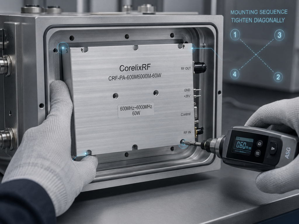
You might be wondering: why does a simple screw sequence matter? Fastening one side completely before addressing opposite corners lifts adjacent edges. This mechanical lever effect bends stiff aluminum or copper plates permanently. High-power sealed enclosures amplify this tiny structural deformation into massive thermal bottlenecks. Consider a stationary jammer deployed inside heavily corrosive salt fog environments. Enclosed chassis configurations prevent external airflow from assisting internal cooling plates. Operators noticed severe RF output reduction during continuous operation modes. Inspection revealed a completely dry thermal pad underneath one amplifier corner. Another case showed phased array panels warping after initial torqueing procedures. Technicians had fastened bolts linearly along single edges. A third scenario involved compact drone jammers experiencing rapid thermal shutdowns. Chassis metals absorbed intense solar radiation while internal heat remained trapped. This is where it gets interesting Microscopic deformations reduce actual contact area by over forty percent. Resulting thermal resistance spikes force active devices into overdrive immediately. Our engineering teams have analyzed countless returned units showing identical wear patterns. High-power sealed enclosures require perfectly flat mating surfaces targeting survival. We specify tight flatness tolerances across all CorelixRF product lines. System integrators must train assembly personnel regarding proper diagonal tightening techniques. Bowed metal surfaces trap microscopic air pockets acting as perfect thermal insulators. Thermal conductivity plummets drastically across these small unintentional voids. Engineers must combat these invisible gaps utilizing proper mechanical techniques.
Why Do RF Amplifiers Fail in Sealed Environments?
Let us dig deeper: Sealed environments lack convective cooling completely. Every watt of dissipated power must conduct through metal chassis walls. High-power sealed enclosures face immense challenges during continuous high-duty-cycle operations. If baseplates maintain poor contact, thermal energy reflects back into active transistors. We saw this specifically with vehicular anti-drone systems facing intense vibration. Constant mechanical shock combined with uneven initial torque caused screws backing out. VNA curves showed severe high-frequency roll-off during stress testing. Another field failure occurred inside sealed aerospace communications pods. Rapid altitude changes caused pressure differentials stressing warped baseplates further. Resulting thermal runaway destroyed expensive Gallium Nitride devices instantly. A third case involved underground mining communication nodes packed tightly inside waterproof boxes. Dust and moisture sealing trapped all generated heat internally. Ready for the good part? Proper architectural design accounts for these exact environmental stressors beforehand. We utilize advanced materials ensuring maximum thermal transfer rates constantly. High-power sealed enclosures need thick, rigid mounting platforms resisting deformation completely. Using multiple fastener points distributes mechanical loads evenly across entire surface areas. CorelixRF designs incorporate reinforced baseplates preventing warping under normal installation procedures. Proper engineering eliminates these entirely preventable mechanical failures. Vibration exacerbates any initial unevenness by slowly backing out under-torqued fasteners. Chassis resonance frequencies often align disastrously with loose mounting hardware. Securing RF modules permanently requires thread-locking compounds alongside correct torque application.
Environmental Stressors on RF Modules
| Environment | Primary Stressor | Effect on Baseplate |
| Vehicular | High-frequency vibration | Screw loosening |
| Aerospace | Pressure differentials | Mechanical fatigue |
| Mining | Sealed moisture barriers | Zero convective cooling |
What Are the Cascade Effects of Uneven Heat Dissipation?
But here is the kicker Heat does not just destroy components; it degrades signal integrity. Uneven thermal distribution shifts operating points across cascaded amplifier stages unpredictably. High-power sealed enclosures suffer from phase distortion when temperatures fluctuate rapidly. We observed early optical decay phenomena mimicking semiconductor aging perfectly. However, this degradation stemmed purely from localized thermal stress over time. For example, a wideband surveillance receiver exhibited strange intermodulation products during field trials. Uneven heating across parallel RF transistor blocks caused those specific anomalies. Another instance involved high-power test equipment inside sealed laboratory racks. Output power drifted significantly over a few hours of continuous operation. Thermal imaging revealed extreme temperature gradients across specific amplifier baseplates. A third situation occurred with fixed-site interference generators operating continuously. Noise floors elevated by several decibels due strictly toward inadequate thermal sinking. What is the real story? GaN technology handles high temperatures well but hates severe gradients. High-power sealed enclosures must maintain uniform temperatures preventing uneven device expansion. Our internal design practices ensure balanced thermal pathways across all critical components. We mitigate these cascade effects through meticulous hardware architecture choices. System designers should never underestimate mechanical assembly impacts upon RF performance. Semiconductor junctions expand and contract physically during high-power pulsing modes. Uneven baseplates restrict this natural thermal cycling, inducing micro-cracks inside GaN dies. Long-term reliability plummets when mechanical stress combines with extreme heat.
How Can System Architects Mitigate Mechanical Stress?
You might be wondering: what architectural choices prevent these catastrophic failures? First, specify heavy-duty baseplates resisting bending moments during installation procedures. High-power sealed enclosures benefit immensely from integrated thermal spreaders distributing heat laterally. Using phase-change thermal interface materials accommodates microscopic surface irregularities efficiently. One successful deployment involved military manpack radios utilizing grooved chassis designs. These grooves added structural rigidity while increasing total surface cooling area. Another successful architecture utilized precisely machined standoff pillars inside communication modules. These pillars guaranteed exact compression rates supporting internal thermal pads. A third excellent design featured blind tapped holes preventing chassis penetration entirely. This approach maintained strict environmental sealing while providing robust anchoring points. This is where it gets interesting Thick baseplates add weight but guarantee long-term RF reliability inherently. High-power sealed enclosures require balancing payload restrictions against thermal management necessities. We strongly recommend torque-limiting screwdrivers supporting all final production assembly lines. Documenting specific fastening sequences within standard operating procedures eliminates human errors. Robust architecture anticipates clumsy installation practices and compensates through mechanical over-engineering. Our CorelixRF modules incorporate these exact ruggedized principles. Engineers evaluating chassis concepts must simulate worst-case thermal scenarios thoroughly. Finite element analysis software reveals potential warping issues before manufacturing begins. Hardware prototyping validates these digital models preventing costly field failures.
Table 3: Mitigation Strategies for Mechanical Stress
| Strategy | Implementation | Benefit |
| Rigid Baseplates | Use 5mm+ thick copper | Resists warpage |
| Torque Control | Pre-set assembly tools | Ensures uniform pressure |
| Phase-change TIM | Apply specialized pads | Fills microscopic gaps |
What Role Does the CRF-PA-600M6000M-60W Play?
Here is the deal: True engineering requires matching specific hardware toward harsh operational realities. CorelixRF CRF-PA-600M6000M-60W modules provide sixty watts across ultra-wide bandwidths reliably. High-power sealed enclosures demand exactly this type of ruggedized GaN technology. Operating continuously from 600 through 6,000 MHz requires exceptional thermal management. We engineered this specific amplifier specifically targeting test, measurement, and interference applications. Consider a broadband jamming system deployed inside sealed vehicle compartments. This specific unit maintained full rated output power despite intense ambient heat. Another case involved aviation control monitoring systems packed densely into small racks. Standard 3U package dimensions allowed seamless mechanical integration immediately. A third application featured remote communication nodes handling continuous high-speed data streams. Our amplifier delivered consistent 51 dB gain without thermal throttling issues. Ready for the good part? Advanced GaN technology provides superior efficiency, reducing total dissipated heat significantly. High-power sealed enclosures require components generating minimal waste energy naturally. We designed built-in protection against over-voltage and over-temperature conditions directly. This architectural choice protects expensive internal circuitry from unpredictable external environments. This sixty-watt capability enables long-range transmission despite heavy structural shielding. Systems operating near 6,000 MHz require pristine signal clarity continuously. Our ruggedized design preserves spectral purity despite harsh external ambient temperatures.
How Does CorelixRF Address High VSWR in Harsh Contexts?
But here is the kicker Antenna damage frequently causes massive power reflections back into amplifiers. Sealed chassis systems rarely offer operators immediate physical access supporting troubleshooting. High-power sealed enclosures therefore require autonomous hardware-level protection mechanisms constantly. Our CRF-PA-600M6000M-60W handles an input VSWR up to 2:1 safely. Furthermore, built-in VSWR protection prevents catastrophic transistor failure during antenna faults. We analyzed a naval communication system suffering frequent antenna corrosion issues. CorelixRF modules survived repeated high-reflection events without performance degradation. Another scenario involved tactical vehicles breaking antennas off against low-hanging branches. Amplifiers recognized impedance mismatches and engaged protective circuits instantly. A third case featured test technicians accidentally disconnecting cables during high-power transmission. Internal over-drive protection saved entire RF chains from destruction. What is the real story? Reflected power generates extreme localized heating at specific transistor drain junctions. High-power sealed enclosures exacerbate this issue by trapping that sudden thermal spike. Our engineering team prioritized autonomous protection circuits inside every product. Reliable RF architecture demands planning regarding worst-case operational scenarios always. Reflected energy traveling backwards through RF chains creates destructive standing waves. These standing waves generate voltage spikes exceeding standard transistor breakdown ratings. Over-voltage protection acts alongside VSWR monitoring, creating an impenetrable defense layer.
Table 4: CRF-PA-600M6000M-60W Key Specifications
| Parameter | Specification | Note |
| Frequency Range | 600 – 6,000 MHz | Ultra-wideband coverage |
| Rated Output | 60 W | CW operation |
| Input VSWR | 2 : 1 | High tolerance |
| Gain | 51 dB | High amplification factor |
What Are the Thermal Dissipation Strategies for the Series?
You might be wondering: how do we manage sixty watts effectively? CRF-PA-600M6000M-60W units utilize forced air cooling within standard configurations. However, integrating this module inside high-power sealed enclosures requires system-level thinking. Engineers must couple amplifier baseplates directly onto external heat exchangers. We saw exceptional results when integrators used liquid-cooled cold plates alongside our units. One specific radar manufacturer reduced operating temperatures by twenty degrees Celsius. Another client utilized massive finned aluminum extrusions acting as external chassis bodies. They bolted our 3U package directly against that thick external wall. A third successful thermal strategy involved specialized heat pipes routing energy away. These pipes transferred thermal loads from internal amplifiers toward remote radiator fins. This is where it gets interesting… Modules operate safely between 0 and 50 degrees Celsius. High-power sealed enclosures must guarantee internal ambients never exceed these specified limits. We optimized internal component layouts minimizing localized thermal density across PCBs. Proper thermal architecture ensures long-term stability and consistent spectral purity. Air cooling requires carefully designed intake and exhaust venting pathways. Sealed systems often utilize internal fans circulating air against external cold plates. Maximizing internal convective currents distributes thermal loads across larger exterior surfaces.
Why Is Interface Control Critical for Remote Sealed Systems?
Let us dig deeper: Operators cannot physically interact with hardware sealed securely inside rugged boxes. Monitoring internal health parameters becomes absolutely mandatory supporting mission success. High-power sealed enclosures demand robust, reliable communication interfaces handling telemetry data. CRF-PA-600M6000M-60W amplifiers feature standard RS485 control interfaces specifically targeting this purpose. Remote systems depend entirely upon continuous digital feedback preventing sudden hardware failures. For example, an automated spectrum monitoring station required constant power level verifications. RS485 links provided real-time diagnostic data directly toward central command servers. Another deployment involved unmanned aerial vehicles utilizing custom payload enclosures. Telemetry channels monitored amplifier temperatures, allowing software-based duty cycle adjustments dynamically. A third instance saw border security jamming nodes controlled entirely via remote networks. Operators could monitor forward and reverse power statuses without opening sealed cabinets. Ready for the good part? We offer optional customization supporting GPIB or LAN remote control interfaces. High-power sealed enclosures integrate seamlessly into complex networked environments using these options. Proactive monitoring identifies thermal degradation trends before total system failure occurs. True engineering visibility extends far beyond physical chassis walls. Digital telemetry allows predictive maintenance scheduling based on actual operating conditions. Networked controllers can reduce amplifier drive levels automatically during extreme heatwaves. This closed-loop feedback mechanism prevents irreversible hardware damage during anomalies.
Table 5: Control and Monitoring Interfaces
| Interface Type | Standard/Optional | Application Context |
| RS485 | Standard | Industrial control networks |
| LAN | Optional Customization | IP-based remote monitoring |
| GPIB | Optional Customization | Automated test equipment |
How to Implement Proper Mechanical Assembly for RF Modules?
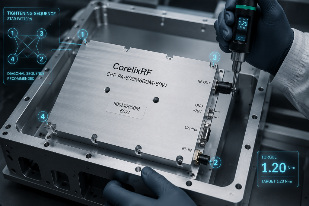
Here is the deal: Superior RF hardware fails quickly if poorly installed. Implementing rigorous mechanical assembly procedures guarantees long-lasting performance outdoors. High-power sealed enclosures require specific, documented torque sequences during final integration phases. Engineers must specify star-pattern tightening methods on all production assembly documents. First, technicians should finger-tighten all fasteners loosely aligning bare mounting plates. We recommend applying specialized thermal compounds uniformly using precision stencils only. One avionics manufacturer eliminated thermal failures completely after mandating stencil-based paste application. Another successful integrator instituted photographic documentation capturing every applied torque sequence. A third company utilized automated robotic screwdrivers guaranteeing absolute mechanical consistency across batches. What is the real story? Human error during assembly destroys more amplifiers than electrical overstress events. High-power sealed enclosures hide these manufacturing mistakes until catastrophic field failures happen. CorelixRF provides mechanical outline drawings ensuring clear integration references beforehand. Following basic engineering truths regarding mechanical fastening saves enormous replacement costs later. Always respect physical boundaries when dealing with high-power RF dissipation requirements. Quality assurance departments must verify torque tool calibration schedules strictly. Uncalibrated screwdrivers apply inconsistent pressure, ruining perfectly flat amplifier baseplates instantly. Investing time mastering basic mechanical assembly yields massive reliability dividends.
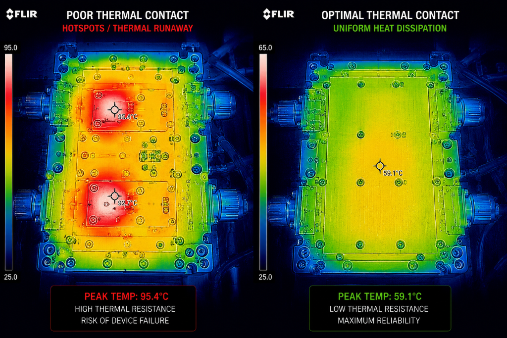
Mechanical precision dictates electronic survival within high-power sealed enclosures directly. Uneven baseplate torque causes severe thermal gradients, accelerating catastrophic component degradation rapidly. System architects must prioritize rigorous assembly protocols alongside robust RF module selection. Contact CorelixRF immediately evaluating our GaN-based CRF-PA-600M6000M-60W addressing your demanding applications.
Q1: What causes thermal runaway inside sealed chassis systems?
Uneven baseplate torquing creates microscopic air gaps blocking conductive heat transfer, causing rapid localized heating.
Q2: How does CorelixRF hardware protect against antenna mismatch?
Built-in VSWR protection circuitry handles reflections safely during continuous operation.
Q3: Why do we recommend star-pattern screw tightening?
This mechanical sequence prevents baseplate warpage, ensuring maximum surface contact targeting optimal thermal dissipation.
Q4: Which control interfaces exist on these RF modules?
RS485 comes standard, while LAN and GPIB remain available as optional customizations.
Q5: Can GaN technology improve sealed enclosure reliability?
Yes, GaN provides higher electrical efficiency, reducing total waste heat generated inside restricted environmental spaces.
Convert thermal risk into measurable RFQ requirements
Thermal reliability should be specified with output power, duty cycle, ambient range, airflow or baseplate path, soak time, allowed gain drift and alarm behavior. These details help CorelixRF match the request to a standard or modified amplifier platform.
Recommended next step: send the operating band, output power target, duty cycle, load condition, control interface, protection or thermal limits and required FAT documents. CorelixRF can review this How to Prevent Thermal Runaway in High-Power Sealed Enclosures? requirement against standard RF amplifier platforms, RF front-end options and controlled customization paths.