
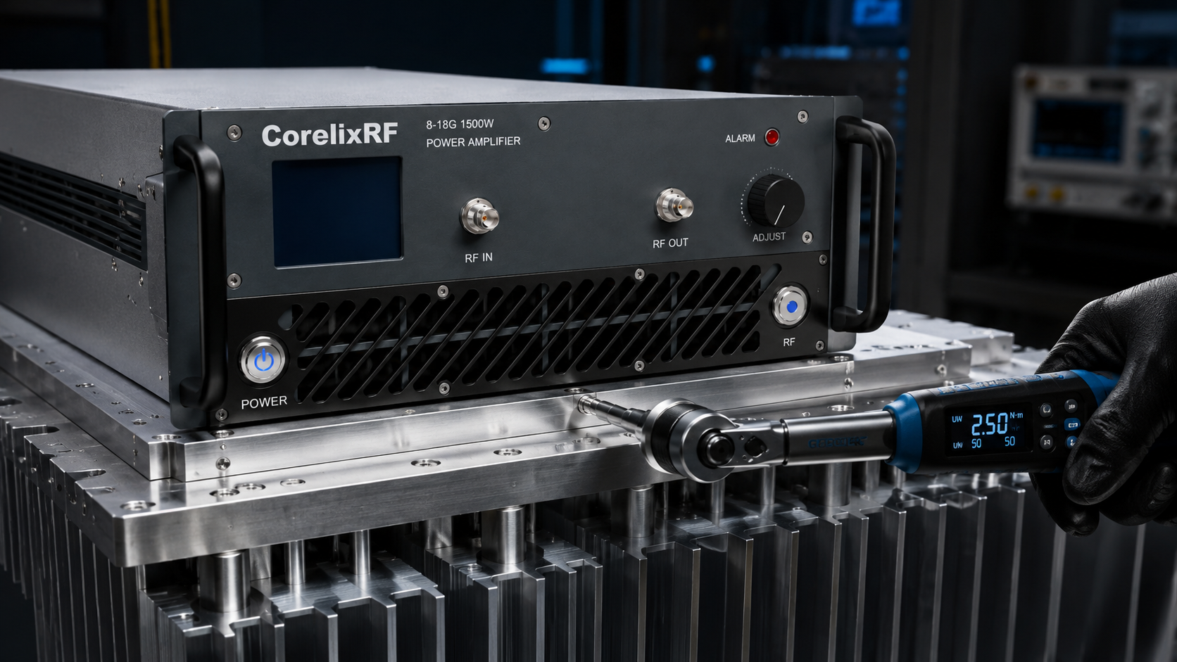
Troubleshooting Signal Anomalies in Sealed Enclosures: The Overlooked Uneven Heat Dissipation and Early Degradation Caused by Failing to Tighten Baseplate Screws Diagonally. You face sudden power slumps during high-duty-cycle radar testing inside unventilated pods. Your spectrum analyzer shows output power collapsing unexpectedly across several gigahertz bands. Operators frequently blame faulty amplifier modules outright without checking mechanical interfaces. Here is the deal, failing to torque baseplate mounting hardware using strict diagonal patterns creates microscopic air gaps that destroy thermal conductivity instantly. Such oversights cause localized hot spots, driving active transistor junction temperatures far beyond safe operating limits very rapidly. We routinely see expensive gallium nitride devices suffer early mortality simply because integration technicians fastened one side completely before addressing opposite corners. This article breaks down exactly why improper mechanical fastening ruins radio frequency performance and dictates mandatory field diagnostic procedures for isolating these exact thermal bottlenecks effectively. System integrators must adopt rigorous installation protocols, demanding calibrated tools for every single deployment.
Map sealed-enclosure heat risk to RF amplifier platform selection
Sealed RF enclosures need amplifier derating, baseplate review, airflow or conduction planning, protection logic and FAT evidence. CorelixRF can help translate those constraints into quote-ready hardware.
Identifying Symptoms of Poor Thermal Mating in Confined Spaces
System integrators working with tightly packed communication nodes often miss subtle indicators regarding severe thermal stress. When an amplifier operates inside a completely sealed chassis, natural convection simply does not exist. Heat must conduct perfectly through metal mating surfaces directly into external heat sinks. You might be wondering, what actually happens when technicians ignore proper torque sequences during installation? A poorly seated baseplate bends microscopically, establishing metal-to-metal contact on one edge while leaving tiny wedges of air on another side. Air acts as a fantastic insulator, causing thermal resistance beneath specific power transistors to skyrocket instantly. During continuous wave operation, these isolated hotspots force internal temperatures past critical thresholds before chassis-level sensors even register baseline increases. Your network analyzer will suddenly display significant gain compression and phase shifts because semiconductor mobility decreases rapidly at elevated temperatures. We measure these failures regularly during field deployments, noting affected modules exhibit permanent performance degradation long before triggering any system-level thermal alarms. Such hidden damage ultimately compromises entire mission profiles, demanding immediate mechanical audits.
Symptoms of Micro-Gap Thermal Failures
| Symptom Category | Observable Field Behavior | Underlying Physical Mechanism |
| RF Performance | Sudden gain drop during transmission | High channel temperatures reducing electron mobility |
| Reliability | Premature transistor failure | Prolonged operation beyond safe junction limits |
| Diagnostic | Normal chassis temperature readings | Heat failing to transfer across poor mating interfaces |
| Power Delivery | Noticeable output power slump | Thermal throttling affecting amplification efficiency |
The Physics Behind Diagonal Torquing and Heat Transfer
Mechanical stresses applied unevenly across flat aluminum heat spreaders guarantee microscopic warpage. Securing heavy high-power radio frequency amplifiers requires immense pressure distributed evenly across their entire footprint. What is the real story? Driving a screw down fully on top left corners forces bottom right corners upward slightly, warping internal baseplates permanently. Applying thermal compound cannot compensate for physical deformation exceeding several mils of thickness. High-power density devices require absolute planarity for thermal interface materials to function properly. When gaps exceed compound tolerances, localized thermal resistance creates massive bottlenecks for dissipated heat attempting an escape from active dies. We utilize advanced GaN technology requiring highly efficient thermal paths. Operating solid-state devices in restrictive environments demands flawless mechanical execution because trapped heat destroys electron mobility and accelerates electromigration inside semiconductor structures. Field engineers must mandate calibrated torque drivers and enforce strict cross-pattern tightening procedures during every single installation phase. Ignoring these mechanical realities guarantees catastrophic hardware failures during critical operational windows.
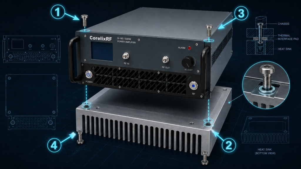
Torque Sequence Impact on Thermal Interface
| Fastening Method | Baseplate Warpage Risk | Thermal Transfer Efficiency | Field Reliability |
| Single-side tightening | Extremely High | Very Poor | High failure rate |
| Circular tightening | Moderate | Inconsistent | Unpredictable |
| Diagonal cross-pattern | Minimal | Optimal | Excellent |
| Uncalibrated torque | High | Variable | Prone to degradation |
Field Diagnostics Using Instrumentation
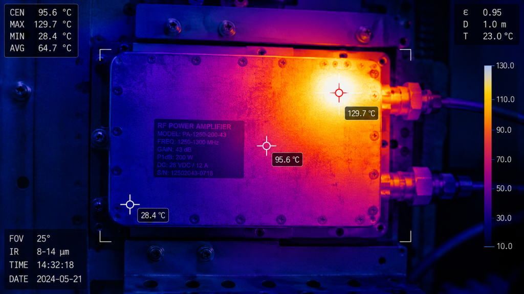
Troubleshooting suspected thermal anomalies requires specialized equipment alongside methodical testing procedures on site. You cannot rely on built-in chassis telemetry when evaluating microscopic mating failures beneath bolted assemblies. This is where it gets interesting, grabbing high-resolution thermal imaging cameras reveals exactly how heat propagates across mechanical boundaries during active transmission. We instruct technicians to apply continuous test signals and monitor external heat sinks directly opposite amplifier mounting locations. Properly seated modules produce uniform thermal blooms spreading evenly across cooling fins. Conversely, improperly torqued baseplates exhibit severe temperature gradients, showing intense localized heating directly behind tightly fastened screws alongside cold zones behind lifted corners. Simultaneously, monitoring forward power via directional couplers shows immediate correlations between rising internal die temperatures and collapsing output envelopes. If forward power drops while external sinks remain relatively cool, you have confirmed catastrophic interface failures requiring immediate re-installation. We demand comprehensive thermal audits prior to commissioning sealed electronic warfare pods.
Diagnostic Equipment and Expected Outcomes
| Equipment Used | Proper Installation Observation | Faulty Installation Observation |
| Thermal Imager | Uniform heat spread on sink | Intense localized hot spots |
| Spectrum Analyzer | Stable output power over time | Power slumping after minutes |
| Directional Coupler | Consistent forward power | Gradual decrease in forward power |
| Calibrated Torque Wrench | Uniform resistance on screws | Uneven or loose fasteners |
Applying the CorelixRF CRF-PA-8000M18000M-1500W
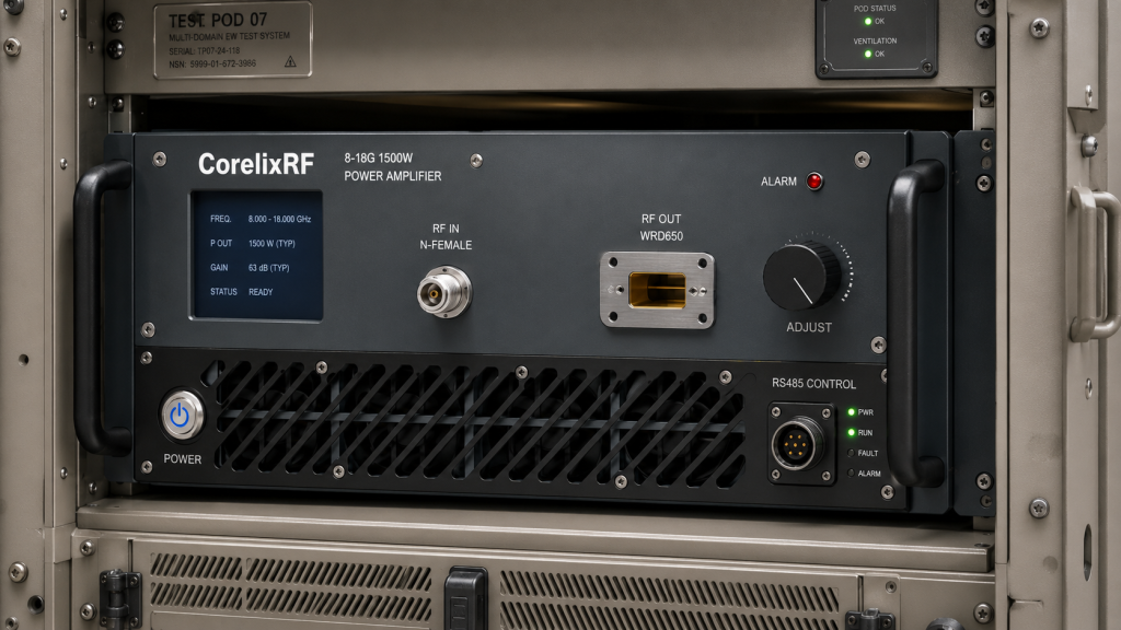
Replacing damaged components necessitates selecting hardware designed explicitly for abusive conditions and high-stress deployments. Integrators struggling with legacy tube amplifiers or fragile solid-state designs require robust modern alternatives. Ready for the good part? We developed the Wideband RF Power Amplifier CRF-PA-8000M18000M-1500W specifically for test, measurement, communication, interference, and aviation control applications. This unit delivers 1500 W of rated output power across massive 8,000 – 18,000 MHz frequency ranges. Our design incorporates advanced GaN technology, ensuring exceptional efficiency and ruggedness. It features built-in protection for over-voltage, over-temperature, over-drive and VSWR, safeguarding internal circuitry even when external systems fail. The amplifier provides typical gains of 62 dB with adjustable gain ranges of 20 dB, allowing precise calibration. Gain flatness remains between -6 dB and 6 dB. We mandate 50 Ω systems for all test conditions. By providing dedicated mechanical drawings for clear integration reference, we equip field teams with exact dimensions needed for flawless thermal mating. Connectors include Input N-Female and Output WRD650.
Key Specifications of CRF-PA-8000M18000M-1500W
| Parameter | Min | Typ | Max | Units | Source |
| Frequency Range | – | 8,000 – 18,000 | – | MHz | |
| Rated Output Power | 1500 | – | – | W | |
| Gain | 62 | – | – | dB | |
| Input VSWR | – | 1.5:1 | – | – |
System Integration and Protection Mechanisms
Deploying high-power RF systems inside unventilated enclosures demands redundant safety protocols alongside rigorous mechanical planning. You cannot simply bolt down massive amplifiers and expect prolonged survival without active monitoring. But here is the kicker, our equipment actively defends itself against integration errors through comprehensive internal telemetry and rapid shutdown capabilities. The CRF-PA-8000M18000M-1500W utilizes RS485 or LAN control interfaces, allowing system controllers continuous status polling. It operates reliably within temperatures spanning 0 to 50 °C. We designed hardware utilizing AC 380V±10%, 50/60Hz power supplies, accommodating standard industrial grids directly. The system utilizes air cooling, meaning your enclosure design must account for internal air circulation even if sealed externally. We offer optional forward/reverse power monitoring, over-input power protection, and GPIB communication interfaces for enhanced customization. Maintaining noise floors of -20 dBm/MHz ensures clean signal delivery without adding excessive interference. Spurious emissions remain at -60 dBc, while harmonics measure between -15 and -8 dBc. We strictly adhere to RoHS, CE / FCC, ISO 9001, and GJB 9001C compliance frameworks.
Integration Interfaces and Protections
| Feature Category | Specific Implementation | Value to Integrator | Source |
| Control Interface | RS485 / LAN | Remote telemetry and diagnostics | |
| Customization | GPIB, Power Monitoring | Adaptable to automated test setups | |
| Built-in Protection | VSWR, Over-temp, Over-drive | Prevents catastrophic hardware loss | |
| Operating Temp | 0 to 50 °C | Wide operational thermal envelope |
Improper mechanical fastening destroys sophisticated radio frequency systems rapidly through microscopic thermal isolation. Using calibrated torque tools and strict diagonal tightening patterns prevents localized hotspots and catastrophic transistor failures entirely. We recommend reviewing your integration protocols and upgrading to resilient hardware immediately. Contact CorelixRF engineers today for detailed system evaluations or request test data files applicable for your specific project review.
Q1: What is the consequence of failing to tighten screws diagonally?
Failing to follow cross-patterns warps baseplates, creating microscopic air gaps that block heat transfer and cause early device failure.
Q2: How does an improperly seated amplifier behave in the field?
You will observe sudden output power slumps and significant gain compression because trapped heat rapidly reduces semiconductor electron mobility.
Q3: How can I diagnose a thermal mating issue on site?
Use thermal imagers looking for intense localized heating behind tightly fastened screws alongside cold zones behind lifted corners.
Q4: What are the specifications of the recommended CorelixRF solution? The CRF-PA-8000M18000M-1500W delivers 1500 W across 8,000 – 18,000 MHz utilizing advanced GaN technology and extensive built-in protections.
Q5: What control interfaces are available for system integration? We provide RS485 and LAN interfaces standard, with optional GPIB communication available for customized automated test environments.
Turn heat dissipation concerns into an engineering review
For sealed or high-temperature installations, share enclosure volume, airflow, baseplate path, ambient range, duty cycle, output power and thermal alarm requirements so the amplifier can be reviewed against real operating conditions.
Recommended next step: send the operating band, required output power, duty cycle, load condition, control interface, cooling limit, protection behavior and required FAT documents. CorelixRF can map this sealed enclosure RF amplifier heat dissipation requirement to a standard platform, a controlled modification or a custom RF build.