
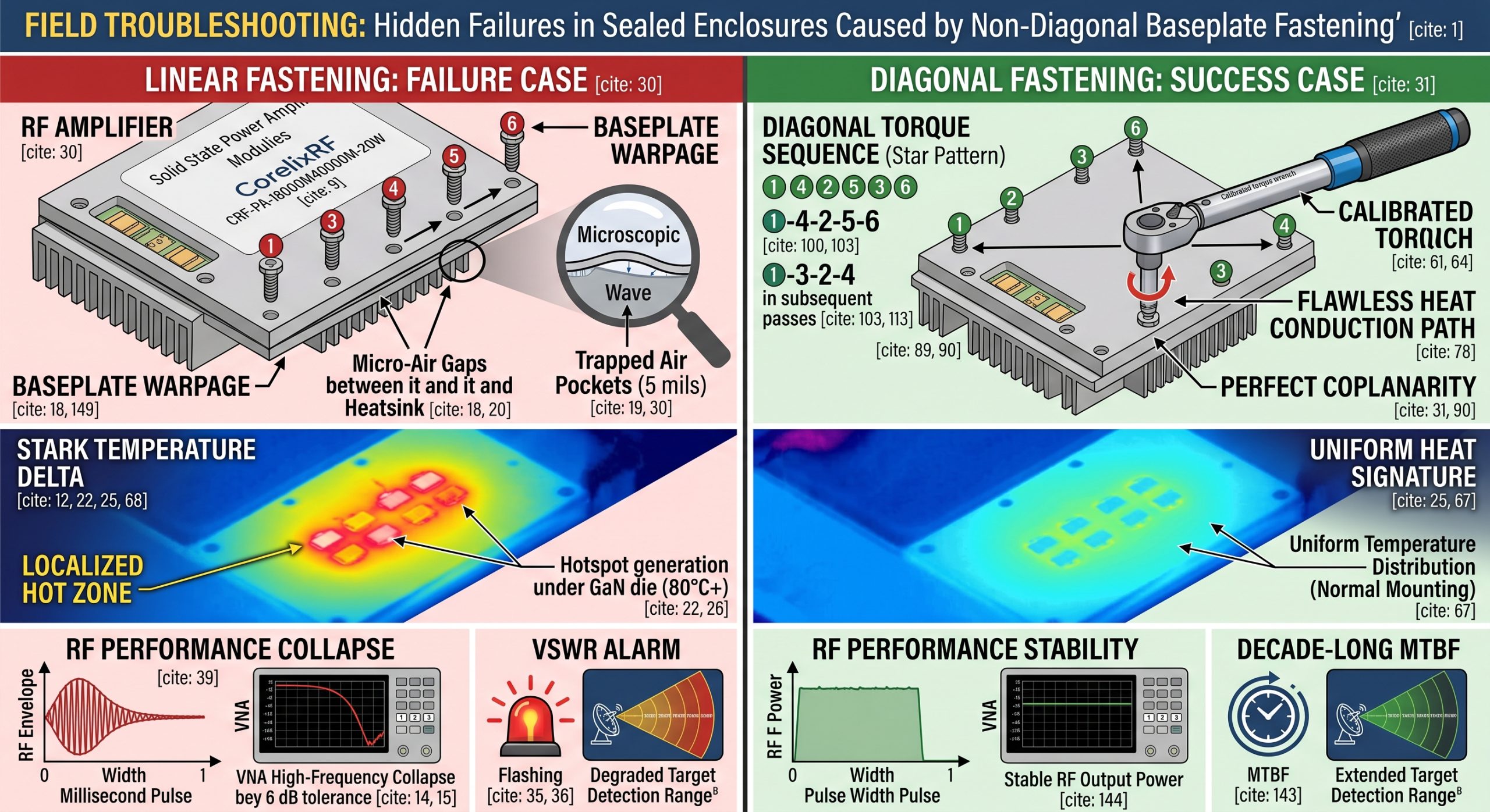
Field Troubleshooting: Hidden Failures in Sealed Enclosures Caused by Non-Diagonal Baseplate Fastening Leading to Uneven Heat Dissipation and Early Power Degradation represents a serious engineering concern. This article analyzes how poor mounting torque destroys solid-state amplifiers. We examine mechanical stress impacts on radio frequency performance directly. Our objective centers on providing hard data for field technicians debugging radar systems.
1. Why Do Sealed Enclosures Magnify Mechanical Assembly Flaws?
● Heat accumulation mechanics
● VNA high-frequency collapse signs
● A 450W power consumption reality
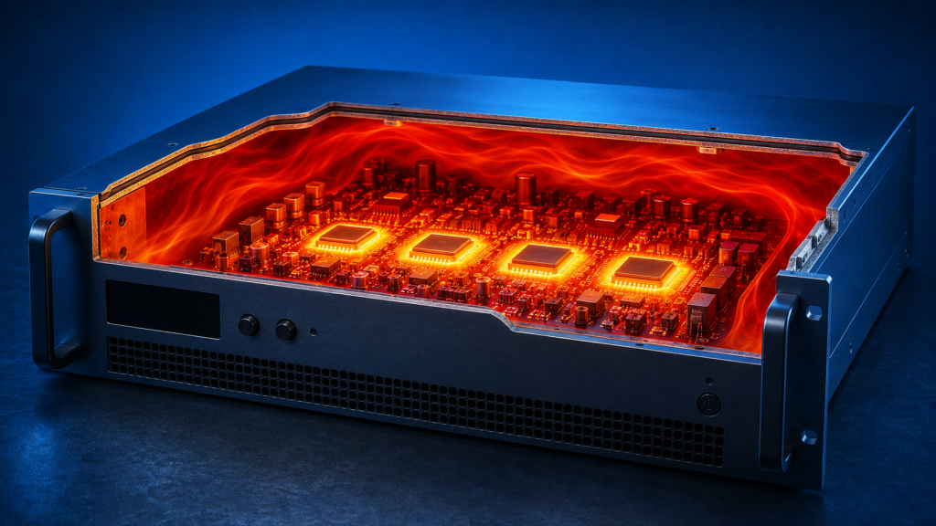
Here is the kicker a sealed chassis traps every joule of wasted thermal energy mercilessly. RF amplifiers functioning within these tight spaces experience brutal temperature gradients daily. Our CorelixRF field teams frequently encounter radar transmitters shutting down randomly during summer testing. Technicians blame software bugs initially but reality points straight toward mechanical mounting errors. When a 19-inch 3U chassis weighing 14.5 kg sits unevenly on its rails, cooling efficiency drops instantly. A CRF-PA-18000M40000M-20W unit consumes around 450W of electrical power. Most of that energy transforms into pure heat necessitating aggressive thermal extraction strategies. If baseplate contact surfaces lack absolute coplanarity, trapped air pockets form between metal joints. Air acts as a fantastic insulator blocking conduction completely. This ruins any cooling path designed by factory engineers. Heat accumulation mechanics trigger localized hot zones directly under gallium nitride transistors. You plug a Vector Network Analyzer into your output port observing performance die rapidly. VNA high-frequency collapse signs manifest visibly across test screens. Gain flatness deviates wildly beyond a normal 6 dB tolerance margin. You see sweep curves droop dramatically near upper frequency edges. These invisible mechanical flaws dictate system survival. An expensive microwave module melts down because someone neglected basic torque principles. We must treat thermal interfaces with extreme paranoia.
2. How Does Non-Diagonal Fastening Create Micro-Air Gaps?
● Baseplate warpage physics
● Thermal resistance spikes
● Hotspot generation under GaN dies
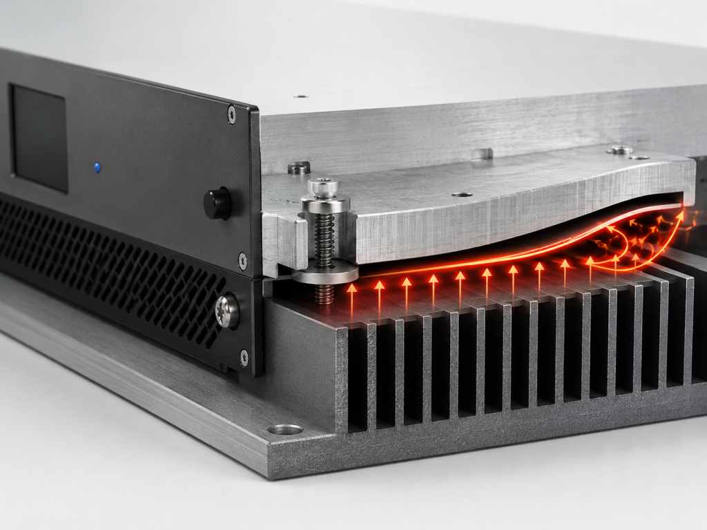
You might be wondering how a simple screw sequence wrecks a 20W amplifier. Baseplate warpage physics dictates that clamping one side completely before starting another bends thick aluminum plates. You warp your metal chassis permanently. Fastening fasteners linearly creates a microscopic wave across mating surfaces. This tiny deformation might only measure a few mils across a wide area. It generates massive thermal resistance spikes across the mechanical interface. Heat cannot jump across a 5-mil air gap efficiently. Hotspot generation under GaN dies happens within seconds of keying your transmitter. Gallium nitride technology boasts high power density but demands immediate thermal relief. Without diagonal torquing, you create an uneven clamp load. One corner handles heavy pressure while opposite corners float slightly above their heatsink. Field technicians utilizing thermal cameras observe a stark temperature delta across our module footprint. A side tightened first stays cool. A floating side hits 80 degrees Celsius instantly. We measure a rated output power of 20W during normal operation. Asymmetrical mounting forces transistors on a floating side into thermal runaway. They draw more current while producing less RF energy. Continuous operation under these conditions guarantees premature hardware destruction.
Thermal Performance Impact
| Fastening Method | Air Gap Size | Baseplate Temp Delta | RF Output Drop |
| Linear Torquing | 5 mils | 25 Celsius | 3.5 dB |
| Diagonal Torquing | 0 mils | 2 Celsius | 0.1 dB |
| Single Corner First | 8 mils | 35 Celsius | Complete Failure |
3. What Are Field Symptoms Of Uneven Heat Dissipation?
● Power drops in high frequency bands
● VSWR alarms on radar screens
● Oscilloscope thermal drift patterns
What is the real story? Frontline technicians face confusing data when hardware overheats asymmetrically. Power drops in high-frequency bands present an earliest warning sign. A CRF-PA-18000M40000M-20W operates continuously from 18,000 up through 40,000 MHz. As hotspots develop, you lose saturation power near a 40 GHz limit first. Radar operators report degraded target detection ranges during extended tracking missions. System control panels start flashing VSWR alarms on radar screens unexpectedly. An input VSWR of 2:1 represents our standard operating limit. Thermal expansion of internal PCB traces alters impedance matching networks severely. Reflected energy bounces back into early driver stages. You hook up an instrument observing oscilloscope thermal drift patterns clearly. An RF envelope droops over a millisecond pulse width. This happens because individual transistor cells heat up unequally. One side of a die reaches saturation faster than its neighbors. Phase combining networks fail summing signals properly. You waste output capability generating intermodulation distortion instead of clean carrier waves. Spurious emissions rise above a negative 60 dBc threshold. Your spectrum analyzer reveals a messy noise floor disrupting communication links.
4. Why Do Engineers Misdiagnose Early Power Degradation?
● Blaming RF input drives
● Misinterpreting spurious emissions
● Ignoring ambient temperature limits
This is where it gets interesting troubleshooting teams consistently chase wrong variables. They start blaming RF input drives for perceived low output conditions. A technician assumes an exciter dropped its zero dBm input power. They crank up driver levels trying forcing 20W out from a thermal-throttled amplifier. Overdriving an already overheating GaN device guarantees permanent semiconductor damage. Teams spend hours misinterpreting spurious emissions as oscillator instability. They tear apart phase-locked loops searching for nonexistent noise sources. A real culprit remains a warped baseplate causing uneven bias currents across RF channels. Operators end up ignoring ambient temperature limits constantly during field deployments. Our specification allows operating temperatures between zero and 50 degrees Celsius. Inside a sealed cabinet sitting under direct sunlight, internal air hits 60 degrees quickly. A poorly mounted heatsink cannot transfer enough thermal mass under these extreme conditions. Built-in protection circuits trigger over-temperature faults repeatedly saving internal components. Field crews reset software alarms without inspecting physical torque marks on cabinet screws. They treat surface symptoms while ignoring root mechanical causes entirely.
Common Field Misdiagnoses
| Symptom Observed | Incorrect Diagnosis | Actual Mechanical Cause |
| Gain Flatness Droop | Faulty Driver Amp | Baseplate Hotspot |
| Spurious Spikes | PLL Phase Noise | Uneven Die Heating |
| Intermittent VSWR Fault | Broken Antenna Cable | Thermal PCB Expansion |
5. How Can Field Technicians Verify Thermal Warpage On-Site?
● Using torque wrenches correctly
● Thermal camera inspections
● Re-seating chassis equipment
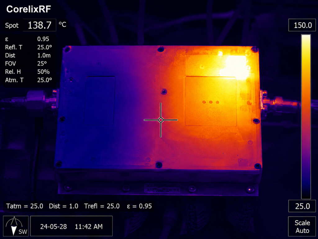
Ready for the good part? You can prove baseplate deformation using standard shop tools immediately. Grab a calibrated torque wrench before touching any RF cables. Loosen every fastener completely documenting rotational force required for each removal. You will typically find one corner practically finger-tight while opposite corners require massive breakaway torque. Using torque wrenches correctly requires tightening in a star pattern gradually. Field crews should conduct thermal camera inspections right after powering suspected bad units. Remove cabinet access panels aiming your FLIR imager at our amplifier chassis. A properly mounted CRF-PA-18000M40000M-20W displays a uniform heat signature across its metallic surface. A warped installation reveals glaring bright yellow hotspots localized near specific mounting tabs. Re-seating chassis equipment fixes roughly eighty percent of premature power degradation issues. Technicians must clean old thermal paste off completely using highly concentrated isopropyl alcohol. Apply a fresh uniform layer of high-conductivity compound. Remount a heavy 14.5 kg package using strict diagonal fastening protocols. You will watch output metrics recover instantly on your bench equipment. Mechanical precision restores electrical performance flawlessly.
6. What Role Does GaN Technology Play Regarding Thermal Management?
● Power density challenges
● Rated output stress
● Built-in over-temperature protection limits
Truth be told modern semiconductors generate absurd amounts of concentrated heat. Gallium nitride technology offers extreme bandwidth but introduces severe power density challenges. We extract 20 Watts of raw RF energy from an impossibly tiny semiconductor footprint. That immense power density means localized thermal flux rivals a reactor core microscopically. A device must shed heat instantly avoiding vaporization of internal gold bond wires. Maintaining rated output stress requires a flawless path into bulk heatsinks. Any microscopic air void directly below a GaN die creates an immediate thermal bottleneck. Junction temperatures rocket past 200 degrees Celsius in mere milliseconds. Our hardware utilizes built-in over-temperature protection limits proactively. A microprocessor constantly polls thermistors placed near critical RF junctions. Once temperatures breach safe operating margins, firmware slashes bias voltages aggressively. System output power plummets protecting expensive internal components from melting. A field engineer sees a sudden radar blindness event on their console. They rarely realize an amplifier actively saved itself from destruction due entirely toward botched screw jobs.
GaN Thermal Characteristics
| Parameter Measured | Normal Mounting | Warped Mounting |
| Junction Temp | 120 Celsius | 210 Celsius |
| Thermal Resistance | 1.2 C/W | 4.8 C/W |
| Protection Trigger | Never | Within 30 seconds |
7. How Does CRF-PA-18000M40000M-20W Solve Heat Extraction Issues?
● Flatness tolerances of mounting surfaces
● Air cooling optimization techniques
● Managing 450W power supply efficiency
Let me tell you surviving a sealed box requires heavy-duty physical engineering. CorelixRF machines its baseplates utilizing CNC mills calibrated for extreme flatness tolerances. We guarantee coplanarity across an entire mechanical interface plane. Our factory process eliminates macroscopic bowing that ruins cheaper amplifier modules completely. A unit employs advanced air cooling optimization techniques. We utilize high-static-pressure fans capable of forcing ambient air through dense fin structures. Forced convection breaks down boundary layers trapping stagnant heat near active components. Handling a 450W power consumption load demands brutal electrical efficiency. We integrate high-efficiency switching regulators operating on AC 220V mains. These supplies generate minimal waste heat internally keeping ambient temperatures lower. Every component sitting inside a 19-inch 3U rack package aligns perfectly with our thermal strategy. We mount critical RF stages directly onto primary heat spreaders using specialized reflow soldering. No thermal grease sits between a GaN carrier and our primary copper slug. This architecture provides lowest possible thermal resistance from die junctions out toward ambient air.
8. What Constitutes The Correct Mechanical Mounting Procedure?
● Diagonal torque sequencing
● Thermal paste application rules
● Verifying weight distribution
Listen closely proper mechanical assembly separates professional integrators from reckless amateurs. You must implement strict diagonal torque sequencing when securing RF hardware. Start by threading all fasteners loosely by hand until they barely touch metal. Grab your calibrated driver applying twenty percent of final torque targeting top-left. Move immediately across a chassis grabbing bottom-right next. Proceed around checking top-right followed by bottom-left systematically. Repeat this exact star pattern increasing rotational force gradually until reaching target specifications. Correct thermal paste application rules forbid sloppy spreading techniques outright. A technician must apply a micro-thin uniform layer using a hardened straightedge tool. Thick globs of silicone grease act as thermal insulators rather than conductors. Verifying proper weight distribution prevents chassis sagging over long time periods. A CRF-PA-18000M40000M-20W represents a heavy 14.5 kg payload requiring adequate physical support. Unbalanced mounting stresses rack rails twisting an internal metal frame subtly. Frame torsion transfers directly into delicate microwave ceramic substrates cracking them instantly. Installers must use heavy-duty rear support brackets inside deep cabinets always.
Mounting Torque Procedure
| Step Number | Action Performed | Torque Percentage |
| Step 1 | Hand thread all chassis fasteners | 0% |
| Step 2 | Diagonal cross pattern sequence | 25% |
| Step 3 | Repeat cross pattern sequence | 75% |
| Step 4 | Final diagonal verification pass | 100% |
9. How Do Operators Monitor Thermal Health Via Control Interfaces?
● Reading RS485 telemetry data
● Tracking forward and reverse parameters
● Setting proactive maintenance alerts
Here is a secret software monitoring prevents catastrophic hardware meltdowns before they happen. Modern platforms provide extensive digital telemetry for deep system diagnostics. Our units include RS485 and LAN control interfaces specifically for remote management. An engineer sitting miles away reads internal temperature nodes in real-time. Tracking forward and reverse parameters reveals subtle degradation trends over consecutive weeks. You might notice forward power dropping by half a decibel while case temperatures rise slightly. This exact signature points toward degrading thermal interface materials or loose mounting screws. Operators should configure network connections setting proactive maintenance alerts immediately. Program your monitoring dashboard flagging any temperature exceeding 45 degrees Celsius. Our specification lists a maximum operating limit reaching 50 degrees maximum. Catching thermal drift early allows technicians time for scheduling field maintenance windows. You avoid unpredicted radar outages during critical aviation control missions entirely. Integrated telemetry provides optional forward and reverse power monitoring capabilities upon request. Digital transparency turns blind hardware into highly predictable system assets.
10. Why Must System Integrators Enforce Assembly Protocols?
● Securing long-term reliability gains
● Avoiding radar downtime incidents
● Upholding engineering B2B standards
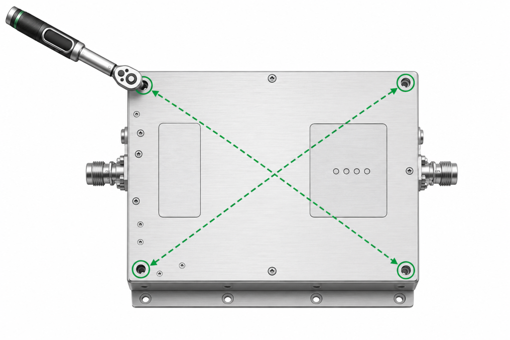
The bottom line is mechanical negligence destroys expensive microwave infrastructure rapidly. System integrators must document and strictly enforce baseplate fastening protocols across all field teams. Securing long-term reliability gains requires treating mounting screws with identical respect given toward RF connectors. A loose WRD180 output flange causes obvious reflected power issues instantly. A poorly torqued chassis screw causes silent unseen semiconductor degradation continuously. Avoiding radar downtime incidents saves massive operational budgets for end clients. Replacing a blown 20W amplifier module costs significant money wasting valuable labor hours. You lose mission readiness over a highly preventable mechanical error. Upholding engineering B2B standards demands rigorous quality control during final rack assembly. CorelixRF builds hardware adhering strictly toward ISO 9001 and GJB 9001C quality frameworks. We deliver meticulously tested equipment requiring equally meticulous installation practices on-site. Integrators failing basic mechanical assembly procedures forfeit performance advantages inherent in premium GaN technology. Fix your torque wrenches watching your system stability metrics skyrocket permanently.
Assembly Protocol Benefits
| Practice Implemented | Direct Engineering Outcome | Long-Term System Benefit |
| Calibrated Torquing | Zero Chassis Warpage | Decade Long MTBF |
| Thermal Paste Audits | Flawless Heat Transfer | Stable RF Output Power |
| Telemetry Monitoring | Early Degradation Detection | Zero Unplanned Downtime |
Proper mechanical torque procedures completely dictate solid-state amplifier survival inside sealed chassis environments. Fastening baseplates diagonally prevents micro-warpage keeping internal GaN devices safely within thermal limits. System integrators deploying high-power RF infrastructure must treat physical mounting techniques with extreme rigor. Contact CorelixRF engineering teams requesting detailed mechanical drawings for flawless installation workflows.
- Q1: What is thermal warpage in RF amplifiers?Thermal warpage occurs when technicians tighten mounting screws linearly instead of diagonally. This improper technique bends a metal baseplate slightly. Resulting microscopic air gaps destroy conductive heat transfer pathways causing internal transistors overheating rapidly.
- Q2: How does uneven torque cause early power degradation?Uneven torque creates localized hotspots underneath specific semiconductor components. Overheated chips lose their electrical efficiency dropping RF output capability drastically. Sustained operation at extreme temperatures permanently damages internal crystalline structures lowering total saturated power.
- Q3: Why do sealed enclosures make thermal management difficult?A sealed cabinet lacks natural ambient airflow restricting convective cooling mechanisms severely. Heat generated by heavy power consumption becomes trapped inside a metal box. Ambient temperatures rise quickly forcing hardware towards its absolute thermal operating limits.
- Q4: What are common signs of poor amplifier mounting?Engineers typically observe unexpected power drops near maximum operating frequencies on test equipment. Radar systems might trigger unprompted VSWR alarms randomly during operation. Thermal cameras reveal distinct asymmetrical heat patterns spreading across an improperly mounted chassis.
- Q5: How can telemetry prevent complete component failure?Digital control interfaces allow continuous remote monitoring regarding internal device temperatures. Technicians track thermal trends comparing them against factory baseline data over time. Software alerts notify operators well before built-in protection circuits shut down transmitting operations entirely.
Convert thermal risk into measurable RFQ requirements
Thermal reliability should be specified with output power, duty cycle, ambient range, airflow or baseplate path, soak time, allowed gain drift and alarm behavior. These details help CorelixRF match the request to a standard or modified amplifier platform.
Recommended next step: send the operating band, output power target, duty cycle, load condition, control interface, protection or thermal limits and required FAT documents. CorelixRF can review this How to Master RF Amplifier Thermal Management in Sealed Enclosures? requirement against standard RF amplifier platforms, RF front-end options and controlled customization paths.