
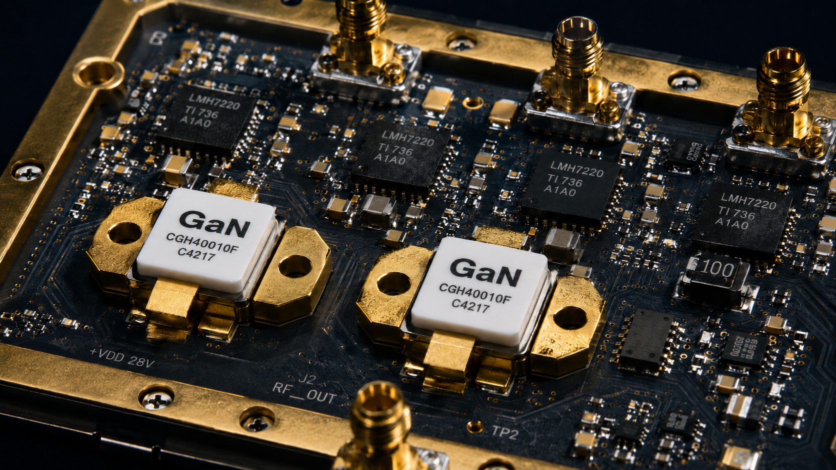
The Hard Reality
Troubleshooting C-UAS (Counter-Unmanned Aircraft Systems) VSWR alarms demands facing absolute engineering truth. During field deployments, system integrators frequently encounter catastrophic equipment failures: the moment transmission initiates, glaring red VSWR alarms trigger deep within the equipment rack, paralyzing the entire RF defense system. Complex physical environments ruthlessly destroy fragile signal links. True system survivability requires RF hardware architectures built upon harsh physical realities, not just perfect laboratory data.
1. Why Do C-UAS Vehicles Experience VSWR Alarms On-Site?
Field deployments expose sensitive microwave electronics to harsh environments that labs cannot simulate. Integrators typically mount amplifier modules in standard vehicle racks, with transmitting antennas towering on telescopic masts. This physical architecture necessitates long coaxial cable connections. The fundamental physical causes of these alarms include:
- Continuous Mechanical Stress: Violent chassis vibrations constantly wear down and loosen every physical connection point.
- Severe Thermal Expansion: Extreme temperature fluctuations alter the internal physical dimensions of inferior RF connectors.
- Severe Impedance Mismatch: Microscopic structural deformations destroy the nominal 50-ohm characteristic impedance. Forward RF energy hits an invisible electrical barrier, sending massive reflected power surging back into the main amplifier.
2. How Does RF Cable Insertion Loss Hide System-Level Disasters?
Long coaxial cables introduce significant signal attenuation (insertion loss) at high frequencies like 5.8GHz. Not only does this weaken the forward power reaching the antenna, but more fatally, the cable’s attenuation simultaneously “eats” the returning reflected energy.
When directional couplers measure return power at the amplifier output, the readings on the panel may appear safely low due to the long cable’s two-way attenuation. However, the actual condition at the antenna connection is highly destructive. Before software alarms can even trigger, reflected energy rapidly forms destructive voltage antinodes, physically obliterating fragile output transistors.
| Cable Attenuation Metrics | Frequency Band | Insertion Loss |
| Standard RG-58 | 5.8GHz | 1.5 dB/m |
| Premium LMR-400 | 5.8GHz | 0.3 dB/m |
| Mil-Spec LMR-600 | 5.8GHz | 0.2 dB/m |
3. The Fatal Role of Inferior Connectors in Impedance Mismatch
Mass-produced commercial N-type connectors often suffer from terrible mechanical tolerances. At microwave frequencies, these tiny physical deviations become massive electrical roadblocks: center pins deviate slightly from mathematical centerlines, or outer conductor mating surfaces lack perfect concentricity.
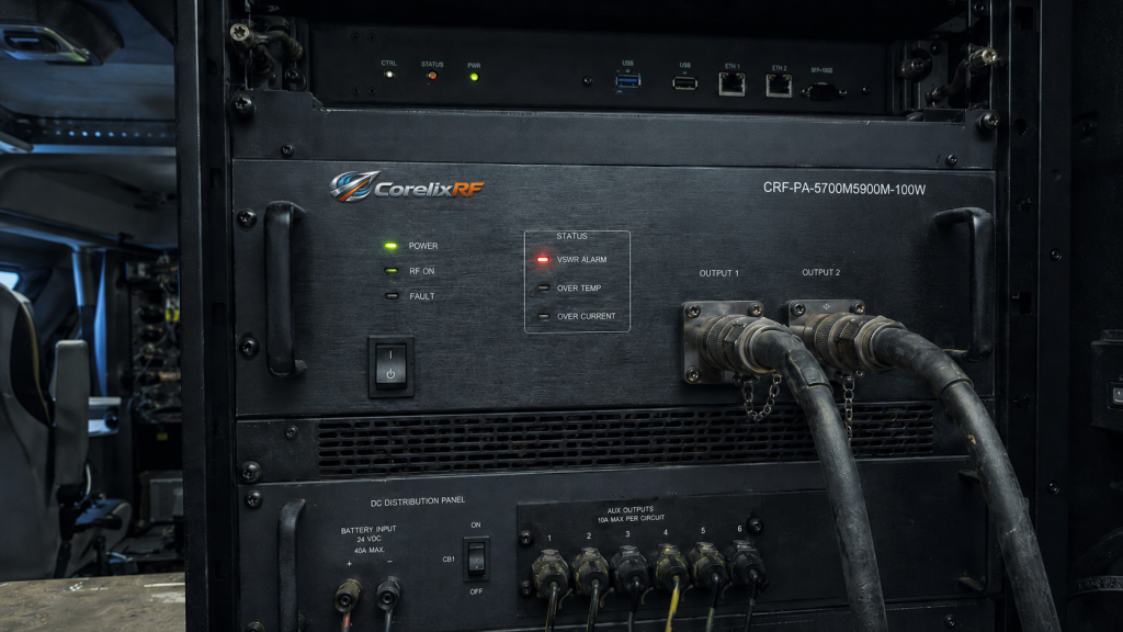
When high-power continuous wave (CW) passes through these defective junctions, intense localized heating occurs. Solder joints melt under extreme thermal loads, and metal surfaces oxidize rapidly due to microscopic arcing. The connection instantly becomes a high-impedance barrier, severing the defense link without warning.
4. How Does Thermal Expansion Destroy RF Connector Integrity?
Field deployment means vehicles endure severe daily temperature swings, while high-power CW transmission generates massive internal heat loads. Dictated by thermodynamic laws, different materials expand at vastly different rates: brass connector bodies expand much faster than beryllium copper center pins, while PTFE dielectrics swell significantly under thermal stress.
This mismatched expansion destroys precise internal geometries, creating microscopic air gaps between mating metal surfaces and altering the transmission line’s capacitance. The characteristic impedance rapidly shifts away from 50 ohms, sparking internal arcing and carbonized short circuits, ultimately leading to physical failure.
| Mechanical Tolerance Deviation | Dielectric Air Gap | Resulting VSWR |
| 0.01 mm | None | 1.1:1 |
| 0.05 mm | 0.02 mm | 1.5:1 |
| 0.10 mm | 0.05 mm | 3.0:1 |
5. Why Do Perfect Lab Results Fail Miserably in the Field?
Lab testing typically occurs in perfect climate-controlled environments using precisely calibrated Vector Network Analyzers (VNA) and pristine, short test cables. Conversely, real-world C-UAS platforms operate on swaying masts and violently shaking vehicle chassis.
Software algorithms cannot repair broken mechanical connector pins. Only pure physical defense mechanisms separate professional-grade industrial equipment from consumer-grade assemblies. True “Engineering Truth” demands that RF hardware features underlying redundant defense designs tailored for the worst mechanical shock and thermal extremes.
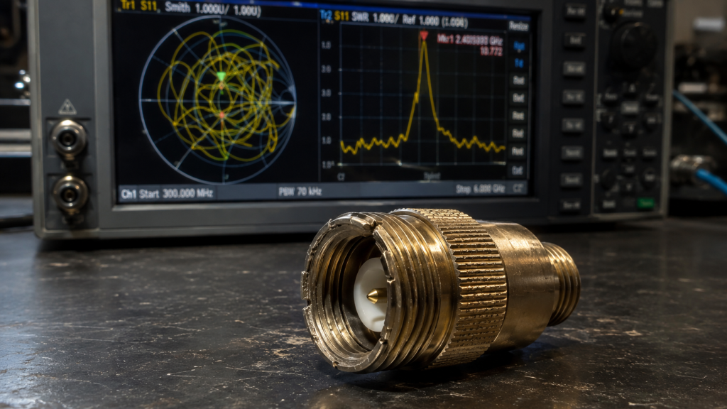
6. The Bottom-Layer System Defense of CRF-PA-5700M5900M-100W
System integrators require heavy-duty modules built for extreme battlefield survival. The CRF-PA-5700M5900M-100W by CorelixRF strips away empty marketing parameters, utilizing a pure hardware-level physical defense architecture. Even if the external antenna becomes open-circuit or cable connectors suddenly snap, the module is guaranteed against burnout and will recover rapidly once the fault is cleared.
| Operating Metric | Factory Specification | Hardware Defense Capability |
| Frequency Range | 5700 – 5900 MHz | Broadband high stability |
| Output Power | 100 Watts CW | Uninterrupted CW transmission |
| VSWR Tolerance | Infinite (Open/Short) | 100% hardware-level isolation |
7. The Core Engineering Function of the Internal Microwave Isolator
The internal microwave isolator acts as a one-way “RF valve.” Forward energy passes through this magnetic barrier with minimal loss, while all destructive reflected energy returning from a mismatched antenna is ruthlessly blocked and redirected into an industrial-grade, high-power Dummy Load.
These destructive RF energies are converted into controllable thermal energy and safely dissipated through a massive aluminum heatsink base. This provides absolute physical isolation for the fragile output transistors. This defense mechanism, rooted in magnetic physics, handles severe impedance mismatches while ensuring the continuity of communication jamming.
8. The Underlying Logic of Microsecond-Level Hardware VSWR Protection
While massive dummy loads provide the first line of defense, extreme and sustained total reflection requires active electronic intervention. This is where architectural choices dictate survival.
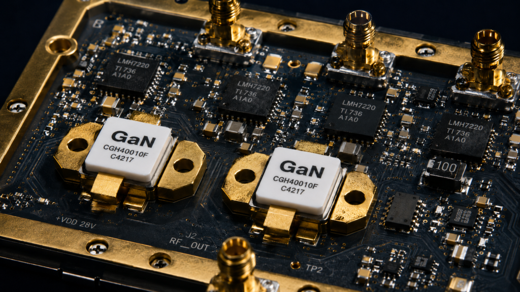
Unlike software-based digital microprocessors that introduce dangerous millisecond-level polling delays, the CRF-PA-5700M5900M-100W employs pure analog directional couplers to continuously monitor forward and reverse power. Because reflected voltage antinodes can physically pierce transistors within microseconds, our high-speed analog comparators cut gate bias voltages in under 2 microseconds (< 2 μs) upon detecting threshold violations. In battlefield deployments, lightning-fast hardware-level analog cutoff will always outlast software protection programs.
| Protection Mechanism | Reaction Time | System Survival Probability |
| Software Digital Polling | 50 – 100 ms | Very Low (Prone to Burnout) |
| Basic Comparator Circuit | 5 – 10 ms | Moderate |
| CorelixRF Analog Cutoff | < 2 μs | Extremely High (Guaranteed) |
9. Why Strict Adherence to Physical Factory Specifications is Mandatory
Many commercial suppliers dangerously “overclock” amplifiers by raising supply voltages to fake impressive paper specs in clean labs. This practice rapidly destroys component lifespan and thermal stability. Inside sealed field vehicles lacking active liquid cooling, over-voltage operation guarantees transistor thermal runaway.
CorelixRF strictly obeys the voltage and current physical limits of all factory semiconductors. We do not estimate; we do not exaggerate. The power supply architecture maintains precisely specified potential differences, and measured peak currents strictly match the thermal dissipation requirements of the product data sheet. Honest engineering means respecting physical limits—the cornerstone of high-reliability systems.
| Core Parameter | Lab Design Theory | Physical Data Sheet Limit |
| Supply Voltage | 28.0 VDC | Max 28.0 VDC (No Overclocking) |
| Current Consumption | 12.0 Amps | Peak 13.5 Amps |
| Thermal Dissipation | 250 Watts | Max Limit 300 Watts |
10. Call to Action: Return to Verifiable Engineering Truth
Senior system integrators and R&D directors must demand real laboratory VNA test data, not brochures filled with marketing jargon. Do not let an inferior cable destroy your system’s reliability, and never let an unprotected power amplifier become a ticking time bomb inside your vehicle rack.
When architecting your next-generation counter-measure system, securing reliable bottom-layer hardware is critical. Contact the CorelixRF engineering team immediately to obtain the complete Data Sheet for the CRF-PA-5700M5900M-100W, and discuss system-level matching recommendations tailored to your actual deployment environment. Trust is built on engineering truth that survives brutal physical testing.
Frequently Asked Engineering Questions (FAQ)
Q1: What is VSWR in a C-UAS RF system?
A: VSWR (Voltage Standing Wave Ratio) measures the degree of impedance mismatch on an RF transmission line. High VSWR indicates that forward transmission energy is severely blocked, and a massive amount of destructive reflected energy is surging back toward your power amplifier module—this is the primary physical culprit behind burned-out RF transmission systems.
Q2: How does RF cable “insertion loss” cause hidden system failures?
A: Insertion loss not only attenuates the effective forward power reaching the antenna, but more dangerously, long cables simultaneously “eat up” the returning reflected power. This causes the VSWR detection circuit at the rack to read artificially low values, masking highly lethal reflections at the antenna end.
Q3: Why do connectors that work perfectly in the lab frequently fail in the field?
A: Violent mechanical vibrations and extreme environmental temperature fluctuations alter the microscopic physical dimensions of cheap commercial-grade connectors. At microwave frequencies like 5.8GHz, these invisible internal deformations are enough to completely destroy the 50-ohm characteristic impedance, triggering massive energy reflections.
Q4: Exactly how does thermal expansion destroy an RF link?
A: High-power Continuous Wave (CW) transmission generates significant internal heat. The different materials inside an RF connector (e.g., brass body, beryllium copper pins, PTFE dielectric) expand at different rates. Under thermal stress, these mismatched expansions create microscopic air gaps, making the system highly susceptible to high-voltage arcing and carbonized short circuits.
Q5: How does the internal Microwave Isolator protect the CRF-PA-5700M5900M-100W?
A: An isolator is a one-way “RF valve” based on magnetic physics. It allows forward signals to pass with extremely low loss, while ruthlessly redirecting all destructive reflected energy (caused by damaged external antennas or cables) into an internal, high-power Dummy Load. This energy is then dissipated as heat, providing absolute physical shielding for the fragile output transistors.
Authorized RF engineering and compliance review
For regulated RF systems, this page should be used as an engineering and compliance review path, not as a public deployment checklist. CorelixRF starts with authorization status, operating region, frequency plan, output limit, antenna interface, safety controls, thermal limits and acceptance documents.
- RFQ checklist – send the data buyers usually forget, including band, power, duty cycle, interface and test standard
- delivery documentation – check what documents can support incoming inspection, FAT review and long-term maintenance
- quality and certification review – review the quality and compliance evidence before the project moves into procurement
- RF front-end platform – compare the RF chain as a system instead of selecting one isolated module
- RF configurator – turn frequency, power, thermal and interface requirements into a first configuration brief
- case studies – review similar engineering paths before sending an RFQ
- engineering contact – send the application notes, block diagram or target specification to engineering sales
This keeps the discussion inside lawful, authorized RF programs while still giving procurement teams a clear way to request amplifier, antenna, SDR source, documentation and factory review.
Convert VSWR protection notes into amplifier requirements
VSWR alarms usually point to a full RF chain problem, not only an antenna or cable issue. Before final purchasing, define amplifier mismatch protection, output power margin, connector layout, cooling, monitoring interface and field maintenance evidence.
- RF power amplifier product families for protected broadband and band-specific systems
- Solid-state power amplifier guide for protection logic, thermal design and control interfaces
- RFQ checklist to capture VSWR limit, load condition, duty cycle and FAT test evidence
- Send the RF chain risk to CorelixRF engineering for a project-level review