
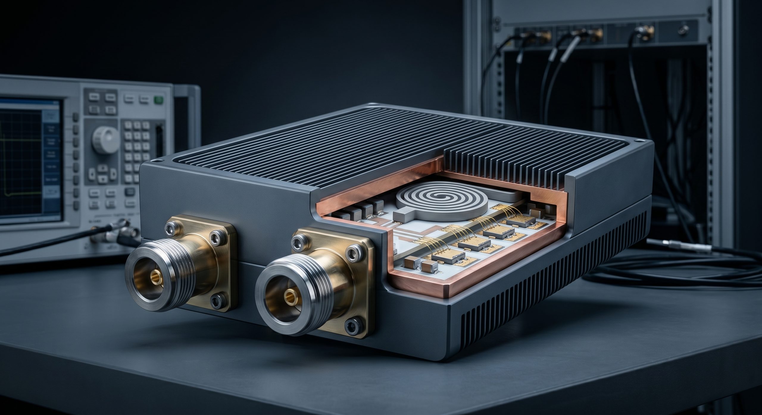
Consider the physical reality of operating high-power microwave transmitters in harsh environments. System integrators tasked with deploying counter-unmanned aerial systems (C-UAS) frequently encounter a devastating physical barrier: long-distance RF cable insertion loss combined with subpar mechanical connectors. When deploying high-frequency jammers or detection nodes in outdoor base stations, the distance between the primary RF amplifier and the radiating antenna introduces severe dielectric attenuation and phase shifts. This physical separation forces the radio frequency energy to travel through coaxial cables that inherently resist the flow of microwave power, turning expensive RF watts into wasted thermal energy. As the transmission line degrades or connectors fail due to environmental stress, the delicate 50-ohm impedance balance shatters, creating severe C-UAS VSWR alarms that halt operations immediately.
Let’s examine the raw data regarding what happens when these systems fail. A sudden impedance mismatch sends high-power RF energy reflecting directly back into the amplification stage. This reflected wave collides with the forward wave, creating massive voltage standing waves that exceed the breakdown voltage of the final stage gallium nitride transistors. Within microseconds, the active components vaporize, turning a multi-thousand-dollar RF module into a brick. This catastrophic failure means the defensive perimeter collapses, leaving the outdoor base station completely vulnerable to unauthorized drone incursions. Operating in these harsh conditions requires more than generic hardware; it demands hardware built on cold engineering truth, relying on physical protections rather than software patches to survive real-world microwave environments.
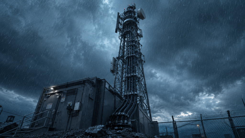
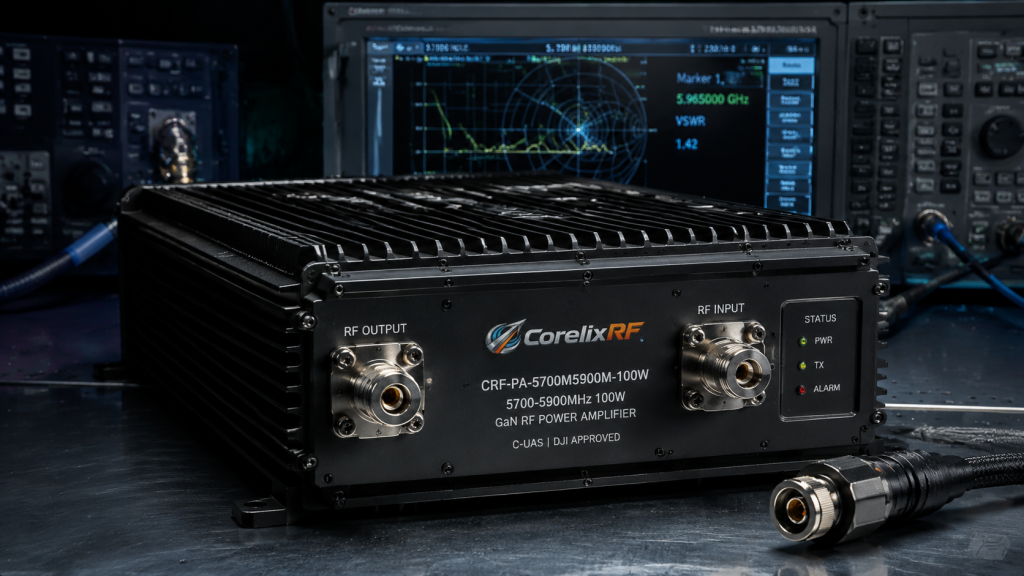
Here is the engineering truth regarding our approach to this systemic failure in high-power microwave networks. CorelixRF builds hardware specifically engineered to survive these extreme impedance mismatches and harsh environmental realities. By focusing on stringent mechanical tolerances, advanced thermal dissipation materials, ruggedized isolators, and high-speed analog VSWR protection circuits, our amplifier modules ensure continuous, uninterrupted operation regardless of external cable degradation. The CRF-PA-5700M5900M-100W stands as a primary example of this uncompromising design philosophy, engineered from the substrate up to combat the insertion loss and connector oxidation inherent in outdoor base stations. We provide system integrators with a physically indestructible RF power solution that maintains its integrity even when the external antenna array suffers catastrophic physical damage or severe moisture ingress.
Why Do Long-Distance RF Cables Trigger C-UAS VSWR Alarms in Outdoor Base Stations?
The fundamental physics dictate that pushing high-frequency radio waves through extended lengths of coaxial cable inevitably leads to severe signal degradation and impedance shifts. In outdoor base stations, system integrators often mount the radiating antennas high on towers while keeping the heavy amplification equipment in ground-level shelters. This necessitates cable runs of twenty to fifty meters. At the 5.8 GHz operating frequencies used by the CRF-PA-5700M5900M-100W, the skin effect and dielectric losses within standard corrugated copper cables cause massive power attenuation. As the cable length increases, any slight manufacturing defect in the cable’s physical structure becomes a significant source of reflection. When the forward power diminishes due to insertion loss, but reflections from distant antenna mismatches return to the source, the power detector circuitry reads an abnormally high ratio of reflected-to-forward power, instantly triggering C-UAS VSWR alarms to prevent immediate transistor burnout.
| Cable Type | Insertion Loss (dB/100ft at 5.8 GHz) | Physical Flexibility | Primary Application |
| LMR-400 | 6.8 dB | High | Short patch runs |
| 1/2″ Corrugated | 3.5 dB | Medium | Standard tower runs |
| 7/8″ Corrugated | 1.9 dB | Low | High-power main feed |
How Does Thermal Expansion and Contraction Destroy Connector Impedance?
Consider the physical reality of continuous temperature cycling on precision mechanical interfaces. Outdoor base stations undergo brutal diurnal temperature variations, shifting from freezing nights to blistering afternoon heat, particularly when subjected to direct solar loading. The RF connectors linking the main transmission lines to the amplifier outputs consist of disparate materials—typically brass, beryllium copper, and PTFE dielectrics. Because these materials possess vastly different coefficients of thermal expansion, they expand and contract at unequal rates. Over hundreds of thermal cycles, the center pins of N-type or DIN connectors slowly creep outward or retract inward, breaking the precise microscopic tolerances required to maintain a pure 50-ohm electrical impedance. This physical deformation creates a capacitive or inductive bump in the transmission line, causing immediate signal reflection and resulting in persistent C-UAS VSWR alarms that cripple the disruption capabilities of the installation.
What Role Do Cheap Connectors Play in Catastrophic Impedance Mismatch?
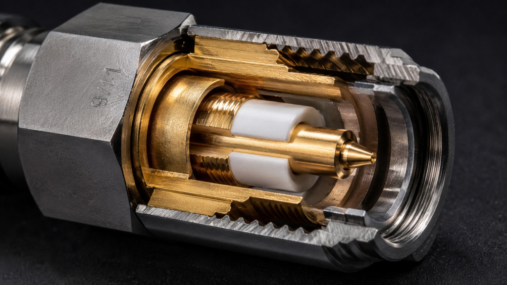
Let’s examine the raw data surrounding mechanical tolerances and their direct correlation to microwave system failure. A standard generic RF connector procured from unverified third-party vendors often features inferior plating thickness and poor machining precision. At sub-6 GHz frequencies, a surface roughness variation of just a few micrometers on the center conductor, or a poorly crimped outer shield, introduces severe parasitic inductances. When high-wattage RF energy hits these poorly machined interfaces, localized heating occurs due to increased contact resistance. This heat further degrades the cheap metallic plating, accelerating oxidation and galvanic corrosion when exposed to the humid environments typical of outdoor base stations. The resulting impedance mismatch sends a lethal spike of reflected power back down the line. Our laboratory teardowns of failed third-party systems consistently reveal that saving a few dollars on interconnects directly guarantees catastrophic C-UAS VSWR alarms under sustained load.
| Connector Component | Machining Tolerance | Surface Plating | Consequence of Failure |
| Center Pin Diameter | ±0.01 mm | Hard Gold over Nickel | Capacitive mismatch, VSWR spike |
| Outer Conductor | ±0.02 mm | Tri-Metal / Silver | Inductive bump, thermal heating |
| PTFE Dielectric | ±0.05 mm | N/A | Phase shift, impedance deviation |
Why Do Reflected Waves Vaporize Final Stage Transistors During C-UAS Operations?
The fundamental physics dictate that radio frequency energy cannot simply vanish; it must be dissipated or radiated. When an impedance mismatch occurs due to cable degradation, the forward-traveling wave bounces off the mismatched connector and travels backward toward the source amplifier. This reverse-traveling wave superimposes itself over the forward wave, creating localized regions of extreme voltage peaks along the transmission line—a phenomenon known as a standing wave. In high-power C-UAS applications, these voltage peaks easily exceed the maximum drain-to-source breakdown voltage of the final stage amplification transistors. Once the physical breakdown threshold of the semiconductor lattice is breached, the device shorts out internally. A localized plasma event occurs within the transistor packaging, melting the gold bond wires and vaporizing the active die within nanoseconds, turning a high-end amplification stage into molten slag before software-based protections can even register the event.
How Does Moisture Ingress Alter Coaxial Cable Dielectric Constants?
Consider the physical reality of weatherproofing failures in long-term outdoor deployments. Water possesses a relative permittivity (dielectric constant) of approximately 80 at room temperature, which is drastically higher than the typical 2.0 to 2.3 values of the PTFE or foam polyethylene dielectrics used in standard RF transmission lines. When micro-fractures develop in a cable’s outer UV-resistant jacket, or when connector sealing tape degrades over time, capillary action draws moisture deep into the internal coaxial structure. The introduction of water fundamentally alters the distributed capacitance of the cable, violently shifting the characteristic impedance away from the required 50 ohms. As the RF wave propagates through this water-logged section, it hits a massive impedance wall, causing total signal reflection. This environmental reality is a primary driver of unavoidable C-UAS VSWR alarms, proving that mechanical weatherproofing is just as vital as the active electronics.
| Material | Relative Permittivity (εr) | Environmental Status | System Impact |
| Solid PTFE | 2.10 | Dry / Nominal | Perfect 50-ohm match |
| Foam Polyethylene | 1.50 | Dry / Nominal | Perfect 50-ohm match |
| Pure Water | 80.1 | Moisture Ingress | Massive mismatch, severe VSWR |
Why is Real-Time Forward and Reflected Power Monitoring Mandatory?
Here is the engineering truth behind protecting expensive RF infrastructure: passive survival is not enough; active analog intervention is required. To prevent hardware destruction during sudden mismatch events, the amplifier must continuously sample the radio frequency waves traveling in both directions. This is achieved through the integration of high-directivity microstrip directional couplers coupled with ultra-fast Schottky diode detectors. These components continuously measure the precise millivolt analogs of the forward transmitting power and the returning reflected power. If the ratio exceeds a physically safe threshold, the hardware must act autonomously. Relying on digital telemetry polling or software-based intervention introduces too much latency; by the time the microprocessor registers the C-UAS VSWR alarms, the final stage transistors have already exceeded their thermal limits. Only hardwired, analog automatic level control loops can clamp the input drive fast enough to save the amplification circuitry.
How Does the CRF-PA-5700M5900M-100W Survive Extreme VSWR Conditions?
Let’s examine the raw data regarding the specific defensive architecture built into the CRF-PA-5700M5900M-100W. To directly counter the persistent threat of long-distance RF cable insertion loss and poor connectors in outdoor base stations, CorelixRF engineered this specific module with heavy-duty internal isolators. An isolator functions as a microwave one-way valve, allowing high-power forward energy to pass toward the antenna while simultaneously diverting any incoming reflected energy into an internal 50-ohm beryllium oxide termination load. By physically absorbing the reflected power before it can reach the sensitive drain terminals of the final stage transistors, the module continues to operate safely even if the external antenna is completely severed. This brute-force mechanical and electrical isolation guarantees that our hardware ignores catastrophic external mismatches, actively suppressing lethal voltage standing waves while simultaneously sending clean telemetry data to the system integrator’s central command node.
| Protective Component | Activation Time | Power Handling Capacity | Defensive Function |
| Internal Isolator | 0 nanoseconds (Passive) | 100W Continuous | Absorbs 100% reflected power |
| Schottky Detector Diode | <1 microsecond | N/A | Measures forward/reverse ratio |
| Analog ALC Loop | <5 microseconds | N/A | Clamps RF drive to safe levels |
What Lab Data Proves Our Thermal Management Mitigates VSWR Degradation?
The fundamental physics dictate that dissipating reflected RF energy generates immense, highly concentrated heat. When the internal isolator of the CRF-PA-5700M5900M-100W absorbs reflected power during severe C-UAS VSWR alarms, that energy instantly converts into thermal load at the termination resistor. To manage this extreme physical stress, CorelixRF utilizes advanced copper-tungsten alloy baseplates and pure oxygen-free copper heat spreaders directly beneath the high-stress components. Our laboratory thermal imaging confirms that even under continuous 100% reflection (an open or short circuit condition), the thermal gradient across the amplifier substrate remains strictly within the safe operating area of the internal components. By maintaining low junction temperatures through aggressive physical heat sinking, we ensure the unit does not enter thermal runaway. This rigorous thermal management physically prevents the degradation of RF performance, ensuring continuous jamming or signaling capability during active perimeter breaches.
How Do We Engineer the Output Connectors for Outdoor Base Stations?
Consider the physical reality of standard off-the-shelf connectors failing under the mechanical strain of thick outdoor transmission lines. CorelixRF utterly rejects generic, mass-produced interfaces. For the CRF-PA-5700M5900M-100W, we utilize custom-machined, heavy-flange connectors bolted directly to the primary structural housing of the amplifier, rather than relying on fragile circuit board traces to bear the mechanical load. Our center pins feature thick hard-gold plating over a proprietary nickel barrier to completely eliminate the risk of galvanic corrosion when mating with dissimilar metals in humid outdoor environments. Furthermore, the connector housings are machined from solid brass and plated with high-purity silver to minimize skin-effect losses at 5.8 GHz. By strictly controlling the mechanical mating tolerances and requiring specific torque limits during installation, our hardware mechanically guarantees a pristine 50-ohm transition, eliminating the root causes of connector-induced impedance mismatches.
| Interface Type | Coupling Nut Torque | Mating Cycles Rated | Contact Resistance |
| N-Type Female | 1.1 to 1.7 N·m | >500 Cycles | < 1.0 Milliohms |
| SMA Female | 0.9 to 1.1 N·m | >500 Cycles | < 2.0 Milliohms |
| DIN 7/16 | 25 to 30 N·m | >500 Cycles | < 0.4 Milliohms |
Why Must System Integrators Prioritize RF Insertion Loss Budgets?
Here is the engineering truth that defines successful field deployments: RF power generated at the amplifier is useless if it never reaches the radiating element. System integrators building outdoor base stations must mathematically account for every fraction of a decibel of insertion loss introduced by coaxial cables, lightning arrestors, and bulk-head adapters. Failing to calculate an accurate RF budget leads to undersized amplification and a higher susceptibility to C-UAS VSWR alarms. When integrators attempt to compensate for extreme cable loss by simply pushing the amplifier harder, they drive the active devices closer to saturation, dramatically reducing the linearity and operating lifespan of the system. Integrators must select ultra-low-loss corrugated hardline cables, utilize the shortest possible physical routing, and integrate hardware like the CRF-PA-5700M5900M-100W, which provides robust, guaranteed output power right at the flange to overcome the unavoidable physics of microwave attenuation.
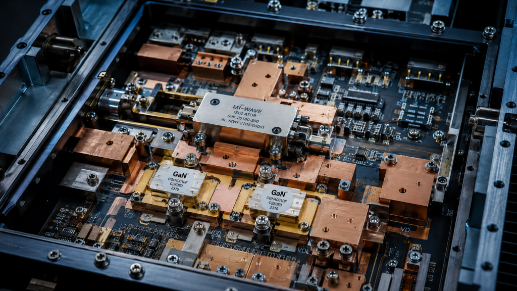
The physical realities of deploying high-frequency microwave systems in unforgiving environments cannot be bypassed through clever marketing or software patches. Overcoming the severe engineering pain points of long-distance RF cable insertion loss and poor-quality connectors requires strict adherence to material science and microwave engineering principles. C-UAS VSWR alarms in outdoor base stations are a symptom of mechanical failure, thermal degradation, and inadequate hardware protection. CorelixRF approaches these problems through the lens of pure engineering truth. By utilizing heavy-duty internal isolators, high-speed analog protection circuits, and structurally reinforced mechanical interfaces, the CRF-PA-5700M5900M-100W delivers unstoppable RF power despite catastrophic external line failures. We refuse to compromise on the physical integrity of our B2B manufacturing process. System integrators and R&D directors requiring unyielding hardware reliability must base their architectural decisions on proven laboratory data and rigorous mechanical tolerances. Contact the CorelixRF engineering team today to request the official Data Sheet for the CRF-PA-5700M5900M-100W and secure your physical RF infrastructure.
Frequently Asked Questions
Q1: What is the maximum acceptable insertion loss for cables connected to the CRF-PA-5700M5900M-100W?
A1: The physical limit depends on the required radiated power at the antenna. However, engineering best practices dictate keeping total cable insertion loss below 3 dB to ensure at least half the generated RF power actually reaches the radiating element, minimizing thermal stress on the transmission line.
Q2: Can the CRF-PA-5700M5900M-100W survive an infinite VSWR event?
A2: Yes. The internal circulator and beryllium oxide termination load are mechanically sized to absorb 100% of the reflected power. The module will survive an open or short circuit on the output port indefinitely, provided the baseplate thermal dissipation limits are respected.
Q3: Why does CorelixRF mandate specific torque wrench settings for output connectors?
A3: Proper torque ensures a flush, gas-tight mechanical mate between the center pin and the outer shielding. Deviating from the specified torque limits introduces microscopic air gaps, altering the local dielectric constant and instantly generating high-frequency impedance mismatches that trigger C-UAS VSWR alarms.
Q4: How does extreme cold affect the VSWR readings in outdoor base stations?
A4: Extreme cold causes the copper conductors and PTFE dielectrics in external cables to contract mechanically. This physical shrinkage pulls connectors apart slightly, changing the electrical length and the characteristic impedance, leading to increased reflected power if the connectors are not properly rated for severe thermal cycling.
Q5: Does CorelixRF provide customization for different frequency bands using the same ruggedized architecture?
A5: Yes. While the CRF-PA-5700M5900M-100W is optimized for specific interference bands, our core engineering architecture—including the heavy-flange connectors, analog protection loops, and massive thermal spreaders—is actively adapted for various frequency ranges to meet the exact physical specifications of global system integrators.
Authorized RF engineering and compliance review
For regulated RF systems, this page should be used as an engineering and compliance review path, not as a public deployment checklist. CorelixRF starts with authorization status, operating region, frequency plan, output limit, antenna interface, safety controls, thermal limits and acceptance documents.
- RFQ checklist – send the data buyers usually forget, including band, power, duty cycle, interface and test standard
- delivery documentation – check what documents can support incoming inspection, FAT review and long-term maintenance
- quality and certification review – review the quality and compliance evidence before the project moves into procurement
- RF front-end platform – compare the RF chain as a system instead of selecting one isolated module
- RF configurator – turn frequency, power, thermal and interface requirements into a first configuration brief
- case studies – review similar engineering paths before sending an RFQ
- engineering contact – send the application notes, block diagram or target specification to engineering sales
This keeps the discussion inside lawful, authorized RF programs while still giving procurement teams a clear way to request amplifier, antenna, SDR source, documentation and factory review.
RF Engineering Review Path for Outdoor VSWR Risk
For outdoor RF sites where VSWR alarms point to connector, load or amplifier stress, review the RF power amplifier platform options together with RF front-end platform planning before sending requirements through the RF inquiry form. This helps CorelixRF check frequency band, output power, duty cycle, antenna/load condition and protection evidence before quotation.