
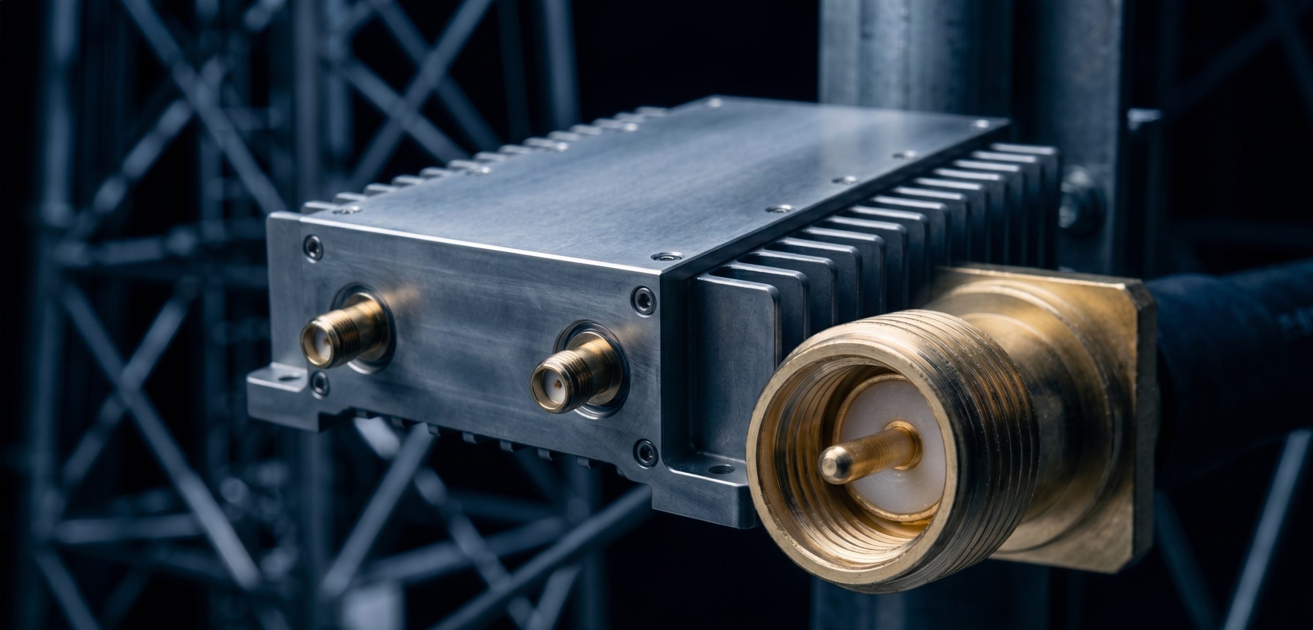
System integrators face a brutal reality when deploying high-frequency countermeasures in harsh outdoor environments. The primary engineering failure point in Prison Jamming Tower Broadband Signal Blocking arrays is rarely the core active components inside the control room, but rather the catastrophic degradation of the RF transmission path. Engineers run hundreds of feet of coaxial cable up massive steel structures, subjecting the entire network to extreme mechanical strain and environmental weathering. Over extended distances, severe cable insertion loss decimates the effective radiated power before the signal even reaches the transmission antennas. Worse, system integrators often source commercial-grade coaxial connectors that lack the precision machining required for microwave frequencies, leading to structural fatigue under constant wind load and vibration.

This mechanical degradation causes severe impedance mismatch at the antenna junctions, forcing massive amounts of RF energy to reflect directly down the line. The standing waves generate concentrated thermal pockets that literally melt dielectric insulators and systematically burn out final stage power transistors inside the base station. When the hardware fails, the facility’s security perimeter immediately collapses, creating dangerous blind spots in the jamming coverage. Relying on inadequate physical infrastructure guarantees system failure when the facility needs continuous operational security the most.
Here is the engineering truth… CorelixRF manufactures hardware designed to survive these exact physical realities. We engineer high-frequency power amplifiers that account for the inevitable losses of long transmission lines, delivering guaranteed power to the radiating elements. By integrating the CRF-PA-18G40G-20W directly at the tower apex or utilizing our precision-machined interconnects, integrators eliminate the variable failure points of inferior mechanical components. CorelixRF builds systems based strictly on laboratory data and physical limits, providing the defense industry with the only viable defense against microwave path degradation.
Why Do RF Cables Fail Catastrophically in Prison Jamming Towers?
Consider the physical reality… the vertical deployment of thick, heavy RF coaxial cables up a fifty-meter steel structure introduces massive gravitational strain on the copper shielding and the central conductor. Engineers frequently secure these cables using standard localized clamps, which deform the outer jacket and crush the internal dielectric material. This mechanical deformation permanently alters the precise concentricity required to maintain a fifty-ohm characteristic impedance, immediately creating localized reflection points along the transmission line. When generating Prison Jamming Tower Broadband Signal Blocking frequencies, particularly in the upper spectrum ranges, these microscopic deformities compound the overall return loss of the system. Furthermore, continuous wind load creates micro-vibrations that travel the entire length of the cable run, slowly fatiguing the solid copper center conductors at the connector junctions. Over a period of several months, the copper hardens and eventually snaps inside the connector housing, leading to an instantaneous open circuit. The amplifier continues to transmit full power into an open load, generating massive voltage standing wave ratios that will destroy standard commercial amplifiers within milliseconds if proper isolation is not physically integrated into the system architecture.
What Physics Drive Long-Distance Insertion Loss at High Frequencies?
The fundamental physics dictate… that as frequency increases into the millimeter-wave spectrum, the skin effect forces the electromagnetic signal to travel strictly along the outermost molecular layer of the inner conductor. Any microscopic surface oxidation, rough machining, or plating imperfections will exponentially increase the resistive losses of the transmission line. When running fifty to one hundred feet of cable up a vertical mast, the native attenuation of even premium corrugated copper cables severely depletes the output power before the signal reaches the antenna array. An amplifier pushing twenty watts at the base station might only deliver two watts at the antenna input, completely invalidating the link budget required for effective security perimeters. Integrators must calculate the physical limit of the dielectric material’s tangent loss, which becomes the dominant factor of power dissipation above eighteen gigahertz. The thermal conversion of RF energy within the cable limits the maximum continuous wave power handling, making remote mounted amplifier configurations absolutely necessary. CorelixRF addresses this physical limitation by engineering the CRF-PA-18G40G-20W for direct mast-mount integration, bypassing the extensive cable runs and delivering true calculated power straight into the radiating elements.
| Cable Type (1/2″ Corrugated) | Frequency | Attenuation (dB/100ft) | Power Loss Factor | Effective Range Impact |
| Standard Dielectric | 18.0 GHz | 12.4 dB | 94.2% Dissipated | Severe Degradation |
| Precision Air-Dielectric | 18.0 GHz | 8.1 dB | 84.5% Dissipated | High Degradation |
| Standard Dielectric | 40.0 GHz | 24.5 dB | 99.6% Dissipated | Complete Signal Loss |
| Precision Air-Dielectric | 40.0 GHz | 16.2 dB | 97.6% Dissipated | Complete Signal Loss |
How Does Impedance Mismatch from Inferior Connectors Destroy Transistors?
Let’s examine the raw data… provided by continuous wave operation stress tests performed on generic field-terminated SMA and 2.92mm connectors. The physical geometry of an RF connector dictates its characteristic impedance, and any deviation in the pin depth or dielectric seating alters the capacitive and inductive balance of the junction. Inferior connectors manufactured with loose mechanical tolerances suffer from pin protrusion or recession when subjected to torque, immediately causing a severe impedance mismatch at the boundary layer. When a twenty-watt continuous wave signal encounters this mismatch, the unabsorbed energy reflects backward toward the amplifier, creating a standing wave that doubles the peak voltage across the final stage Gallium Nitride transistors. This extreme voltage spike exceeds the absolute maximum rating of the semiconductor drain-source junction, triggering localized electron avalanche breakdown and catastrophic thermal runaway. CorelixRF utilizes exact laboratory matching networks and high-isolation internal circulators to absorb these inevitable reflections. We specify strict pin-depth tolerances using precision gauges, ensuring that the physical interface does not become the weak link that destroys thousands of dollars of active microwave electronics during continuous operation.
Where Do Mechanical Tolerances Compromise Broadband Signal Blocking?
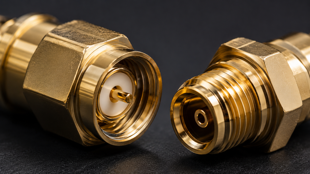
The physical dimensions of a microwave connector are strictly dictated by the wavelength of the frequencies they transmit, meaning that at forty gigahertz, a mechanical deviation of a fraction of a millimeter creates massive electrical consequences. When system integrators procure non-spec connectors for field repairs on a jamming array, they introduce mechanical step-discontinuities into the signal path. These discontinuities act as reactive filters, completely altering the phase and amplitude linearity of the transmitted noise spectrum. A system designed to project a flat white noise floor across an entire band will instead exhibit deep nulls and severe ripples, allowing specific threat frequencies to bypass the interference field entirely. The mechanical integrity of the mating surfaces also dictates the passive intermodulation performance of the entire tower. Dissimilar metals or poor electroplating will oxidize in the outdoor environment, creating microscopic diode junctions that mix high-power carrier waves and generate spurious emissions that interfere with friendly communication channels. CorelixRF enforces strict manufacturing tolerances and aerospace-grade plating standards to maintain absolute linearity and physical consistency across the entire operating spectrum, guaranteeing zero degradation in the noise profile.
| Mechanical Parameter | CorelixRF Standard | Commercial Grade | RF Impact at 40 GHz |
| Pin Depth Tolerance | +0.000 to -0.005 in | ±0.015 in | Severe VSWR Spikes |
| Surface Finish | 4 micro-inches | 16 micro-inches | High Insertion Loss |
| Plating Material | Gold over Nickel | Silver/Tin Alloy | Passive Intermodulation |
| Concentricity | 0.001 in TIR | 0.005 in TIR | Phase Distortion |
Can Thermal Expansion and Contraction Cause Sudden Connector Shearing?
Consider the physical reality… of a steel tower exposed to extreme environmental temperature fluctuations throughout a continuous operational year. The thick copper outer conductors of the transmission lines possess a vastly different coefficient of thermal expansion compared to the steel mounting brackets and the aluminum alloy connector housings. As the sun heats the outer black polyethylene jacket to extreme temperatures during the day, the copper expands linearly, pushing the internal center conductor forward. At night, freezing temperatures cause rapid contraction. This daily cyclical movement exerts thousands of pounds of sheer force across the delicate dielectric beads and solder joints inside the connector assemblies. Over several seasons, this constant mechanical fatigue literally shears the solder joints away from the brass housings, disconnecting the center pin completely. CorelixRF mitigates this inevitable physical failure by engineering specific strain relief geometries into our equipment interfaces and recommending exact mechanical torque specifications for all external connections. We test our integrated modules inside environmental thermal chambers, simulating decades of thermal cycling to guarantee that the mechanical integrity of our output stages will never yield to the fundamental physics of thermal expansion.
Why is Laboratory Data the Only Metric for True Microwave Electronics?
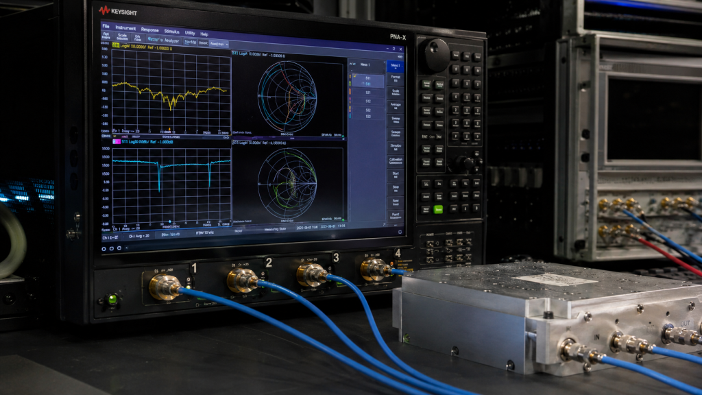
Here is the engineering truth… commercial marketing materials generated by generic suppliers frequently quote theoretical peak power figures derived from low-frequency semiconductor data sheets, entirely ignoring the physical realities of high-frequency integration. True microwave engineering requires rigorous empirical testing utilizing calibrated Vector Network Analyzers, power meters, and massive thermal heat sinks to establish the actual continuous operational limits of a specific design. When constructing Prison Jamming Tower Broadband Signal Blocking arrays, relying on theoretical data guarantees field failure. The complex parasitic capacitances and inductances present in the physical layout of a printed circuit board drastically reduce the efficiency and output power of the final amplifier module. CorelixRF rejects simulated performance metrics in favor of raw laboratory data captured under extreme stress conditions. We document exact current consumption, forward power, and gain flatness across the entire eighteen to forty gigahertz spectrum while operating at maximum thermal capacity. We present this unvarnished data to system integrators, providing them with the exact physical parameters they need to design cooling systems and calculate accurate link budgets for long-distance perimeter defense.
How Does the CRF-PA-18G40G-20W Defend Against Mechanical Stress?
The physical architecture of the CRF-PA-18G40G-20W is specifically designed to isolate the sensitive Gallium Nitride monolithic microwave integrated circuits from external kinetic forces and environmental degradation. The entire amplifier module is CNC machined from a solid block of aerospace-grade aluminum alloy, creating a rigid Faraday cage that prevents physical distortion of the internal microstrip transmission lines. We utilize proprietary glass-to-metal sealed coaxial feedthroughs for all RF input and output ports, physically isolating the external connector strain from the delicate gold wire bonds connecting the semiconductor die to the circuit board. If a massive mechanical shock or thermal contraction event shears the external connector, the internal hermetic seal remains entirely intact, protecting the core electronics from moisture ingress and atmospheric contamination. Furthermore, the thick aluminum chassis acts as a massive thermal spreader, pulling heat away from the active devices and distributing it evenly across the external mounting surface. This heavy-duty mechanical design guarantees that the physical infrastructure will survive the brutal realities of tower deployment, maintaining continuous operation regardless of the external environmental stressors.
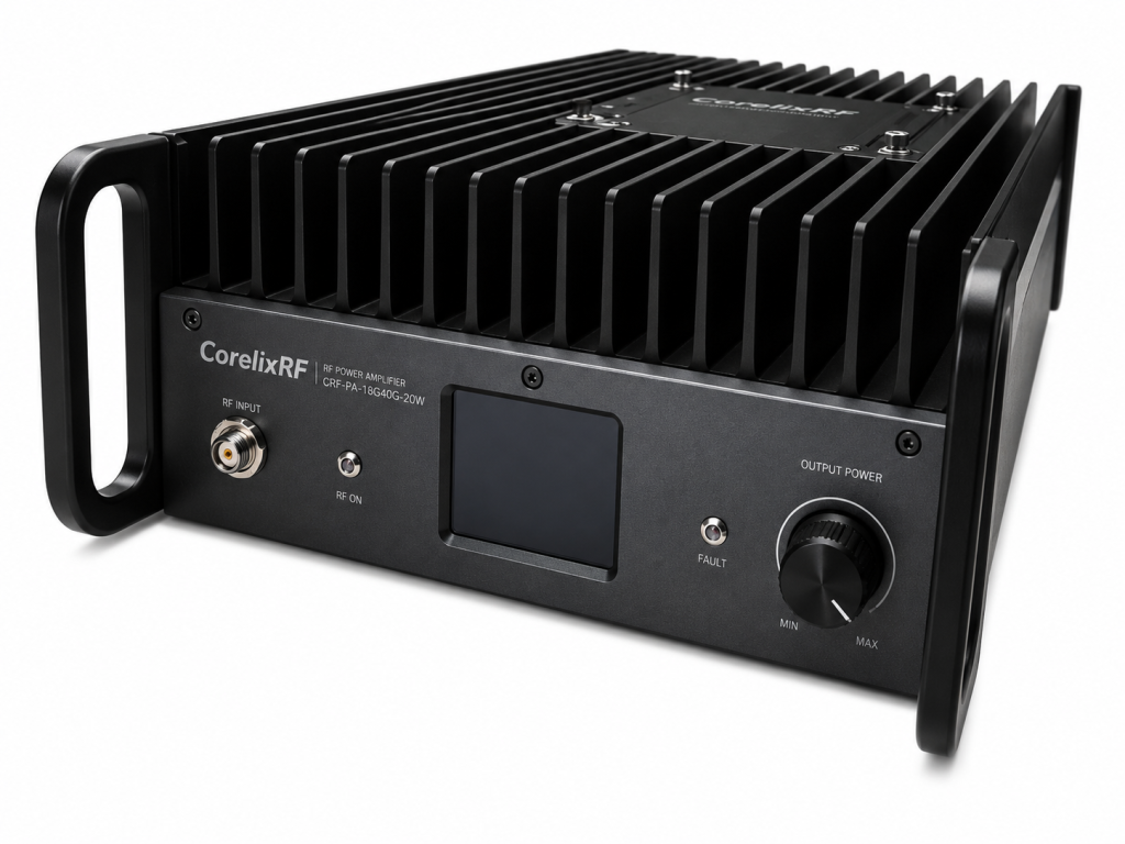
| Specification | CRF-PA-18G40G-20W Data | Laboratory Condition | Limit Justification |
| Frequency Range | 18.0 GHz to 40.0 GHz | Calibrated VNA | Full Spectrum Coverage |
| Saturated Power | 20 Watts (43 dBm) Min | Continuous Wave | Maximum Output verified |
| Gain Flatness | ± 2.5 dB | Full Temperature Range | Ensure Linear Noise Floor |
| Input VSWR | 1.5:1 Maximum | 50 Ohm Reference | Minimize Reflected Power |
What Are the Real Voltage and Current Limits for 18-40 GHz Power Amplifiers?
Let’s examine the raw data… regarding the DC power consumption necessary to generate continuous wideband microwave energy. High-frequency Gallium Nitride devices operate at significantly higher voltages than legacy silicon laterally diffused metal oxide semiconductors, typically requiring twenty-eight to thirty-two volts at the drain terminal. Generating twenty watts of RF power across the eighteen to forty gigahertz spectrum operates at roughly fifteen to twenty percent power added efficiency, meaning the system must draw massive amounts of direct current while dissipating the remaining energy as pure heat. The CRF-PA-18G40G-20W requires a strictly regulated power supply capable of delivering sustained high amperage without voltage droop during peak load conditions. If the external power supply cannot maintain the specific current and voltage parameters, the internal bias networks will drift, immediately compromising the linearity and output power of the module. CorelixRF implements ruggedized internal power conditioning circuits to filter voltage spikes and stabilize the drain current, preventing the external electrical supply fluctuations from destroying the precise biasing required for the microwave transistors to function correctly.
| Material | Coefficient of Thermal Expansion | Impact on RF Hardware | Failure Mode |
| Copper (Outer Conductor) | 16.6 µm/(m·K) | High Expansion Rate | Solder Joint Stress |
| Aluminum (Chassis) | 22.2 µm/(m·K) | Very High Expansion | Housing Distortion |
| PTFE (Dielectric Bead) | 112.0 µm/(m·K) | Extreme Expansion | Internal Pin Displacement |
| Kovar (Hermetic Seals) | 5.5 µm/(m·K) | Stable Reference | Maintains Vacuum Integrity |
Why Do Integrators Ignore VSWR Degradation in Outdoor Deployments?
The fundamental physics dictate… that any degradation in the antenna system will immediately manifest as a rising Voltage Standing Wave Ratio at the amplifier output port. In outdoor tower environments, antennas accumulate ice, moisture, and particulate matter, which detunes their precise resonant frequency and drastically alters their characteristic impedance. Many system integrators deploy commercial amplifiers that lack sufficient internal isolation, falsely assuming the initial dry-weather installation metrics will remain constant. When heavy rain coats the antenna radome, the resulting impedance mismatch forces severe reflected power back down the transmission line, compounding the insertion loss issues and overloading the active components. The continuous high-voltage standing waves degrade the dielectric integrity of the coaxial cables and physically stress the connector junctions, accelerating the mechanical fatigue we previously discussed. CorelixRF designs heavy-duty isolators into our deployment topologies, acting as an electrical check-valve that absorbs these inevitable environmental reflections. We engineer the system to handle the physical reality of detuned outdoor antennas, ensuring the amplifier continues to project maximum forward power without succumbing to the destructive feedback loops caused by weather degradation.
How Do We Ensure Continuous 20W Output Across the Entire Spectrum?
Generating a stable twenty watts of continuous wave power across a massive twenty-two gigahertz bandwidth requires extreme precision in the physical layout of the matching networks. Traditional amplifier designs utilize narrowband reactive matching, which physically limits the power transfer to a very specific frequency range. To achieve true broadband performance for Prison Jamming Tower Broadband Signal Blocking arrays, CorelixRF utilizes distributed amplifier topologies and spatial power combining techniques on the physical circuit board. We precisely machine the microstrip transmission lines to exact physical lengths, utilizing the inherent capacitance and inductance of the copper traces to absorb the parasitic elements of the Gallium Nitride transistors. This physical geometry requires absolute dimensional stability; any warping of the printed circuit board under thermal load will immediately alter the trace impedance and destroy the gain flatness. Our solid aluminum housing provides the immense structural rigidity required to keep the microwave substrates perfectly flat under extreme thermal stress. We verify this continuous power output using laboratory thermal cameras and calibrated power meters, ensuring the hardware delivers the exact specified wattage across every megahertz of the operational band.
| VSWR Ratio | Reflected Power % | Transmitted Power % | Impact on CorelixRF Amplifier |
| 1.0:1 | 0.0% | 100.0% | Ideal Operating Condition |
| 1.5:1 | 4.0% | 96.0% | Normal Safe Operation |
| 2.0:1 | 11.1% | 88.9% | Minor Thermal Increase |
| 3.0:1 | 25.0% | 75.0% | Safely Absorbed by Isolator |
Conclusion
The mechanical deployment of high-frequency RF systems demands an absolute adherence to the laws of physics and materials science. When system integrators attempt to bypass these physical realities by utilizing commercial-grade cables and inferior mechanical connectors, they guarantee the catastrophic failure of the entire security perimeter. The extreme insertion loss, severe impedance mismatches, and unavoidable thermal shear forces will systematically destroy active components and neutralize the effective jamming coverage. CorelixRF builds the CRF-PA-18G40G-20W precisely to counter these exact mechanical and electrical failures. We prioritize engineering truth over theoretical marketing, delivering ruggedized, precision-machined hardware that survives the brutal realities of tower-mounted deployments. Do not compromise your critical infrastructure with fragile, unverified components that will shear under environmental load. Contact the CorelixRF engineering team today to request the official laboratory data sheet and verify the physical limits of our microwave manufacturing capabilities.
Frequently Asked Questions (FAQ)
Q1: Why is the insertion loss of coaxial cables so severe at 40 GHz?
At frequencies reaching forty gigahertz, the electromagnetic energy travels entirely on the microscopic outer layer of the conductor due to the skin effect. The native resistance of the copper, combined with the extreme dielectric losses of the internal insulating material, converts the vast majority of the RF energy directly into heat before it reaches the end of the cable run.
Q2: How does CorelixRF ensure the CRF-PA-18G40G-20W withstands thermal expansion?
We CNC machine the amplifier chassis from solid blocks of aerospace-grade aluminum and utilize proprietary glass-to-metal hermetic seals for the RF connectors. This physical isolation prevents the massive shear forces generated by expanding external copper cables from transferring to the delicate gold wire bonds inside the monolithic microwave integrated circuit package.
Q3: What happens if an inferior connector causes a severe impedance mismatch?
A mechanical discrepancy in a connector immediately alters its characteristic fifty-ohm impedance, causing the high-power RF signal to reflect backward. This reflected energy creates a massive voltage standing wave that can instantly exceed the absolute maximum drain-source voltage rating of the Gallium Nitride transistors, resulting in permanent thermal destruction.
Q4: Why should system integrators avoid theoretical data sheets?
Theoretical performance metrics ignore the complex physical realities of high-frequency circuit integration, such as trace parasitic capacitance, mechanical tolerances, and thermal degradation. CorelixRF provides raw laboratory data captured from physical Vector Network Analyzers and power meters under extreme continuous wave stress testing, ensuring our specifications reflect actual field performance.
Q5: Can the CRF-PA-18G40G-20W operate continuously into an open circuit?
Operating a high-power amplifier into a completely open circuit generates maximum reflected power. While CorelixRF specifies strict internal isolation and ruggedized bias networks to protect the active devices from VSWR degradation, continuous operation into a completely sheared connector requires external high-power isolators to physically absorb and dissipate the reflected thermal load.
Authorized RF engineering and compliance review
For regulated RF systems, this page should be used as an engineering and compliance review path, not as a public deployment checklist. CorelixRF starts with authorization status, operating region, frequency plan, output limit, antenna interface, safety controls, thermal limits and acceptance documents.
- RFQ checklist – send the data buyers usually forget, including band, power, duty cycle, interface and test standard
- delivery documentation – check what documents can support incoming inspection, FAT review and long-term maintenance
- quality and certification review – review the quality and compliance evidence before the project moves into procurement
- RF front-end platform – compare the RF chain as a system instead of selecting one isolated module
- RF configurator – turn frequency, power, thermal and interface requirements into a first configuration brief
- case studies – review similar engineering paths before sending an RFQ
- engineering contact – send the application notes, block diagram or target specification to engineering sales
This keeps the discussion inside lawful, authorized RF programs while still giving procurement teams a clear way to request amplifier, antenna, SDR source, documentation and factory review.
Turn tower RF data into a matched hardware chain
Broadband tower planning needs more than frequency lists. Match amplifier output power, antenna gain, cable loss, protection logic, cooling margin and site maintenance evidence before locking the RFQ.
- RF power amplifier product families for broadband and band-specific high-power chains
- RF antenna options for directional, sector and custom coverage planning
- RFQ checklist for band, power, duty cycle, VSWR, cooling and FAT evidence
- Send the tower RF chain to CorelixRF engineering for review