
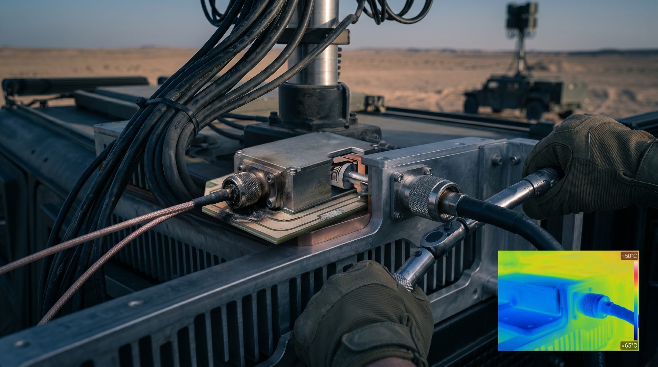
C-UAS Countermeasure Vehicle operators demand absolute performance parameters in the field. When engineering teams design these defensive platforms, they confront brutal physical realities. The primary failure mode of these systems does not occur within the digital signal processing unit; it materializes in the physical layer. Long-distance insertion loss and mechanical failure triggered by inferior connectors severely cripple the transmission path. When a 5.8GHz signal travels through a compromised coaxial run, the resulting impedance mismatch reflects power directly back into the final amplification stage. This continuous reflection burns out the primary transistors, creating immediate blind spots in the defensive perimeter. The system operator loses jamming capability precisely when a hostile drone enters the active engagement zone. CorelixRF constructs hardware designed specifically to survive these extreme conditions. We rely strictly on laboratory data, metallurgical science, and uncompromising manufacturing standards to engineer amplifier modules that endure catastrophic field variables.
Why Do Long Cable Runs Destroy Signal Integrity?
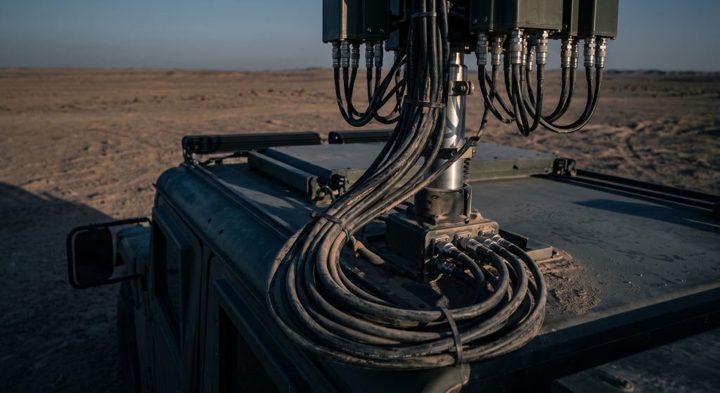
The fundamental physics dictate… that as frequency increases, the propagating signal travels closer to the surface of the conductor due to the skin effect. Vehicle-Mounted Countermeasure System Integration requires routing thick RF cables through thick steel bulkheads, around hot engine compartments, and up extending pneumatic masts. These long cable runs introduce severe insertion loss, particularly at the 5.7 to 5.9 GHz operational bands. A standard low-loss coaxial cable typically exhibits 0.5 dB of attenuation per meter at these specific frequencies. Over a 10-meter routing path, the defensive system loses 5 dB of raw output power before the signal even reaches the antenna array. This translates to roughly two-thirds of the expensive RF energy dissipating as waste heat within the cable dielectric material. System integrators routinely underestimate this physical limitation, specifying an amplifier output based on theoretical antenna gain rather than the actual power delivered to the physical feed point. This oversight severely compromises the effective radiated power (ERP) of the C-UAS Countermeasure Vehicle, reducing the effective jamming range and rendering the entire platform highly vulnerable during high-stress deployment phases.
How Does Impedance Mismatch Cause Catastrophic Failure?
Let’s examine the raw data… regarding voltage standing wave ratio (VSWR) and return loss parameters. When an RF signal encounters a physical transition point, such as a poorly terminated connector or a damaged cable segment, a significant portion of the forward wave reflects backward toward the transmission source. In a high-power scenario typical of Vehicle-Mounted Countermeasure System Integration, a VSWR of 3.0:1 means 25% of the total output power reflects directly into the amplifier stage. If a power amplifier generates 100 watts of continuous wave power, 25 watts bounce back into the final stage transistors. This reflected energy generates extreme localized heating on the semiconductor die, rapidly exceeding the maximum junction temperature limits of the active components. Thermal runaway ensues rapidly, leading to catastrophic junction failure and a completely dead RF module. Integrators must treat the entire transmission line as a single, finely tuned impedance environment, where any physical deviation from a strict 50-ohm characteristic impedance results in immediate, destructive consequences for the amplification hardware.
| VSWR Ratio | Return Loss (dB) | Reflected Power (%) | Transmitted Power (%) | Operational Status |
| 1.0:1 | Infinity | 0.0% | 100.0% | Ideal Laboratory Condition |
| 1.5:1 | 14.0 dB | 4.0% | 96.0% | Acceptable Field Deployment |
| 2.0:1 | 9.5 dB | 11.1% | 88.9% | Marginal Warning State |
| 3.0:1 | 6.0 dB | 25.0% | 75.0% | Severe Component Stress |
| Infinity | 0.0 dB | 100.0% | 0.0% | Catastrophic Open/Short |
What Happens When Inferior Connectors Experience Vibration?
C-UAS Countermeasure Vehicles operate continually in hostile terrain, subjecting the entire steel chassis to continuous, high-amplitude mechanical vibration. Commercial off-the-shelf (COTS) RF connectors lack the heavy structural integrity required for these brutal environments. When an inferior N-type or SMA connector vibrates violently over dirt roads, the center pin undergoes microscopic fretting corrosion. The thin gold plating flakes away, exposing the underlying brass or beryllium copper substrate to rapid oxidation. This mechanical degradation acts as a variable resistor within the active RF path, creating passive intermodulation (PIM) and sudden, unpredictable spikes in insertion loss. Furthermore, sustained mechanical resonance causes the threaded coupling nut to back out, physically decoupling the transmission line. A physical separation of just a few millimeters at 5.8 GHz creates a complete open circuit condition. The resulting infinite VSWR acts as a solid physical wall, reflecting 100% of the forward power back into the source amplifier. CorelixRF analyzes these mechanical failure modes directly in the laboratory, proving that standard commercial connectors guarantee total mission failure in tactical mobile deployments.
Can Thermal Expansion Sever the RF Transmission Path?
Consider the physical reality… of a counter-drone system deployed in a desert environment where daytime ambient temperatures reach 50°C, followed rapidly by sub-freezing nights. The discrete materials comprising the coaxial cables and connectors possess drastically different coefficients of thermal expansion (CTE). The polytetrafluoroethylene (PTFE) dielectric expands at a significantly higher rate than the outer copper shield and the inner conductor wire. Over multiple diurnal temperature cycles, this mismatched expansion forces the center pin of the connector to piston outward or retract inward unpredictably. If the pin retracts too far into the housing, the physical contact breaks entirely. If the pin pistons outward, it crushes the mating receptacle, permanently destroying the precision interface. This thermomechanical stress directly degrades the Vehicle-Mounted Countermeasure System Integration. The physical movement of the dielectric also alters the characteristic impedance of the cable at the connector junction, introducing massive signal reflections that the monitoring system might not detect until the amplifier operates at full transmit power, leading to immediate thermal component stress.
| Material Component | CTE (ppm/°C) | Primary Function in RF Path | Expansion Behavior |
| Polytetrafluoroethylene (PTFE) | 100.0 – 160.0 | Primary Dielectric Insulator | High expansion, causes connector pistoning |
| Beryllium Copper (BeCu) | 17.0 | Center Conductor / Pin | Moderate expansion, maintains spring tension |
| Aluminum Alloy (6061) | 23.6 | Amplifier Chassis / Heat Sink | Moderate expansion, standard structural metal |
| Stainless Steel (303) | 17.3 | Ruggedized Connector Body | Low expansion, resists physical deformation |
| Gold (Plating) | 14.2 | Surface Contact Layer | Low expansion, provides oxidation resistance |
Why Do Connector Tolerances Dictate System Reliability?
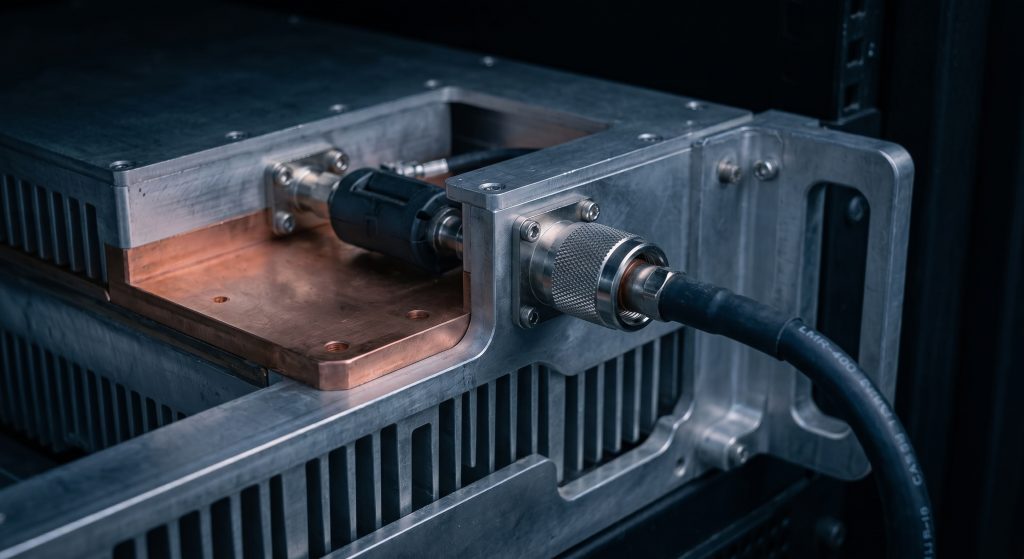
Microwave engineering demands rigorous precision machining strictly at the micron level. When manufacturing RF physical interfaces, the physical dimensions dictate the electrical performance outright. If a connector interface features an air gap of merely 0.1 millimeters due to poor factory machining tolerances, it introduces a severe capacitive discontinuity. At 5.8 GHz, this minor physical anomaly alters the phase and amplitude of the propagating wave entirely. Inferior connectors manufactured with loose mechanical tolerances often feel mechanically secure when technicians thread them together, yet they hide severe electrical mismatches internally. These microscopic gaps create intense localized hot spots within the connector body as high-power RF energy arcs across the vacuum gap. The continuous arcing carbonizes the surrounding PTFE dielectric material, transforming an insulator into a conductive carbon path. This carbonization process creates a permanent, unrecoverable short circuit across the main transmission line. System integrators must demand rigid adherence to MIL-STD-348 specifications for all connector interfaces to prevent these invisible, devastating mechanical failures from crippling the overall defense architecture.
| Tolerance Parameter | Acceptable Variance (mm) | Electrical Impact at 5.8 GHz | Consequence of Failure |
| Center Pin Concentricity | ± 0.025 | Impedance Consistency | Increased VSWR, phase distortion |
| Pin Depth / Protrusion | ± 0.050 | Capacitive / Inductive Shift | Arcing, mechanical receptacle damage |
| Dielectric Flushness | ± 0.030 | Velocity of Propagation | Impedance mismatch at mating plane |
| Thread Pitch Accuracy | ± 0.015 | Mating Pressure Stability | Loosening under severe vehicle vibration |
| Plating Thickness | ± 0.001 | Skin Effect Resistance | Increased insertion loss, oxidation |
How Does the CRF-PA-5700M5900M-100W Tolerate High VSWR?
Here is the engineering truth… regarding the CRF-PA-5700M5900M-100W module. We designed this specific hardware to anticipate the inevitable physical degradation of the external transmission lines. Knowing objectively that cables will suffer insertion loss and connectors will degrade over time, CorelixRF integrated a high-power, low-loss ferrite isolator directly at the final output stage of the internal amplifier circuit. This internal circulator acts as a strict one-way valve for microwave energy. It permits the 100 watts of forward power to exit the RF port while forcefully terminating any reflected power into a heavy-duty internal dummy load. If the external antenna cable is completely severed during an operation, resulting in an immediate open circuit, the CRF-PA-5700M5900M-100W will absolutely not burn out. The reflected energy dissipates safely as thermal heat within the machined aluminum chassis. This hardware-level protection mechanism guarantees that the primary amplification circuitry survives the worst-case mechanical failures encountered during rigorous field operations, ensuring the C-UAS Countermeasure Vehicle remains functional under severe physical duress.
What Role Does Material Science Play in CorelixRF Hardware?
The reliability of the CRF-PA-5700M5900M-100W relies heavily on applied materials science rather than standard consumer electronics assembly techniques. We strictly utilize high-thermal-conductivity copper baseplates permanently bonded to structural aluminum alloys to manage the intense heat flux generated by the active Gallium Nitride (GaN) transistors. The printed circuit boards employ advanced high-frequency laminates, such as Rogers RO4350B, which offer exceptional dimensional stability across extreme temperature gradients. This precise stability ensures that the microstrip transmission lines maintain their strict 50-ohm characteristic impedance regardless of environmental thermal soaking. Furthermore, our internal RF connectors undergo rigorous industrial plating processes, applying exact thicknesses of hard gold over a nickel underplate to withstand hundreds of mechanical mating cycles without fretting or performance degradation. By treating the amplifier as a comprehensive thermomechanical system rather than just an isolated electronic circuit, CorelixRF engineers eliminate the structural weaknesses that plague conventional hardware, providing integrators with a physical module that resists the destructive forces of continuous tactical deployments.
How Do We Quantify Insertion Loss Over Vehicle Chassis Lengths?
Proper Vehicle-Mounted Countermeasure System Integration requires exact mathematical modeling of the entire physical RF path. Integrators cannot rely on generic vendor datasheets; they must calculate the precise decibel loss based on the exact routing geometry within the C-UAS Countermeasure Vehicle chassis. Every tight bend radius, every bulkhead transition, and every single meter of coaxial cable adds cumulative signal attenuation. For a 5.8 GHz signal, utilizing an LMR-400 equivalent physical cable yields specific measurable losses that must be offset by the initial output power of the CRF-PA-5700M5900M-100W. We require system engineers to physically measure the insertion loss using a Vector Network Analyzer (VNA) after the cable harness is permanently installed, but prior to connecting the amplifier module. This physical laboratory-grade measurement validates the theoretical calculations and identifies any hidden structural damage the cable sustained during the rough installation process. Compensating for this loss requires driving the amplifier modules harder, which mandates a robust thermal management strategy to handle the increased heat dissipation within the vehicle equipment rack.
| Coaxial Cable Type | Attenuation at 5.8 GHz (dB/10m) | Outer Diameter (mm) | Recommended Vehicle Application |
| RG-316 | 18.5 dB | 2.5 mm | Internal short patch leads only |
| RG-58 / LMR-195 | 9.2 dB | 5.0 mm | Low power monitoring lines |
| LMR-400 | 3.5 dB | 10.3 mm | Primary mast routing up to 10m |
| LMR-600 | 2.3 dB | 15.0 mm | Main high-power chassis routing |
| 1/2″ Corrugated | 1.8 dB | 13.5 mm | Permanent low-loss installations |
Are Your Installation Protocols Causing Micro-Fractures?
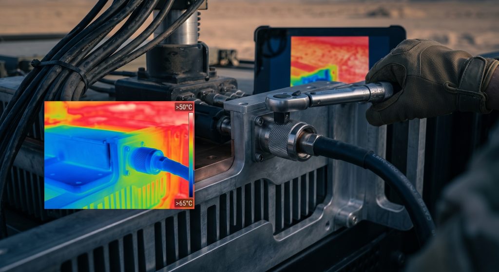
The physical act of integrating the hardware into the vehicle often introduces the very structural failures the defense system is designed to prevent. Technicians utilizing standard mechanics’ hand tools rather than calibrated RF torque wrenches routinely overtighten physical connectors. Applying excessive mechanical torque crushes the outer conductor and severely deforms the PTFE dielectric material inside the junction. This physical deformation permanently alters the concentricity of the coaxial structure, causing localized impedance shifts and severe signal return loss. Conversely, under-tightening the connectors guarantees that the harsh environmental vibrations of the C-UAS Countermeasure Vehicle will rattle the interface loose entirely, leading to intermittent signal transmission and massive power reflections. Furthermore, bending stiff coaxial cables beyond their specified minimum bend radius creates internal micro-fractures in the copper shielding and alters the strict distance between the center pin and the outer shield. These micro-fractures remain invisible beneath the outer polyurethane jacket but present a catastrophic physical barrier to the 5.8 GHz signal, completely neutralizing the effectiveness of the counter-drone capability.
How Do Environmental Stressors Degrade Output Power?
The final variable in the physical vehicle deployment involves the persistent ingress of environmental contaminants. Dust, particulate matter, and moisture dramatically alter the delicate dielectric properties of any exposed RF interface. When a C-UAS Countermeasure Vehicle operates in high-humidity or tropical environments, condensation physically forms inside microscopic voids within the exterior antenna feed lines. Liquid water possesses a very high dielectric constant. The presence of moisture within the main transmission line completely disrupts the strict 50-ohm impedance, absorbing microwave energy and converting it into localized steam. This thermal process rapidly destroys the connector from the inside out. The CRF-PA-5700M5900M-100W features hermetically sealed RF transitions and heavily machined chassis designs to repel these exact environmental stressors. However, the external cable harness remains highly vulnerable. Integrators must apply industrial-grade weatherproofing tapes and cold-shrink tubing to all external junctions. Ignoring this physical reality guarantees that environmental degradation will steadily consume the RF output power, slowly blinding the defensive systems over a matter of weeks.
| Environmental Factor | Physical Impact on System | Defense Strategy / Mitigation |
| High Humidity / Rain | Water ingress altering dielectric | Cold-shrink tubing, IP67 sealed connectors |
| Desert Dust / Sand | Contaminating connector mating surfaces | Dust caps during transport, sealed mating |
| Salt Fog (Coastal) | Accelerated galvanic corrosion | Nickel/Gold plating, anti-corrosion gels |
| Thermal Shock | Material expansion mismatch | RO4350B PCB, CTE-matched housing materials |
| Extreme Vibration | Fretting corrosion, loosening joints | Calibrated torque wrenches, lock-wire holes |
Conclusion
Successful Vehicle-Mounted Countermeasure System Integration demands strict adherence to microwave physics and materials science. The physical layer remains the most vulnerable segment of any C-UAS Countermeasure Vehicle, where insertion loss, thermal expansion, and vibration routinely destroy standard commercial hardware. Ignoring the mechanical reality of RF connections leads directly to burned transistors and compromised defense perimeters. CorelixRF engineers the CRF-PA-5700M5900M-100W to withstand these exact failures through internal isolation, ruggedized metallurgy, and strict impedance control. We invite system integrators, R&D directors, and procurement engineers to review our empirical laboratory data. Contact the CorelixRF engineering team today to request the official Data Sheet and discuss the physical integration requirements for your next high-power mobile deployment.
FAQ
Q1: What is the maximum acceptable insertion loss for a cable run connected to the CRF-PA-5700M5900M-100W?
We recommend designing the physical cable routing to maintain an insertion loss of no more than 3.0 dB from the amplifier output port to the antenna feed point. Losses exceeding this threshold require excessive thermal dissipation management within the vehicle rack to maintain effective radiated power.
Q2: Does the CRF-PA-5700M5900M-100W require external forced air cooling within the vehicle chassis?
Yes. While the module utilizes a high-mass aluminum chassis and copper baseplate for superior thermal conductivity, generating 100 watts of continuous wave RF power requires active thermal management. Integrators must provide adequate airflow across the heat sink fins to keep the baseplate temperature below 85°C.
Q3: Can we substitute standard SMA connectors for N-type connectors on the high-power output?
No. Standard SMA connectors lack the physical size and power-handling capability required for 100 watts of continuous wave power at 5.8 GHz. The physical junction will overheat, causing the PTFE dielectric to melt and creating a catastrophic short circuit. N-type or 4.3-10 connectors are mandatory for the primary output.
Q4: How does CorelixRF test the VSWR tolerance of the amplifier module?
Our laboratory engineers test the isolator circuitry by intentionally applying an infinite VSWR (an open circuit and a short circuit) directly to the output port while the amplifier operates at full saturation. We monitor the internal dummy load temperature and the GaN transistor junction temperatures to ensure zero degradation.
Q5: What tool is required to secure the RF connections on the C-UAS Countermeasure Vehicle?
Technicians must use a calibrated RF torque wrench specifically matched to the connector type (e.g., 12 in-lbs for specific N-type variants, per the manufacturer’s data). Standard wrenches cause irreversible physical damage to the internal geometry of the transmission line.
Authorized RF engineering and compliance review
For regulated RF systems, this page should be used as an engineering and compliance review path, not as a public deployment checklist. CorelixRF starts with authorization status, operating region, frequency plan, output limit, antenna interface, safety controls, thermal limits and acceptance documents.
- RFQ checklist – send the data buyers usually forget, including band, power, duty cycle, interface and test standard
- delivery documentation – check what documents can support incoming inspection, FAT review and long-term maintenance
- quality and certification review – review the quality and compliance evidence before the project moves into procurement
- RF front-end platform – compare the RF chain as a system instead of selecting one isolated module
- RF configurator – turn frequency, power, thermal and interface requirements into a first configuration brief
- case studies – review similar engineering paths before sending an RFQ
- engineering contact – send the application notes, block diagram or target specification to engineering sales
This keeps the discussion inside lawful, authorized RF programs while still giving procurement teams a clear way to request amplifier, antenna, SDR source, documentation and factory review.
Vehicle-Mounted RF Integration Review Path
For authorized vehicle-mounted RF integration, review RF front-end platform planning together with rugged RF amplifier options and antenna/load interface constraints. Share frequency bands, output power, vibration/thermal limits, DC power, control interface and acceptance evidence through the RF inquiry form.