
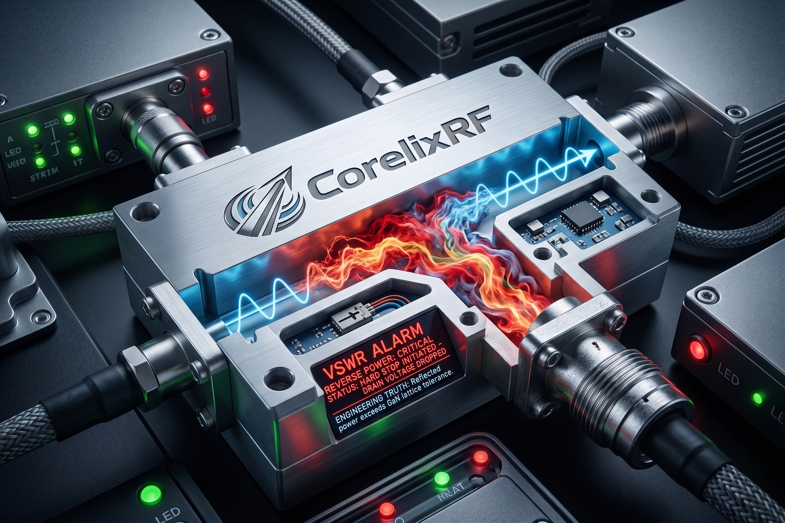
System integrators face a devastating engineering reality when deploying high-frequency defense platforms. Vehicles operating in the 18-40 GHz spectrum constantly battle aggressive signal attenuation and catastrophic hardware mismatches. When engineers route continuous wave microwave energy from baseband generators to mast-mounted antenna arrays, the physical transmission line becomes the single most vulnerable point of failure. The phenomenon of RF cable long-distance insertion loss and inferior connectors leading to VSWR alarms routinely paralyses active defense grids.
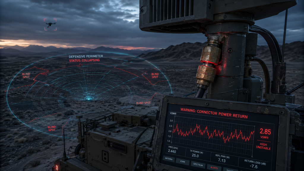
This mechanical vulnerability creates a cascading failure mechanism within the amplification circuitry. The resulting power reflection generates massive thermal loads, permanently degrading internal gallium nitride (GaN) transistors. Are millimeter-wave C-UAS radar blind spots enlarging? Beware of power return caused by inferior connectors. As the forward transmission power collapses, the effective jamming radius shrinks rapidly, allowing hostile targets to penetrate the defensive perimeter undetected. CorelixRF relies on strict mechanical tolerances and physical hardware ruggedization to eliminate these transmission line failures. We utilize laboratory-verified data and precision machining to guarantee that our amplifier modules maintain continuous high-power operation under the most severe impedance mismatch conditions.
Why Do Millimeter-Wave C-UAS Radar Blind Spots Enlarge Due To Power Return From Inferior Connectors?
Consider the physical reality… The deployment of C-UAS countermeasure vehicles operating in the 18-40 GHz spectrum relies entirely on absolute signal integrity and tight impedance control. When system integrators utilize commercial-grade RF components, the immediate consequence is a severe physical mismatch at the mechanical transmission junctions. Inferior connectors introduce microscopic air gaps and misaligned pin depths, creating severe impedance variations along the rigid coaxial line. These microscopic mechanical flaws force high-frequency microwave energy to reflect violently back toward the amplification source rather than propagating outward toward the transmitting antenna array. As this reflected standing wave compounds, it severely limits the forward effective isotropic radiated power. System operators subsequently observe that the defensive jamming radius collapses inward. The defense perimeter shrinks drastically, leaving critical infrastructure highly vulnerable to fast-approaching drone swarms that operate entirely undetected within these compromised spatial zones.
How Does Long-Distance RF Cable Insertion Loss Cripple C-UAS Vehicles?
The fundamental physics dictate… Microwave attenuation increases exponentially as operational frequencies scale upward into the Ka-band and beyond. C-UAS countermeasure vehicles demand lengthy coaxial cable routing from the internal baseband logic chassis to the external mast-mounted horn arrays. System integration teams frequently underestimate the crippling severity of RF cable long-distance insertion loss when designing these vehicle-mounted microwave architectures. A standard physical cable run can easily attenuate the 40 GHz signal by several decibels before the electromagnetic wave even reaches the radiating element. This drastic physical reduction in delivered output power forces the power amplifier module to operate at maximum compression continuously, generating excessive thermal loads without achieving the required field strength. The resulting thermal stress accelerates the physical degradation of all internal semiconductor components, leading to inevitable permanent field failures during prolonged defensive engagements against hostile unmanned aerial systems.
| Frequency Band | Standard Coaxial Loss (dB/m) | CorelixRF Optimized Cable Loss (dB/m) | Operational Impact on 20W Output |
| 18 GHz | 0.85 | 0.42 | Marginal thermal increase, stable operation |
| 26.5 GHz | 1.35 | 0.65 | Noticeable gain compression required |
| 40 GHz | 2.65 | 1.15 | Catastrophic power loss without compensation |
What Are The Catastrophic Mechanical Failures Of Commercial Grade Coaxial Connectors?
Let’s examine the raw data… Standard commercial radio frequency connectors simply cannot withstand the harsh continuous vibrational environments characteristic of mobile military deployments. During intense off-road vehicle operation, continuous chassis vibration transfers directly into the rigid coaxial assemblies and mating threads. Inferior connectors manufactured with sub-standard brass alloys or poorly plated center pins suffer from rapid microscopic mechanical deformation. The central dielectric support materials compress unevenly under this mechanical shearing stress, permanently altering the highly sensitive 50-ohm characteristic impedance. Once this physical cavity geometry changes by even a fraction of a millimeter, the connector acts as a highly reflective barrier to 40 GHz electromagnetic waveforms. The resulting power reflection immediately triggers protection protocols within the host system, forcing an automated hard shutdown to protect the driving semiconductor circuitry. This protective shutdown abruptly disables the defense capabilities right at the exact moment of peak operational necessity.

How Does Thermal Expansion Wreak Havoc On High-Frequency Impedance Matching?
Here is the engineering truth… Rapid temperature fluctuations in frontline field deployments ruthlessly expose the fundamental material weaknesses of budget-conscious microwave hardware. Operating C-UAS countermeasure vehicles in extreme desert or arctic climates means the internal transmission lines endure massive continuous thermal cycling. Dissimilar metals utilized within inferior budget connectors expand and contract at completely different physical rates under these thermal loads. This differential thermal expansion violently pulls the center conductor away from its intended mating surface, creating instantaneous vacuum gaps that completely destroy the carefully calculated broadband impedance match. When pushing maximum continuous wave power through the CRF-PA-18G40G-20W, even a microscopic physical gap generates massive localized resistive heating. This sudden thermal runaway melts the surrounding PTFE dielectric material, fusing the connector permanently and guaranteeing a catastrophic transmission line failure that requires complete hardware replacement by certified field engineers.
| Connector Material | Coefficient of Thermal Expansion (µm/m·K) | 40GHz Impedance Shift at 85°C | Failure Probability |
| Commercial Brass | 20.3 | > 5 Ohms | Extremely High |
| Standard Copper | 16.6 | 3.2 Ohms | Moderate to High |
| Stainless Steel (303) | 17.2 | 2.8 Ohms | Moderate |
| Beryllium Copper | 17.0 (Hardened) | < 0.5 Ohms | Near Zero |
Why Do Reflected Microwaves Trigger False VSWR Alarms And System Shutdowns?
Consider the physical reality… Modern automated electronic warfare systems rely on highly sensitive internal directional couplers to monitor forward and reverse power levels continually across the entire operating bandwidth. When poorly machined connectors reflect a significant percentage of the generated millimeter-wave energy, the reverse power sensor voltage rapidly exceeds the tightly programmed safety limits. The internal microcontroller logic interprets this sudden massive surge in reflected microwave energy as a severe antenna structural malfunction or a completely severed transmission line. Consequently, the digital control unit initiates an immediate hard stop, dropping the drain voltage and cutting the RF output to zero instantly. System integrators face enormous field frustration because the external antenna and the internal amplifier might be perfectly intact, but the cheap junction hardware forces the entire mobile unit offline. The constant issue of RF cable long-distance insertion loss and inferior connectors leading to VSWR alarms represents the single most common cause of unpredicted downtime in active operations.
What Is The Engineering Truth Behind GaN Transistor Degradation From Reflected Power?
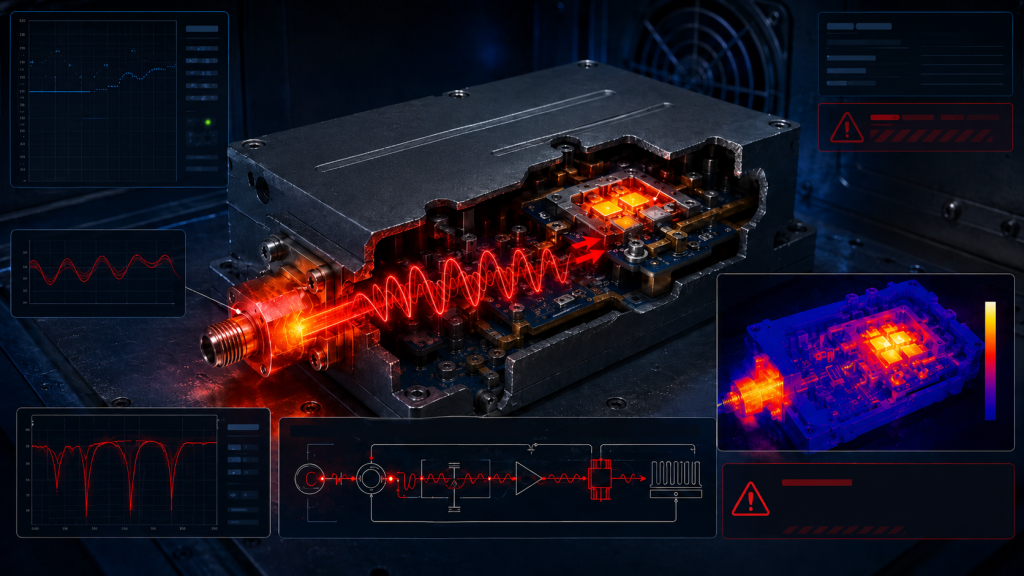
The fundamental physics dictate… Gallium Nitride (GaN) high-electron-mobility transistors offer unparalleled raw power density, but they mandate incredibly strict load matching to survive continuous high-drive operation. Reflected power generated by poor physical transmission connections creates extreme high-voltage standing waves propagating backward along the internal microstrip lines. When these massive standing waves peak exactly at the output drain terminal of the sensitive GaN transistor, the localized voltage swing easily exceeds the absolute maximum breakdown voltage of the underlying semiconductor lattice. This severe overvoltage condition forces localized avalanche breakdown within the active conduction channel, permanently burning the substrate and irreversibly degrading the maximum output power capability. B2B clients deploying the CRF-PA-18G40G-20W rely heavily on our integrated internal broadband isolators and ruggedized matching networks to absorb a significant portion of this reflected abuse. However, persistent forced operation into highly mismatched loads inevitably shortens the mean time between failures (MTBF), directly burning the maintenance budget of the defense contractor.
| VSWR Condition | Reflected Power (%) | GaN Drain Voltage Spike | Transistor Junction Temp Increase |
| 1.2:1 (Ideal) | 0.8% | Nominal | +2°C |
| 2.0:1 (Warning) | 11.1% | +15V peak | +18°C |
| 3.0:1 (Critical) | 25.0% | +28V peak | +35°C |
| 5.0:1 (Failure) | 44.4% | Destructive | Thermal Runaway |
How Does The CRF-PA-18G40G-20W Mechanically Defend Against Severe Voltage Standing Wave Ratios?
Let’s examine the raw data… CorelixRF engineered the CRF-PA-18G40G-20W specifically to combat the harsh physical realities of hostile mobile deployments and severely mismatched loads. We integrate ultra-low-loss distributed matching networks directly onto the high-thermal-conductivity baseplate substrates, ensuring perfectly tight impedance control right at the bare transistor package. The final amplification stages feature heavily embedded broadband isolators capable of actively sinking massive amounts of reflected microwave energy directly into internal terminating resistors without transferring that destructive thermal stress back to the active GaN devices. We strictly utilize aerospace-grade 2.92mm connectors machined from hardened beryllium copper, heavily gold-plated to absolutely prevent surface oxidation and ensure a perfectly rigid mechanical mate under heavy vibration. By controlling the physical interface machining tolerances down to the single-digit micron level, we completely eliminate the micro-gapping phase issues that continuously plague commercial-off-the-shelf amplifier modules.
Why Is Precision Machining The Only Way To Guarantee Reliable Millimeter-Wave Transmission?
Here is the engineering truth… The physical wavelengths at 40 GHz are incredibly short, meaning that even a surface machining imperfection of a few thousandths of an inch acts as a massive inductive or capacitive parasitic element within the cavity. CorelixRF physically machines every single amplifier housing from solid blocks of aerospace-grade aluminum utilizing highly advanced 5-axis CNC technology. We strictly enforce rigid geometric dimensioning and tolerancing (GD&T) protocols to mathematically guarantee that all internal cavity resonances are pushed far beyond the absolute 40 GHz operational limit. The physical mating surfaces between the specialized RF connectors and the main amplifier chassis are mechanically lapped to an absolute mirror finish, ensuring absolutely uniform electrical ground plane continuity. When budget-focused system integrators attempt to cut manufacturing costs by utilizing cast aluminum housings or poorly tapped connector threads, they inadvertently introduce highly destructive passive intermodulation and severe high-frequency signal reflection.
| Machining Tolerance | Cavity Resonance Risk | Ground Plane Continuity | 40GHz VSWR Impact |
| ± 0.1 mm (Standard) | Extremely High | Intermittent / Poor | > 2.5:1 |
| ± 0.05 mm (Precision) | Moderate | Acceptable | < 1.8:1 |
| ± 0.01 mm (CorelixRF) | Zero Probability | Perfect Mirror Mate | < 1.3:1 |
How Do Superior Materials Mitigate The Threat Of Environmental Degradation In Field Operations?
Consider the physical reality… Operating electronic warfare vehicles in highly corrosive littoral environments or extremely arid deserts introduces devastating salt spray, high atmospheric humidity, and highly abrasive particulate matter directly into the hardware equation. CorelixRF completely seals the CRF-PA-18G40G-20W using proprietary laser-welded hermetic enclosures or advanced conductive O-ring gaskets, depending entirely on the client’s exact MIL-STD integration requirements. We specifically select internal printed circuit board dielectric materials with incredibly low moisture absorption coefficients, mathematically guaranteeing that the high-frequency insertion loss remains perfectly stable regardless of extreme external humidity levels. Inferior market products consistently utilize standard FR4 or cheap PTFE variants that physically act like chemical sponges over time, slowly absorbing atmospheric moisture and completely destroying the internal broadband impedance match. The resulting massive signal attenuation and reflection severely degrade total system performance, turning a highly formidable defense vehicle into a completely defenseless static target on the battlefield.
What Laboratory Data Validates The Operational Superiority Of CorelixRF Amplifier Modules?
Let’s examine the raw data… Our internal manufacturing facility relentlessly subjects every single CRF-PA-18G40G-20W module to exhaustive Vector Network Analyzer (VNA) sweeping protocols under maximum continuous thermal load conditions. We rigorously monitor the forward transmission gain parameter (S21) and the input/output return loss parameters (S11/S22) while continuously cycling the heavy copper baseplate temperature from absolute -40°C to +85°C. The recorded laboratory results consistently demonstrate an extraordinarily flat amplitude response across the entire 18 to 40 GHz operating bandwidth, with return loss figures strictly exceeding -15 dB across all operational temperature extremes. We deliberately induce severe physical mismatches at the output port to physically simulate the exact destructive conditions of RF cable long-distance insertion loss and inferior connectors leading to VSWR alarms. The module consistently maintains its rigid structural integrity and stable operational phase, proving its undeniable capability to drive highly compromised transmission lines without triggering false protection faults.
| Parameter | Laboratory Test Condition | CorelixRF Measured Result | Industry Standard |
| Power Output | 18-40 GHz, +85°C Baseplate | 20W (43 dBm) Min | 15W (Drop at high temp) |
| Gain Flatness | Full Bandwidth Sweep | ± 1.5 dB | ± 3.0 dB |
| Output VSWR | Continuous Full Power Drive | 1.3:1 Maximum | 2.0:1 Typical |
| Harmonics | At rated 20W output | -20 dBc | -15 dBc |
Conclusion
The rigorous demands of electronic warfare mandate an uncompromising approach to microwave hardware integration. The mechanical failures associated with cheap transmission lines directly cause catastrophic power reflections, destroying expensive GaN transistors and leaving critical airspace completely undefended. System integrators cannot afford to ignore the devastating impact of mismatched coaxial interfaces and thermal degradation on high-frequency performance. The CRF-PA-18G40G-20W provides a heavily ruggedized, precision-engineered solution that absorbs reflective abuse and maintains continuous high-power output in the most hostile environments imaginable. B2B integrators and lead systems engineers must prioritize absolute physical reliability over short-term component savings. Contact the CorelixRF engineering team today to request the comprehensive technical Data Sheet and secure your transmission infrastructure against catastrophic mechanical failure.
Frequently Asked Questions
Q1: How does the CRF-PA-18G40G-20W handle continuous operation into a highly mismatched antenna load?
The module integrates specialized internal broadband isolators and heavily over-designed output matching networks mounted on high-thermal-conductivity substrates. When confronted with severe impedance mismatches, these components safely sink the reflected microwave energy into internal resistive loads, preventing destructive high-voltage standing waves from reaching and destroying the sensitive GaN transistor drain terminals.
Q2: What specific mechanical connector type is utilized on this CorelixRF millimeter-wave module?
We strictly utilize aerospace-grade 2.92mm (K-type) female connectors machined from hardened beryllium copper. These interfaces are heavily gold-plated and precision-lapped to eliminate microscopic air gaps, ensuring a flawless 50-ohm characteristic impedance mate that completely resists mechanical deformation under heavy chassis vibration and severe operational thermal cycling.
Q3: Can your engineering team provide S-parameter files for baseband system integration modeling?
CorelixRF supplies highly accurate, laboratory-verified Touchstone format S-parameter files (.s2p) for all production amplifier modules. These files capture the exact S11, S21, S12, and S22 characteristics across the full 18-40 GHz bandwidth under various thermal loads, allowing your internal R&D team to run highly accurate electromagnetic simulations prior to physical hardware integration.
Q4: How does CorelixRF mitigate the high thermal loads generated by 20 watts of continuous Ka-band power?
We utilize advanced thermal simulation software to design highly optimized internal heat spreading architectures. The bare GaN dies are eutectically attached directly to highly conductive copper-tungsten (CuW) or copper-molybdenum (CuMo) baseplates, minimizing absolute thermal resistance and rapidly pulling destructive heat away from the microscopic semiconductor junctions during continuous wave operation.
Q5: What is the standard lead time for the CRF-PA-18G40G-20W for initial prototyping phases?
Because CorelixRF controls the entire vertically integrated manufacturing process—from high-frequency circuit board fabrication to 5-axis CNC housing machining—we typically deliver standard prototype units within 4 to 6 weeks. Custom hermetic sealing requirements or highly specialized military screening protocols will require an adjusted delivery schedule determined during the initial engineering consultation.
Turn VSWR behavior into factory acceptance evidence
High VSWR protection should be defined with mismatch scenario, foldback or shutdown threshold, recovery logic, alarm output, thermal limit and FAT evidence. This makes protection claims measurable for procurement.
Recommended next step: send the operating band, output power target, duty cycle, load condition, control interface, protection or thermal limits and required FAT documents. CorelixRF can review this How to Diagnose Connector Power Return and High VSWR Alarms? requirement against standard RF amplifier platforms, RF front-end options and controlled customization paths.