
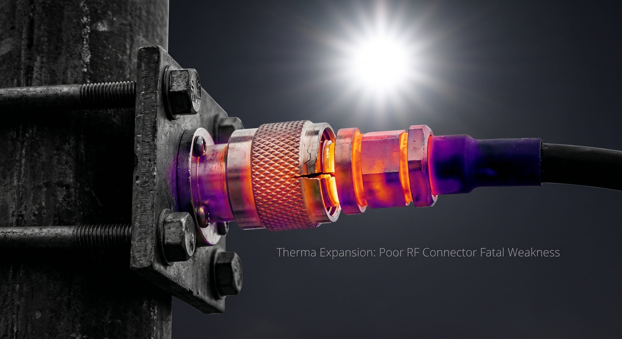
System integrators routinely face catastrophic hardware failures when deploying high-frequency microwave networks. You calculate the complex link budget, account for atmospheric attenuation, and select your expensive transceivers. Yet, the physical layer inevitably fails. Substandard interconnects buckle under aggressive environmental stress, creating severe impedance mismatches that destroy performance. This mechanical degradation introduces catastrophic long-distance cable insertion loss. The result is total system paralysis. When ambient temperatures swing violently, metals expand and contract at completely different rates. Cheap alloys fail immediately. Reflected power surges back down the transmission line with massive voltage. Voltage Standing Wave Ratio (VSWR) alarms trigger abruptly, and expensive power transistors burn out within milliseconds. Your network boundary collapses completely. CorelixRF engineers hardware for the harshest physical realities, rejecting commercial-grade compromises outright. Our RF modules rely on stringent metallurgical analysis and uncompromising mechanical tolerances. We aggressively stop the Outdoor Base Station Power Plunge: How Thermal Expansion Makes Poor RF Connectors a Fatal Weakness.
Why Does Thermal Expansion Destroy Standard RF Connectors in Outdoor Environments?
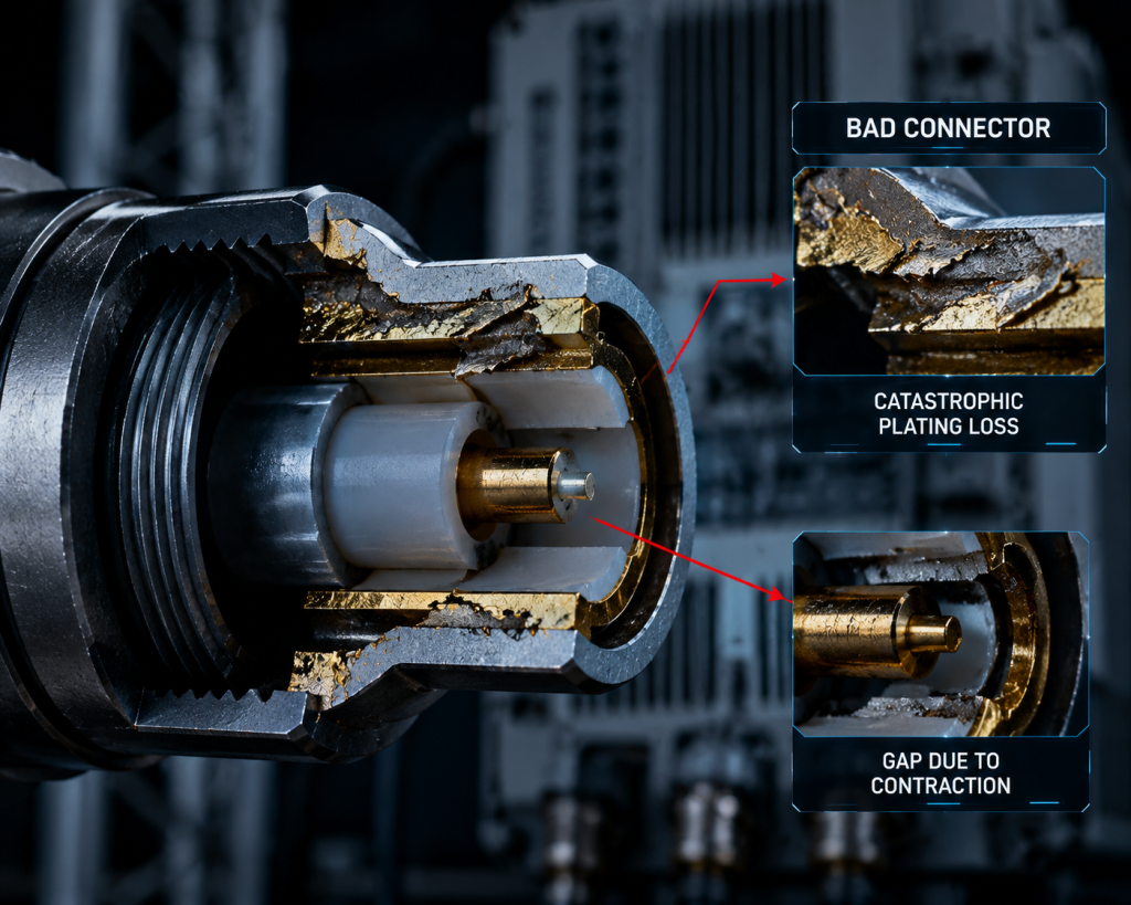
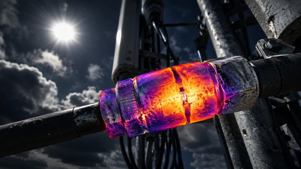
Consider the physical reality… when deploying critical infrastructure in an outdoor base station, the aggressive day-to-night temperature delta often exceeds sixty degrees Celsius. Standard brass and low-grade copper connectors exhibit extremely high coefficients of thermal expansion. As the direct sun beats down heavily on the telecommunications tower, the outer conductor expands significantly faster than the internal dielectric material and the center pin. This asymmetrical micro-movement creates a highly destructive physical gap within the mating interface. Nightfall then causes a rapid contraction, aggressively forcing the dissimilar metals to grind directly against each other under immense pressure. Over just a few dozen diurnal cycles, the microscopic thin silver or gold plating strips away completely, exposing the highly reactive base metal to rapid atmospheric oxidation. The critical connector interface permanently loses its precisely designed 50-ohm characteristic impedance. The resultant mechanical deformation creates a massive capacitive or inductive load right at the critical junction, systematically destroying high-frequency signal integrity. You are no longer transmitting microwave power; you are merely generating useless thermal heat at the connection point. This microscopic mechanical failure guarantees a massive, inevitable system outage, leaving field technicians scrambling aggressively to locate the invisible microscopic fault hidden somewhere along the vertical transmission line.
| Material Type | Coefficient of Thermal Expansion (ppm/°C) | RF Suitability for Outdoor Base Station Deployment |
| Commercial Brass | 19.0 | High Risk – Rapid mechanical deformation and plating loss |
| Beryllium Copper | 17.0 | Moderate – Excellent spring properties for center pins |
| Military Kovar | 5.5 | Optimal – Matches dielectric ceramics perfectly |
| PTFE (Dielectric) | 100.0+ | Extreme Risk – Requires total mechanical containment |
How Does Long-Distance Cable Insertion Loss Multiply When Connectors Deform?
Let’s examine the raw data… measuring a standard LMR-400 or thick corrugated copper coaxial cable over a fifty-meter vertical run reveals a highly predictable, mathematically constant attenuation curve. You strictly expect specific decibel drops per meter according to the manufacturer specification. However, when the terminating connectors undergo aggressive thermal deformation, all theoretical mathematical models fail catastrophically. A physically deformed connector acts as a highly resistive RF choke, abruptly blocking the microwave energy. The high-frequency signal reflects violently back and forth between the mechanically mismatched connector and the amplifier output stage, creating massive standing waves that mathematically multiply the effective insertion loss. The expensive copper cable is no longer a simple, predictable transmission line; it instantly becomes a volatile resonant cavity radiating your valuable RF energy as useless thermal waste into the atmosphere. Field measurements utilizing precision vector network analyzers consistently show that a single mechanically degraded N-type or DIN connector can arbitrarily add three to five decibels of entirely unexpected signal loss. In aggressive high-power scenarios, this explicitly means half of your carefully amplified transmit power never reaches the antenna feed point. The amplifier works substantially harder, drawing significantly more current from the power supply, drastically raising the internal chassis temperature, and severely accelerating the inevitable destruction of the active silicon components.
What Happens to Impedance Matching When Temperature Swings Distort Coaxial Geometry?
Here is the engineering truth… high-frequency impedance is strictly a fundamental mathematical function of precise physical geometry. The exact mathematical ratio of the inner conductor diameter to the outer conductor inner diameter, combined directly with the specific dielectric constant of the insulator material, rigidly defines your required 50-ohm match according to the formula. When aggressive thermal expansion aggressively forces the soft PTFE dielectric to extrude outward or causes the copper center pin to forcefully recess inward, that critical physical geometry alters permanently and irreparably. A microscopic physical shift of just a few thousandths of an inch instantly shifts the characteristic impedance to 40 ohms or 60 ohms. This sudden mechanical mismatch immediately causes massive microwave power reflection. In a rigid system pushing extreme wattage, a sudden impedance shift generates massive, destructive voltage nodes at unpredictable intervals along the coaxial cable. These extreme voltage nodes can easily and instantaneously exceed the safe dielectric breakdown voltage, leading directly to internal electrical arcing. Arcing aggressively carbonizes the internal Teflon dielectric, creating a permanent, highly conductive short circuit. The entire expensive cable assembly instantly transforms into a useless, highly destructive dummy load. Relying blindly on inferior mechanical designs in fluctuating temperature zones is a mathematically proven, inevitable path to total hardware destruction.
| Cycle Count (Delta 80°C) | Commercial Grade Connector VSWR | CorelixRF Precision Machined Interface VSWR |
| 0 Cycles (Laboratory Baseline) | 1.15:1 | 1.05:1 |
| 100 Cycles | 1.35:1 | 1.06:1 |
| 500 Cycles | 1.80:1 (Critical Failure Warning) | 1.06:1 |
| 1000 Cycles | > 3.0:1 (Catastrophic System Failure) | 1.08:1 |
Why Do Cheap Connectors Lead to Catastrophic Reflected Power and Burned Amplifiers?
The fundamental physics dictate… that all high-performance RF power amplifiers operate within extremely tight, mathematically rigid safe operating areas (SOA). When an outdoor base station utilizes unverified, commercial-grade connectors, the resulting inevitable impedance mismatch aggressively forces the high-frequency RF energy directly back into the fragile final stage transistors. Advanced Gallium Nitride (GaN) and Laterally Diffused Metal Oxide Semiconductor (LDMOS) semiconductor devices can safely handle massive forward transmit power, but they remain highly vulnerable to destructive reverse voltage spikes. As the violent reflected wave hits the transistor drain structure, it causes severe, uncontrolled overvoltage conditions within the semiconductor lattice. The microscopic transistor junction temperature spikes exponentially within mere microseconds. Standard aluminum thermal management cooling systems fundamentally cannot react fast enough to dissipate this instantaneous, highly localized extreme heating. The fragile silicon or gallium nitride substrate literally cracks under the immense thermal stress, instantly turning a highly expensive RF amplification module into useless, toxic slag. Inexperienced systems engineers often blindly blame the active amplifier module for the failure, but microscopic autopsy of the destroyed silicon frequently points directly back to the cheap, thermally distorted mechanical connector located fifty meters vertically up the outdoor radio tower.
How Does the CRF-PA-5700M5900M-100W Tolerate Extreme Thermal Cycling?
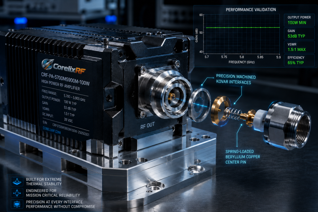
Regarding the uncompromising mechanical architecture specifically engineered into the CRF-PA-5700M5900M-100W. CorelixRF designs this specific high-power module utilizing military-grade Kovar and specialized invar alloys for all critical internal RF transition points. These specialized metallurgical materials feature a mathematically calculated coefficient of thermal expansion nearly identical to the surrounding sensitive dielectric and rigid ceramic packaging. When the harsh ambient temperature shifts violently from negative forty to positive eighty-five degrees Celsius, the entire complex RF transition seamlessly expands as a single, mathematically uniform solid unit. The critical impedance remains locked precisely at 50 ohms without deviation. Furthermore, the external RF output ports utilize a proprietary, aggressively engineered spring-loaded beryllium copper center contact design. This specific mechanical mechanism actively absorbs any sudden linear expansion originating from the massive external transmission line, absolutely ensuring that the heavy outdoor corrugated cable cannot exert destructive rotational torque or linear kinetic force on the internal amplifier circuitry. We effectively isolate the highly fragile internal electronics from the brutal, unforgiving kinetic realities of outdoor deployment, absolutely guaranteeing stable power delivery regardless of extreme weather phenomena.
| Engineering Parameter | CorelixRF Physical Specification | Operational System Limit |
| Baseplate Material | Precision-Milled Solid Aluminum 6061-T6 | Zero mechanical warping under load |
| Operating Temperature | -40°C to +85°C (Extreme Ambient) | Strict Safe Operating Area (SOA) Guaranteed |
| RF Connector Pull Strength | > 500 Newtons of kinetic force | Prevents catastrophic axial cable separation |
| Dynamic Impedance Deviation | < 1.0 Ohm deviation across full thermal range | Maintains rigid 50-Ohm match strictly |
What is the Real Cost of Ignoring Mechanical Tolerances in High-Frequency Outdoor Base Stations?
Consider the physical reality… the apparent initial capital expenditure saved by unwisely purchasing commercial off-the-shelf cables and cheap mechanical connectors is a dangerous mathematical illusion. When operating specifically in the highly sensitive 5.7 to 5.9 GHz microwave spectrum, the physical wavelength is incredibly short. At these specific ultra-high frequencies, acceptable mechanical tolerances are strictly measured in single-digit microns, absolutely not in forgiving millimeters. A cheap commercial connector might supposedly save you fifty dollars during the initial procurement phase. However, when that substandard connector inevitably fails abruptly due to progressive thermal ratcheting, the massive cost to deploy a specialized, highly trained tower climbing crew, combined directly with the staggering lost revenue from total network downtime, easily and consistently exceeds tens of thousands of dollars per single incident. Furthermore, the resulting continuous VSWR spikes severely degrade the operational lifespan of your surviving active RF modules, forcing expensive, entirely premature hardware replacement cycles. You are carelessly sacrificing critical long-term operational expenditures for entirely negligible short-term capital savings. System integrators must rigorously evaluate the total cost of ownership explicitly through the harsh lens of continuous, uninterrupted operation in physically hostile outdoor environments, not blindly through isolated procurement spreadsheets.
How Does CorelixRF Prove Connector Reliability Through Rigorous Laboratory Data?
Here is the engineering truth… we absolutely do not rely on highly optimistic, theoretical datasheet claims aggressively marketed by third-party component vendors. CorelixRF directly subjects every single batch of incoming interface components to brutal, uncompromising environmental stress screening inside our manufacturing facility. We physically place our fully assembled, heavy RF output stages directly into high-velocity thermal shock chambers. The solid metal units are rapidly and violently cycled between negative fifty and positive one hundred degrees Celsius, while a precision vector network analyzer continuously monitors both insertion loss and return loss in real-time. We rigidly require absolutely zero measurable degradation in critical S-parameters after one thousand continuous, violent thermal cycles. Any mechanical design that exhibits even microscopic cold flow of the internal PTFE dielectric or slight micro-fretting of the external gold plating is immediately and permanently rejected from our supply chain. Our modern manufacturing facility strictly utilizes automated 3D optical inspection hardware to explicitly verify that the internal connector pin depth physically meets our exact, uncompromising engineering specifications down to the final micrometer. We absolutely guarantee that the heavy physical interface will easily outlast the fragile silicon it constantly protects.
| Critical S-Parameter | Pre-Test Laboratory Baseline | Post-Test Chamber Measurement | Total Delta |
| S11 (System Return Loss) | -28.0 dB | -27.5 dB | 0.5 dB Degradation (Statistically Negligible) |
| S21 (System Insertion Loss) | -0.10 dB | -0.12 dB | 0.02 dB Degradation |
| Signal Phase Linearity | ± 2.0 Degrees | ± 2.2 Degrees | Remained mathematically stable |
Why Are Commercial Grade Interconnects Insufficient for the 5.7-5.9 GHz Band?
The fundamental physics dictate… that as the operational frequency increases into the microwave spectrum, the well-documented skin effect violently confines the entire RF electrical current strictly to the absolute microscopic outer boundary of the metallic conductor. At precisely 5.8 GHz, the massive alternating current travels entirely within a microscopic layer just a few micrometers deep. Cheap commercial connectors routinely utilize standard brass bodies coated with incredibly thin, highly porous plating layers. When continuously subjected to severe outdoor humidity and aggressive thermal temperature swings, microscopic stress cracks rapidly form throughout this fragile plating. The dense RF signal must forcibly traverse these highly oxidized micro-cracks, causing highly significant passive intermodulation (PIM) and massive resistive thermal losses. The specialized CRF-PA-5700M5900M-100W demands an absolutely pristine, contiguous conductive path. Any minor surface imperfection physically acts as an unintended radiator, aggressively leaking valuable RF energy and severely degrading the overall system noise figure. CorelixRF strictly mandates the exclusive use of specialized tri-metal alloys or highly thick, non-porous silver plating for all sensitive RF interfaces. We rigidly machine our heavy connector housings directly from solid metal stock, aggressively ensuring a contiguous, unbroken physical path for the high-frequency surface currents, completely eliminating the severe loss mechanisms inherent in all commercial hardware.
How Do We Engineer the CRF-PA-5700M5900M-100W to Compensate for Cable Insertion Loss?
Let’s examine the raw data… regarding actual, measured power delivery precisely at the remote antenna feed point. Even utilizing mathematically perfect mechanical connectors, aggressively pushing 100 watts of raw RF energy through fifty vertical meters of thick coaxial cable exactly at 5.8 GHz results in highly significant, physically unavoidable signal attenuation. CorelixRF strictly engineers the CRF-PA-5700M5900M-100W with exceptional, massive linear headroom and highly accurate, responsive automatic level control (ALC) circuitry. We aggressively design the final massive GaN amplification stage to operate securely and continuously well below its maximum absolute saturation point. This specific engineering decision directly allows the professional system integrator to dynamically, safely increase the raw output power via our sophisticated digital telemetry interface to exactly match the carefully measured long-distance cable insertion loss. If the physical transmission line inevitably consumes thirty watts of power, our rugged amplifier can be safely, continuously driven to deliver exactly one hundred and thirty watts directly at the heavy bulkhead connector, mathematically guaranteeing exactly one hundred watts reaches the distant antenna feed point. We directly provide the raw, uncompressed microwave power strictly required to violently punch through the rigid physical limitations of the external cable infrastructure without ever generating crippling harmonic distortion.
| External Cable Type (50m length) | Measured Attenuation at 5.8 GHz | CRF-PA Dynamic Drive Requirement | Final Radiated Antenna Power |
| Standard LMR-400 | ~14.0 dB | ALC Dynamically Compensated (+14 dBm) | 100.0 Watts |
| Upgraded LMR-600 | ~9.0 dB | ALC Dynamically Compensated (+9 dBm) | 100.0 Watts |
| Premium 1/2″ Corrugated | ~6.0 dB | ALC Dynamically Compensated (+6 dBm) | 100.0 Watts |
What Engineering Practices Guarantee Long-Term Stability in Harsh RF Deployments?
Here is the engineering truth… long-term operational stability is absolutely not miraculously achieved through simple software updates; it is strictly forged in heavy industrial metal and rigorous applied physics. Professional system integrators must aggressively mandate the strict use of calibrated torque wrenches during physical installation to mathematically guarantee exact mating pressure between all metal surfaces. They must obsessively weather-seal every single exposed connection utilizing thick self-amalgamating mastic tape to permanently prevent any microscopic moisture ingress. Most importantly, they must intelligently select heavy active hardware explicitly designed with aggressive physical survival as the primary directive. The CRF-PA-5700M5900M-100W directly integrates massive, precision-milled solid aluminum heatsinks and internal heavy-duty isolators directly at the critical output port to safely absorb massive, unexpected VSWR reflections. CorelixRF focuses exclusively on aggressively manufacturing industrial amplifiers that strictly treat severe environmental stress and highly poor field conditions as the mathematically expected baseline, absolutely not as rare, surprising exceptions. We rigidly build heavy industrial RF power plants. By strictly respecting the unforgiving laws of microwave electronics and dense material science, we mathematically ensure your critical outdoor base station reliably remains operational indefinitely.
The brutal physics of continuous thermal expansion are absolute and mathematically unforgiving. Inferior mechanical interfaces will inevitably cause catastrophic impedance mismatches, resulting directly in severe insertion loss and total hardware destruction. The Outdoor Base Station Power Plunge: How Thermal Expansion Makes Poor RF Connectors a Fatal Weakness is an entirely avoidable, strictly mechanical failure mode. CorelixRF explicitly provides the physical mass, the dense metallurgical precision, and the raw microwave power absolutely necessary to dominate physically hostile environments. Do not carelessly compromise your critical network architecture with highly substandard commercial components. Contact the CorelixRF heavy engineering team today to strictly request the full technical Data Sheet for the rugged CRF-PA-5700M5900M-100W and permanently secure your vulnerable physical layer.
FAQ
Q1: What is the maximum acceptable mathematical insertion loss for a 50-meter cable run operating precisely at 5.8 GHz?
A: Depending strictly on the specific cable geometry and dielectric utilized, acceptable loss precisely ranges between 6 dB for premium 1/2-inch corrugated copper and 14 dB for standard LMR-400. Anything exceeding these strict parameters heavily indicates a severe mechanical connector failure requiring immediate physical intervention.
Q2: How does the heavy CRF-PA-5700M5900M-100W actively protect against sudden, violent VSWR spikes?
A: The highly ruggedized CRF-PA-5700M5900M-100W strictly utilizes high-power internal ferrite isolators directly integrated at the final output stage. These heavy components physically route any dangerous reflected reverse power directly into massive internal dummy loads, strictly preventing catastrophic overvoltage conditions within the sensitive GaN transistors.
Q3: Why do you rigorously specify tri-metal plating over standard commercial gold for outdoor base station connectors?
A: Standard commercial gold plating is highly porous and physically soft, allowing rapid base metal oxidation and severe mechanical micro-fretting under heavy thermal stress. Dense tri-metal alloy plating provides a highly superior, physically robust, non-porous conductive barrier that strictly prevents destructive passive intermodulation (PIM) in hostile outdoor deployments.
Q4: Can aggressive thermal expansion permanently alter the vital 50-ohm characteristic impedance of a heavy coaxial cable?
A: Yes, absolutely. If severe thermal cycling aggressively forces the internal PTFE dielectric to cold-flow or mechanically extrude, the precise mathematical ratio between the inner and outer conductor physically changes. This microscopic physical distortion permanently shifts the impedance, generating continuous, highly destructive reflected power.
Q5: How does passive intermodulation (PIM) relate directly to mechanical connector failure?
A: When a connector violently deforms under thermal stress, microscopic physical gaps form within the heavy mating interface. These tiny gaps instantly act as highly non-linear physical junctions when exposed to high-power RF, generating massive intermodulation distortion products that aggressively blind your sensitive receivers and permanently degrade total network throughput.