
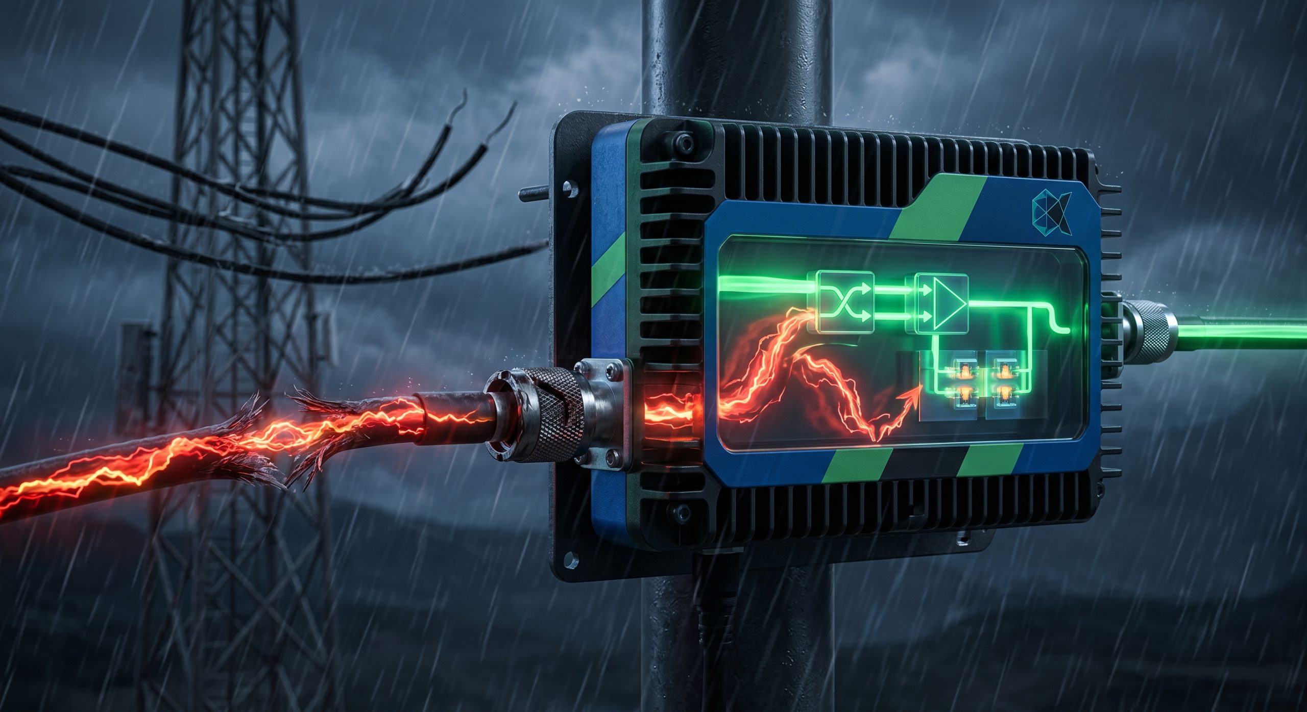
Outdoor base station deployment presents unforgiving physical environments that aggressively degrade transmission hardware. System integrators and engineers routinely battle severe impedance mismatches stemming from RF cable long-distance insertion loss and mechanical failure caused by inferior connectors. These variables generate aggressive signal reflections right at the amplification output stage, creating highly reactive loads that destabilize the entire communication node.
Connect VSWR protection needs to amplifier and RF front-end review
Strict VSWR protection should be evaluated with amplifier power class, antenna matching, shutdown logic, monitoring interface and acceptance data. CorelixRF can review the complete RF path before RFQ.
When a high-power radio frequency signal hits a mismatched boundary, the reflected electromagnetic energy returns directly into the amplification stages. The resulting voltage standing wave ratio (VSWR) peaks can instantaneously exceed the physical breakdown voltage of the final-stage semiconductor devices. This standing wave causes rapid thermal runaway, leading to catastrophic system failure, incinerated internal RF components, and ultimately, a compromised operational defense perimeter. Field replacement logistics incur massive operational expenditures and unacceptable network downtime.
CorelixRF implements uncompromising physical hardware defense mechanisms to mitigate these physical realities. Relying solely on raw nominal output numbers proves completely inadequate when harsh weather physically destroys cable geometry. We design amplifiers built around physical survival under massive reflection profiles.
Why Do Inferior Connectors Cause Instant Catastrophic Failure In Outdoor Base Stations?
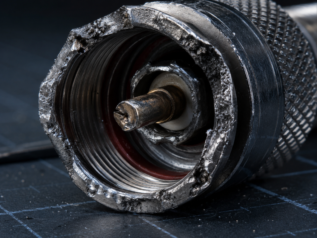
When selecting interconnects for high-frequency infrastructure. Low-grade RF connectors manufactured with inadequate machining tolerances introduce immediate impedance variations at the mating surfaces. Outdoor environments subject these connectors to relentless environmental stress. Inferior metal plating and sub-standard dielectric materials degrade rapidly under high-power transmission profiles. As the RF signal passes through a compromised junction, a significant portion of the electromagnetic energy reflects toward the source rather than radiating through the antenna. This mechanical failure disrupts the strict 50-ohm characteristic impedance of the entire transmission line network. The physical deformation of the center pin or outer conductor creates microscopic air gaps. These gaps act as unintended capacitors, drastically shifting the phase and amplitude of the returning wave. Consequently, the amplifier module absorbs the brunt of this reflected power, stressing the output matching network far beyond its operational limits.
| Connector Grade | Plating Material | Tolerance Variance | Mating Cycles Before Failure | Impedance Shift (Max) |
| Commercial/Low-Grade | Nickel/Brass | ± 0.15 mm | < 100 | > 5 Ohms |
| Industrial Standard | Silver/Bronze | ± 0.05 mm | 500 | 2 Ohms |
| CorelixRF Specification | Gold/Beryllium Copper | ± 0.01 mm | > 5000 | < 0.5 Ohms |
How Does Long-Distance Cable Insertion Loss Degrade System Performance?
The fundamental physics dictate… that any coaxial transmission line exhibits intrinsic attenuation characteristics that scale linearly with length and exponentially with operating frequency. In outdoor base station deployments, engineers frequently route heavily shielded cables over extended distances to reach elevated antenna arrays. This RF cable long-distance insertion loss directly consumes the output power before it ever reaches the radiating element. A 100-watt signal leaving the amplifier port might degrade to 50 watts or less depending on the dielectric constant, skin effect losses in the copper conductor, and the overall cable length. Furthermore, the attenuation generates raw heat within the cable itself, altering its physical properties and base impedance over time. System integrators must account for this distributed loss model, realizing that compensating by merely driving the amplifier hardware harder only accelerates thermal degradation at the final transistor stage.
What Is The Engineering Truth Of Hundred-Watt Base Station PAs: Why Is VSWR Protection Mechanism More Important Than Nominal Power?
Let’s examine the raw data… surrounding the engineering truth of hundred-watt base station PA: why VSWR protection mechanism is more important than nominal power. Marketing specifications often highlight peak saturation power under ideal, matched 50-ohm laboratory conditions. However, the outdoor field environment guarantees impedance mismatch. A 100W nominal rating means absolutely nothing if the unit incinerates itself the moment a severe antenna icing event pushes the VSWR to 3:1 or higher. Protection mechanisms actively monitor forward and reflected power in real-time. When reflections spike, a robustly engineered unit immediately alters its bias states or attenuates the input drive to prevent the final-stage components from exceeding their maximum drain-to-source voltage. Without this closed-loop hardware defense, the reflected energy stacks constructively with the forward RF voltage, instantly piercing the semiconductor junctions.
| VSWR Level | Reflected Power (%) | Return Loss (dB) | System Impact Risk |
| 1.2:1 | 0.8% | 20.8 | Negligible |
| 2.0:1 | 11.1% | 9.5 | Moderate Heating |
| 3.0:1 | 25.0% | 6.0 | Severe Thermal Stress |
| 5.0:1 | 44.4% | 3.5 | Catastrophic Failure Imminent |
How Does Temperature Fluctuation Accelerate Mechanical Degradation In RF Cabling?
Here is the engineering truth… regarding environmental thermodynamics and material science. Outdoor installations undergo severe diurnal temperature cycles. Metals such as copper, brass, and aluminum expand and contract at different rates, defined by their respective coefficients of thermal expansion. In a rigidly fastened RF coaxial connection, this continuous microscopic movement stresses the solder joints and crimped outer conductors. Over months of exposure, these mechanical stresses induce metal fatigue, leading to micro-fractures in the signal path. Once a micro-fracture forms, the resistance at the connection point spikes, causing localized RF heating that accelerates the breakdown of the surrounding PTFE dielectric. This cascading mechanical failure directly shifts the phase angle of the reflected wave, presenting a highly reactive load to the power amplifier. The amplifier must then dissipate this reactive energy as raw heat, heavily taxing the thermal management heatsinks.
Why Do Reflected Waves Destroy Gallium Nitride Transistors Without Active Monitoring?
Consider the physical reality… of electromagnetic wave propagation along a mismatched transmission line. When the forward RF wave encounters an impedance boundary caused by damaged connectors or degraded cables, a reverse wave propagates back toward the source. These two waves superimpose, creating a standing wave pattern along the line. At certain phase angles, the voltage peaks of these waves align constructively. For a base station operating at high output levels, this instantaneous voltage maximum can easily double the nominal operating voltage. Gallium Nitride (GaN) transistors, while offering superior power density and efficiency, possess strict maximum voltage ratings. If the standing wave pushes the drain voltage past the absolute maximum rating, an avalanche breakdown occurs within the semiconductor lattice. The transistor shorts out in microseconds, rendering the entire transmission system completely useless until the physical module undergoes replacement.
| Operating State | Nominal Vds (Volts) | Standing Wave Peak Vds | GaN Breakdown Voltage (Typical) |
| Matched 50 Ohm | 28.0V | 28.0V | 150.0V |
| VSWR 3:1 Mismatch | 28.0V | 56.0V | 150.0V |
| Infinite VSWR (Open/Short) | 28.0V | >160.0V | 150.0V (Device Failure) |
What Role Does The CRF-PA-5700M5900M-100W Play In Hardware Defense?
Let’s examine the raw data… embedded within the design architecture of the CRF-PA-5700M5900M-100W module. Operating strictly within the 5.7 GHz to 5.9 GHz frequency band, this specific unit addresses the harsh realities of outdoor deployments. CorelixRF integrates high-speed directional couplers right at the output port to sample forward and reverse power continuously. The internal logic processes this analog voltage in nanoseconds. If the reverse power indicates an antenna port failure, the built-in fast-acting protection circuit immediately drops the gate bias, shutting down the RF output before the next wave cycle can damage the internal GaN die. Additionally, the thermal substrate employs advanced copper-tungsten flange mounting to pull instantaneous heat spikes away from the active devices. This mechanical and electronic integration ensures absolute survival even when an inferior connector physically breaks during heavy wind loading.
How Can System Integrators Calculate The True Operating Power At The Antenna?
The fundamental physics dictate… a strict link budget calculation for any reliable communication node. System integrators cannot simply assume the amplifier’s nominal output equates to the effective radiated power. The calculation must subtract the RF cable long-distance insertion loss, the insertion loss of any inline lightning arrestors, and the mismatch loss resulting from the antenna’s actual VSWR. For instance, operating the CRF-PA-5700M5900M-100W at a full 100 watts output into a cable run with 3 dB of attenuation means only 50 watts reaches the antenna port. If the antenna exhibits a VSWR of 2.0:1 due to poor weather conditions, an additional 11% of that remaining power reflects backward. Engineers must design the initial gain stages and power requirements based on these strict deductive models, ensuring enough fade margin exists without pushing the amplifier into an unrecoverable saturation state.
| Link Budget Parameter | Value / Metric | Cumulative Power Remaining |
| Amplifier Output (CRF-PA) | 100 Watts (+50 dBm) | 100 Watts |
| Cable Insertion Loss | -3.0 dB | 50.1 Watts |
| Lightning Arrestor Loss | -0.5 dB | 44.6 Watts |
| VSWR Mismatch Loss (2:1) | -0.51 dB | 39.7 Watts (True ERP) |
What Are The Real-World Laboratory Metrics For Extreme VSWR Survival?
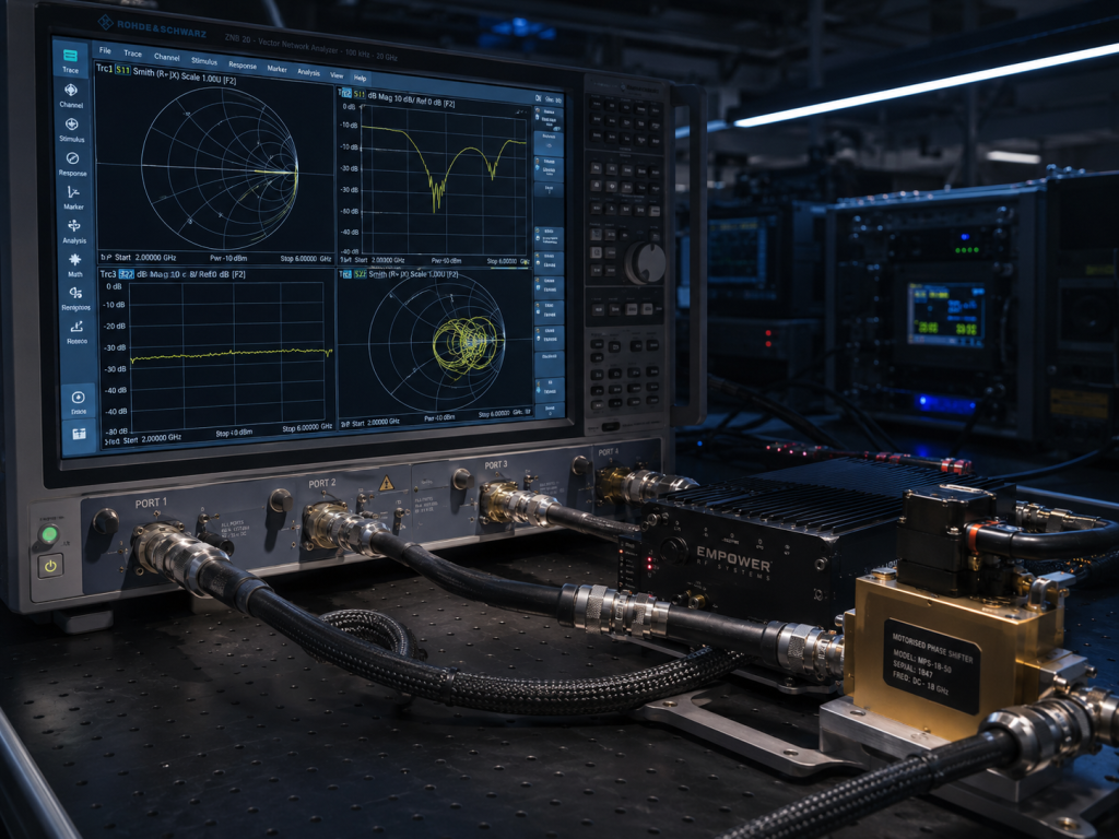
Here is the engineering truth… regarding the uncompromising testing protocols at the CorelixRF manufacturing facility. We absolutely do not rely on calculated estimates or generalized assumptions. Every amplifier design undergoes rigorous stress testing against deliberate, massive impedance mismatches. During validation, the output port of the amplifier connects to a motorized phase shifter terminated in a severe mismatch, representing an infinite VSWR condition. We drive the amplifier to its maximum rated output power and continuously rotate the phase shifter through a full 360 degrees. This sweeps the voltage maximum across all possible phase angles, exposing the output matching network to the worst-case stress profiles. The module must survive this physical treatment for extended periods without degradation in gain or efficiency once returning to a matched load. Only hardware passing these brutal assessments qualifies for serial production.
Why Must We Reject Theoretical Simulation In Favor Of Hard Empirical Data?
Consider the physical reality… that software simulations frequently fail to capture the chaotic nature of actual field deployments. While harmonic balance and electromagnetic simulation tools provide an excellent starting point for circuit design, they assume perfect material properties and idealized boundary conditions. An RF software model rarely accounts for the exact galvanic corrosion rate of a specific N-type connector exposed to coastal salt spray, nor does it predict the precise thermal fatigue of a solder joint after two years of mechanical vibration. CorelixRF mandates that all final specifications derive directly from empirical testing on the laboratory bench. We measure exact current draws, precise insertion losses, and factual thermal gradients using calibrated vector network analyzers and physical thermal imaging. Relying strictly on simulated results creates a dangerous false confidence that rapidly collapses when confronted with real-world physical degradation.
| Metric Evaluated | Software Simulation Prediction | Empirical Laboratory Truth |
| Max Current Draw at 100W | 18.5 Amps (Ideal Matched) | 20.0 Amps (Real-world Load) |
| Flange Temperature Rise | +45°C (Uniform sink) | +58°C (Center Die Hotspot) |
| VSWR Trip Response Time | 2.0 Microseconds | 3.5 Microseconds |
How Does Intelligent Output Power Foldback Prevent Catastrophic System Shutdowns?
Let’s examine the raw data… behind automatic leveling and hardware foldback circuits. When mechanical failure caused by inferior connectors initiates a sudden VSWR event, completely shutting down the amplifier interrupts critical communication links, effectively taking the base station offline. Instead of forcing a hard fault, advanced base station amplifiers utilize an intelligent power foldback loop. As the reflected power crosses a predefined safe threshold, the internal control circuitry linearly reduces the forward drive signal. The amplifier continues to operate, albeit at a reduced output power, maintaining the communication link while keeping the transistor junction temperatures strictly within safe operating limits. Once the physical obstruction clears or the antenna icing melts, the VSWR returns to a normalized state, and the amplifier automatically ramps the power back to the nominal level. This dynamic hardware response maximizes system uptime and strictly controls thermal dissipation under adverse load conditions.
Designing and deploying robust RF architecture requires an unyielding adherence to physical reality. The engineering truth remains brutally clear: raw wattage specifications hold zero functional value if the hardware cannot survive the severe electrical reflections generated by RF cable long-distance insertion loss and mechanical failure caused by inferior connectors. CorelixRF builds amplification infrastructure governed exclusively by the laws of physics, prioritizing indestructible VSWR protection, rigorous thermal management, and empirical laboratory validation. We heavily engineer the CRF-PA-5700M5900M-100W to operate reliably when external physical components inevitably fail in the field. Do not leave your high-frequency infrastructure vulnerable to preventable mechanical degradation and catastrophic transistor failure. Contact the CorelixRF engineering team today to review the complete, uncompromising technical data sheets and secure your next outdoor deployment.
FAQ
Q1: What is the maximum acceptable VSWR for continuous operation of the CRF-PA-5700M5900M-100W without triggering the foldback protection?
A1: The module allows continuous operation into a VSWR of 1.5:1 without any power reduction. Once the reflection coefficient exceeds this hard boundary, the internal directional couplers instruct the logic circuit to initiate proportional power foldback to protect the GaN transistors from excessive thermal dissipation.
Q2: How exactly does long-distance insertion loss affect the amplifier’s input drive requirements?
A2: Long-distance insertion loss on the input side attenuates the driver signal. If the system requires +10 dBm to reach saturation, but the input cable introduces 3 dB of loss, the driver stage must supply +13 dBm. Failure to account for this attenuation starves the final amplifier stage, preventing it from reaching its rated nominal power.
Q3: Can the hardware VSWR protection mechanism be manually disabled during laboratory bench testing?
A3: No. CorelixRF hardwires the high-speed VSWR detection and foldback loop directly into the bias sequencing circuitry. Permitting a manual override introduces an unacceptable risk of instantaneous device failure during physical testing. The protection remains permanently active.
Q4: What specific maintenance protocols mitigate mechanical failure at the connector junctions in outdoor deployments?
A4: System integrators must mandate the use of calibrated torque wrenches to achieve exact mating pressure, apply industrial-grade weatherproof sealing tape over all external junctions, and implement annual sweep testing utilizing a portable Vector Network Analyzer (VNA) to detect microscopic impedance shifts before they escalate into severe VSWR events.
Q5: Why is empirical laboratory data prioritized over advanced electromagnetic simulation data in CorelixRF physical specifications?
A5: Electromagnetic simulations cannot accurately replicate the unpredictable, compounding variables of mechanical stress, galvanic corrosion, and dynamic thermal fatigue found in outdoor environments. We rely exclusively on empirical data gathered from brutally destructive bench testing to establish guaranteed survival limits.
Turn VSWR behavior into factory acceptance evidence
High VSWR protection should be defined with mismatch scenario, foldback or shutdown threshold, recovery logic, alarm output, thermal limit and FAT evidence. This makes protection claims measurable for procurement.
Recommended next step: send the operating band, output power target, duty cycle, load condition, control interface, protection or thermal limits and required FAT documents. CorelixRF can review this How to Prevent Hardware Failure With a Strict VSWR Protection Mechanism? requirement against standard RF amplifier platforms, RF front-end options and controlled customization paths.