
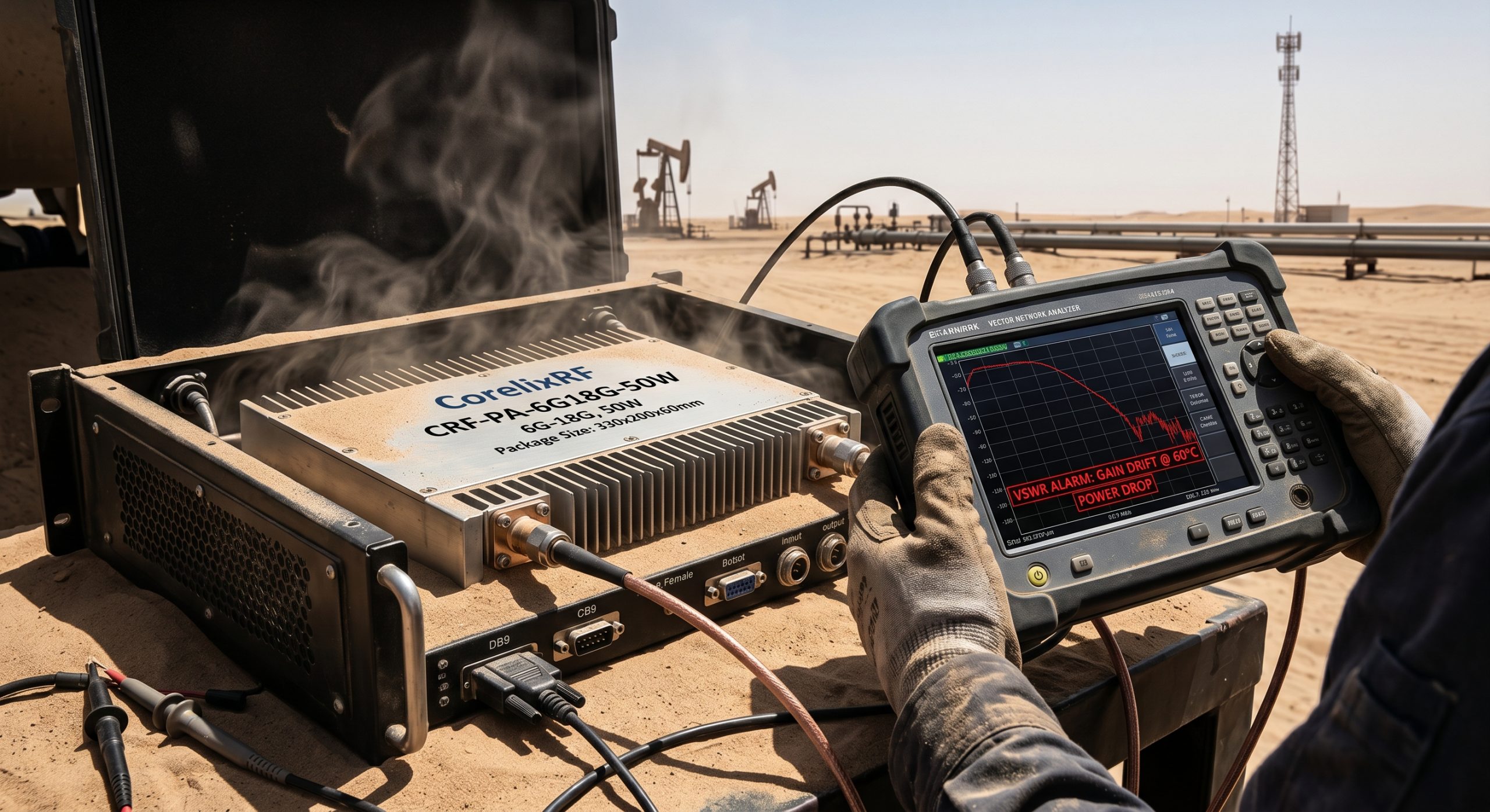
System integrators frequently face unexplained VSWR alarms during desert deployments. A communications node working perfectly indoors suddenly drops output power outdoors. We address thermal drift problems head-on today. Relying on twenty years of radio frequency engineering experience, my team designs hardware capable of surviving extreme realities. I detail specific diagnostic steps below. This article analyzes hardware failures logically. We provide actionable engineering truths for frontline operators.
1. What Causes VNA Curve Collapses in Middle Eastern Deserts?
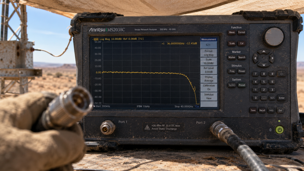
You deploy a satellite communication link near a drilling rig. Everything tests fine back home inside air-conditioned rooms. Here’s the deal. Out here among sand dunes, ambient temperatures exceed normal limits rapidly. Sun loading bakes metal enclosures mercilessly. An operator connects a portable Vector Network Analyzer looking for faults. High-frequency traces on that VNA screen suddenly sag unexpectedly. We often see engineers mistakenly blame antenna connectors initially. They waste hours swapping coaxial cables under intense heat. That approach ignores underlying physical physics completely. A real culprit hides inside your amplification chain. Semiconductors behave differently when junction temperatures spike dangerously high. Gain drops predictably as thermal saturation occurs. This phenomenon ruins link budgets instantly. Your system loses critical data packets randomly. Troubleshooting requires understanding device-level physics rather than guessing blindly. We must look closely at how amplifiers react inside sealed boxes. A simple lab test cannot replicate harsh desert conditions accurately. High-frequency vibration from drilling equipment complicates signal integrity further. Fine desert sand penetrates poorly sealed chassis easily. This grit coats internal components thoroughly. Heat dissipation drops dramatically when components wear a sand blanket. Your VNA shows this degradation as a collapsed high-frequency response. We mandate strict environmental chamber testing before any field deployment. This process saves immense frustration later.
2. How Does Thermal Drift Alter Link Budgets Suddenly?
Engineers calculate path loss using nominal output values. Those spreadsheets assume constant performance from active components. You might be wondering. Why do carefully calculated margins vanish during midday operations? Amplification transistors exhibit negative temperature coefficients naturally. Electron mobility decreases inside gallium arsenide materials when heated. This physical constraint reduces overall gain incrementally. A module delivering fifty watts at twenty-five degrees Celsius might only output thirty watts later. System controllers sense this drop immediately. They command pre-amplifiers to drive harder. This over-drive condition creates cascading failures across multiple stages. Heat dissipation becomes impossible within tightly packed chassis. Harmonics increase beyond acceptable limits quickly. Spurious emissions leak into adjacent frequency bands. The entire communication channel becomes unstable. We measure these effects using directional couplers and power meters. Real-world deployment demands rigorous thermal profiling beforehand. Ignoring these mechanisms guarantees premature equipment degradation. A sudden three decibel drop equates to half your transmitted power vanishing. Radar systems lose tracking resolution rapidly under these conditions. Target acquisition becomes impossible when link budgets fluctuate wildly. Engineers must design systems featuring active temperature compensation circuits. Passive cooling alone fails miserably near Middle Eastern pumping stations. We have seen entire racks melt down due to thermal runaway. Proper hardware selection prevents such catastrophic operational failures.
| Parameter | Lab Condition | Field Condition | Impact on System |
| Ambient Heat | 25°C | 60°C | Rapid thermal saturation |
| Air Quality | Clean Room | Blowing Sand | Blocked ventilation paths |
| Vibration | Zero | High (Drilling) | Mechanical stress on joints |
| Humidity | Controlled | High Salt Fog | Accelerated corrosion rates |
3. Why Do Standard Components Fail Near Pumping Stations?
Commercial off-the-shelf modules utilize cheap substrates. Designers rely upon large aluminum heatsinks for cooling purposes. What’s the real story? Desert environments feature high ambient heat combined with blowing sand. Fan-forced air cooling systems ingest abrasive dust quickly. Vents clog up within days of installation. Internal airflow stops completely. Standard radio frequency components cannot survive such severe choking. Solder joints stress under continuous thermal cycling. Connectors loosen due to heavy vibration from nearby drilling machinery. Ground returns degrade silently over time. This creates intermittent faults that baffle maintenance crews. An engineer might measure correct voltage levels during morning inspections. By afternoon, that same node triggers multiple software alarms. We see these failures across various third-party hardware routinely. Cheap designs lack adequate thermal mass near critical junctions. They also omit necessary software compensation routines. True engineering requires building robust solutions from scratch. We analyze specific failure modes deeply. Salt fog from nearby coastal operations corrodes exposed traces rapidly. Standard conformal coatings blister and peel away under sixty-degree ambient heat. Moisture penetrates these cracks during cooler night hours. This creates microscopic shorts across radio frequency matching networks. Your perfectly tuned amplifier suddenly presents a massive mismatch. Hardware dies quietly without proper environmental hardening.
4. What Are The Hidden Traps Within Forward Power Monitoring?
Field technicians trust built-in telemetry data implicitly. They read diagnostic screens expecting accurate reflections of reality. This is where it gets interesting. Telemetry circuits themselves suffer from thermal drift. A diode detector measuring forward power changes characteristics when hot. The detection voltage output shifts unpredictably. An operator sees a normal reading while actual transmission strength drops. This false confidence delays critical interventions during outages. You need external verification using calibrated spectrum analyzers. We recommend probing specific test points directly. Monitor DB9 Pin six for forward detection voltage output. Compare this value against known calibration curves. Realizing your measurement tools lie represents a harsh lesson. We learned this through painful field experiences. Designing reliable monitoring requires temperature-compensated detector circuits. Only then can remote operators trust their dashboard metrics. Hardware must report true states regardless of external climate conditions. A false positive reading masks underlying amplifier degradation dangerously. An engineer might assume antenna arrays failed instead. This leads to costly and unnecessary equipment replacements. We mandate verifying internal sensors against external laboratory-grade equipment. Your troubleshooting methodology must account for drifting sensor baselines. Trusting uncalibrated data wastes valuable engineering hours constantly.
| Pin Number | Function | Signal Type | Field Reality Trap |
| DB9 Pin 5 | Input Monitor | DC Voltage | False low readings |
| DB9 Pin 6 | Forward Power | DC Voltage | Thermal drift masks drops |
| DB9 Pin 7 | Reverse Power | DC Voltage | Delayed VSWR alerts |
| DB9 Pin 8 | Temp Monitor | DC Voltage | Sensor placement skews data |
5. How Does CorelixRF Address High-Temperature Realities?
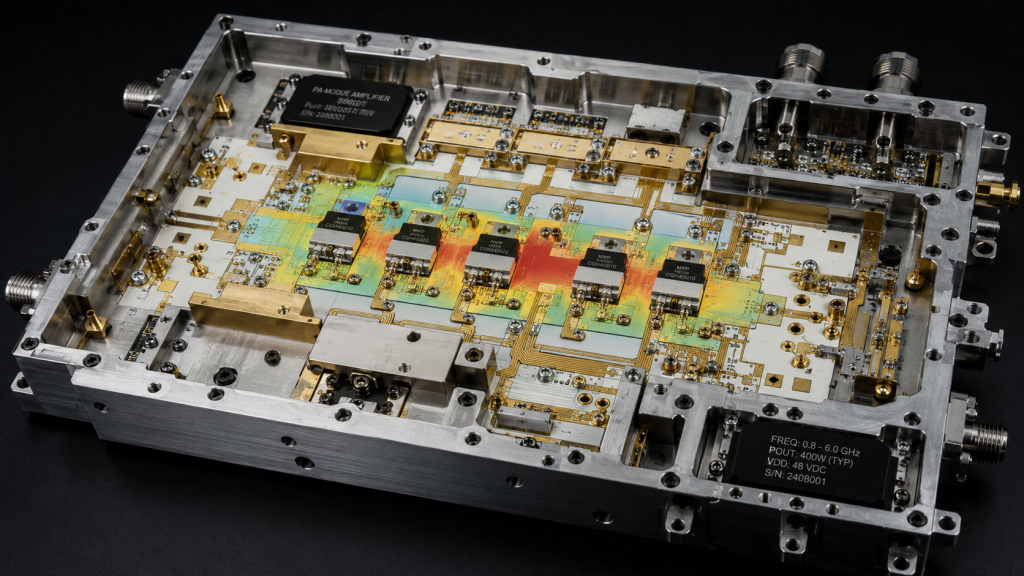
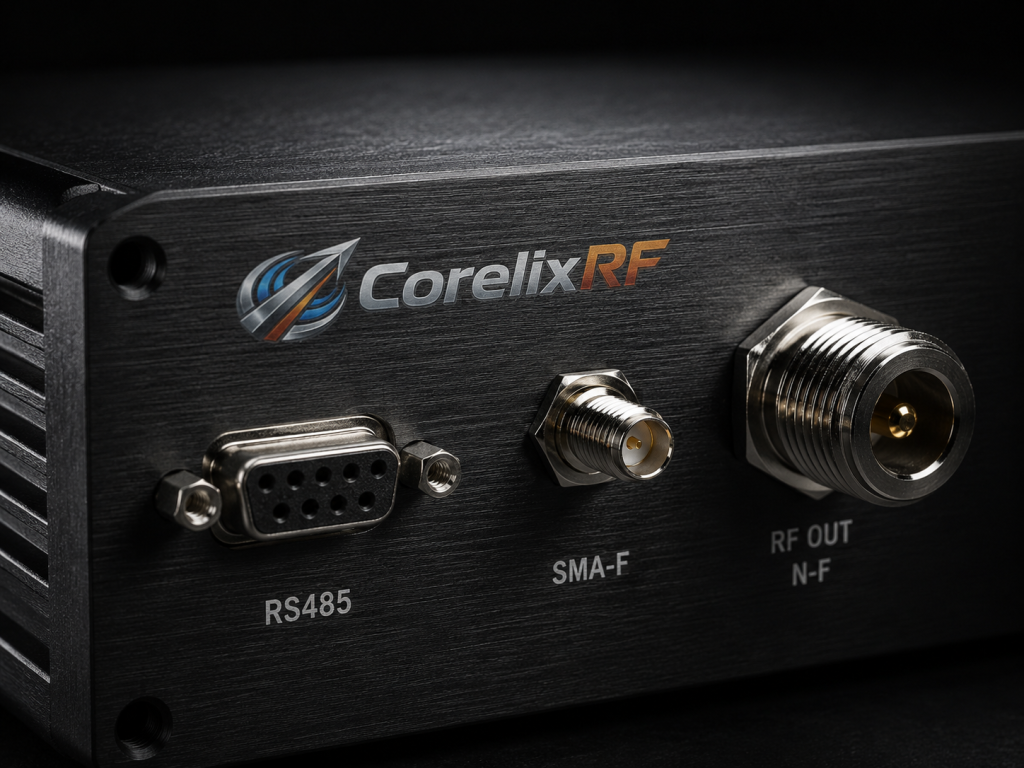
Solving extreme thermal challenges demands superior semiconductor choices. Legacy technologies simply cannot handle concentrated power dissipation. Ready for the good part? Our team utilizes advanced GaN technology. Gallium Nitride offers superior thermal conductivity compared to older alternatives. This material allows higher operating temperatures without catastrophic gain collapse. The CRF-PA-6000M18000M-50W represents our commitment towards reliable performance. It delivers fifty watts across a massive bandwidth. We designed package sizes specifically for optimal heat spreading. The 330 x 200 x 60 mm chassis acts as a massive thermal reservoir. This physical volume prevents rapid temperature spikes during peak transmission bursts. Our engineers focused heavily on efficient DC-to-RF conversion. Less wasted energy means less internal heating overall. This hardware provides a stable fifty decibel gain profile. We build products designed for brutal realities. A twenty-eight volt nominal power supply drives this beast efficiently. We avoided placing sensitive control logic near high-power stages. This spatial separation guarantees logic board survival during thermal events. An SMA-Female input connector provides a reliable connection point. The N-Female output connector handles fifty watts easily. We supply mechanical drawings for exact installation reference. Every detail reflects our obsession with engineering truth.
| Model Number | Frequency Range | Gain | Rated Output |
| CRF-PA-6000M18000M-50W | 6,000-18,000 MHz | 50 dB | 50 W |
| Package Size | Dimensions | Cooling Method | Operating Temp |
| 330 x 200 x 60 mm | Custom Frame | Air cooling | 0 to 50 Celsius |
6. Why Does Wideband Flatness Matter Across 6,000-18,000 MHz?
Electronic warfare and radar systems utilize wide frequency sweeping. Signals bounce across vast spectral ranges rapidly. But here’s the kicker. Amplifiers rarely maintain flat responses across twelve gigahertz bandwidths. A unit might perform perfectly at eight gigahertz. That same module could show severe roll-off near eighteen gigahertz. Such inconsistencies create massive calibration headaches for system integrators. The CRF-PA-6000M18000M-50W maintains a tight flatness profile. Variations stay within negative four to positive four decibels. This precision ensures predictable signal strength across all channels. We measure this parameter strictly during factory testing. Test conditions demand a fifty ohm system impedance continuously. Poor flatness distorts complex modulation schemes irreparably. Data links suffer higher bit error rates consequentially. We guarantee our specifications match actual delivered units. Engineers can rely upon our published datasheets confidently. A flat response simplifies pre-distortion algorithms immensely. Software developers waste fewer cycles correcting hardware deficiencies. Your entire transmission chain behaves predictably under load. We verify flatness using automated scalar network analyzer sweeps. Every module receives comprehensive documentation before leaving our factory. You receive test data files for your project reviews. We hide nothing from our engineering clients.
7. How Does The RS485 Control Interface Streamline Diagnostics?
Remote oilfield locations make physical access incredibly difficult. Sending a technician out takes days of travel. It boils down to this. You must control and monitor equipment remotely. Our design incorporates a robust RS485 serial communication interface. DB9 pins one and two handle this differential signaling. RS485 survives noisy electromagnetic environments better than standard USB connections. Pumping stations generate massive electrical transients constantly. This interface allows central hubs to adjust attenuation remotely. Input ranges from zero to three volts dictate operational parameters. Operators can reduce output power if temperatures climb dangerously. This proactive management prevents catastrophic hardware failures. Pin eight provides direct temperature detection voltage output. Software algorithms can track thermal trends historically. This data informs predictive maintenance schedules efficiently. Smart integration saves companies immense operational costs over time. Pin three controls PTT functions smoothly. Applying three point three volts turns active amplification on. Zero volts disables transmission immediately. This rapid switching capability supports advanced radar pulsing techniques. We built an interface designed for serious professional usage. There are no consumer-grade connectors here. Industrial automation requires proven and reliable physical layers.
| DB9 Pin | Description | Specification | Use Case |
| Pin 1 & 2 | Serial Comm | RS485 (-) / (+) | Remote telemetry |
| Pin 3 | PTT Control | 3.3V ON, 0V OFF | Radar pulsing |
| Pin 4 | Attenuation | 0-3.0V DC | Power reduction |
| Pin 8 | Temp Monitor | Analog Output | Thermal tracking |
8. What Built-in Protections Ensure Survival Against VSWR Alarms?
Antennas break due to high winds frequently. Coaxial cables snap under heavy mechanical stress. Here is the bottom line. Broken transmission lines reflect energy back into your amplifier. This reverse power destroys output transistors instantaneously. Our CRF-PA-6000M18000M-50W features comprehensive built-in protection. Internal circuitry defends against over-voltage and over-temperature states actively. We specifically engineered robust VSWR protection mechanisms. The system handles an input VSWR of two to one safely. It detects reverse power anomalies quickly. Module shutdown prevents permanent internal damage. It monitors DB9 pin seven for reverse detection voltage output constantly. We designed these safeguards based upon real-world disaster analysis. Unprotected units become total losses during cable faults. Our hardware survives these common deployment accidents. An optional built-in coupler provides even tighter monitoring capabilities. This allows integrators to sample forward and reverse paths accurately. Protection circuits must act faster than thermal destruction occurs. Our proprietary logic gates cut bias voltages within microseconds. This rapid response saves fifty-watt GaN transistors from certain death. We consider these features mandatory for military and industrial applications. Field replacements cost far more than initial hardware investments.
9. How Do We Validate Gain Stability During System Integration?
Proper testing requires mimicking expected deployment conditions. You cannot rely upon standard laboratory results blindly. You might be wondering. How should a team stress-test an entire assembly? We recommend placing enclosures inside thermal chambers. Run systems at full capacity while ramping ambient heat. Monitor noise floor metrics continuously during this cycle. The CRF-PA-6000M18000M-50W maintains a negative forty dBm per MHz floor. Watch for any sudden jumps indicating thermal runaway. Inject a zero dBm input signal. Verify fifty watt rated outputs remain steady. Use automated scripts communicating via DB9 ports. This approach uncovers weak links before shipping products abroad. We supply test data and pattern files for project reviews. Integrators deserve absolute transparency regarding hardware limitations. Proper validation prevents embarrassing failures in front of end clients. Test units utilizing fifty ohm dummy loads initially. Introduce controlled mismatches using stub tuners later. Document exactly how protection circuits engage. This characterizes system recovery times accurately. We utilize advanced spectrum analyzers for harmonic measurements. Keep harmonics strictly below negative ten decibels. These steps forge a path toward absolute reliability.
| Validation Step | Test Equipment | Pass Criteria | Notes |
| Thermal Cycle | Chamber | Continuous 50W | Ramp 0 to 50 Celsius |
| VSWR Check | Stub Tuner | Auto-Shutdown | Test reverse power pin |
| Flatness Test | VNA | -4 to 4 dB | Sweep 6G to 18G |
| Noise Floor | Spec Analyzer | -40 dBm/MHz | Check at maximum gain |
10. What Are The Final Considerations For Deployment In Deserts?
Every installation detail matters when fighting severe heat. Mechanical mounting choices directly impact thermal dissipation efficiency. This is where it gets interesting. Ensure adequate clearance around heat sink fins. Blocked airflow negates all internal engineering efforts completely. Utilize high-quality thermal pastes between mating surfaces. Verify DC twenty-eight volt power supplies remain clean. Voltage ripples introduce unwanted noise into RF chains. Keep harmonics strictly below negative ten decibels relative to carrier. Maintain spurious emissions below negative sixty decibels. These practices guarantee regulatory compliance across international borders. CorelixRF provides mechanical drawings for installation reference purposes. Final dimensions always match production units perfectly. We stand behind specifications with absolute certainty. Rigorous preparation guarantees long-term success outdoors. A robust ground connection prevents dangerous chassis voltage build-up. Always connect Ground Return terminals securely. Verify all SMA and N-Type connectors using calibrated torque wrenches. Over-tightening damages internal dielectrics permanently. Loose connections create intermittent micro-arcing during high-power bursts. Attention to mechanical details separates professionals from amateurs. Our thirty years of manufacturing experience informs these recommendations. Do not skip basic mechanical checks under any circumstances.
Final Thoughts Understanding physical failure mechanisms prevents catastrophic system outages. Thermal drift destroys uncompensated amplification chains rapidly. CorelixRF solutions rely upon advanced materials and robust protection circuitry. System integrators must prioritize realistic environmental testing protocols. Implementing strict quality frameworks like ISO 9001 and GJB 9001C guarantees consistency. Contact our engineering team today to review data files for your next critical project.
FAQ
- Q1: What is thermal drift in RF amplifiers?
- Thermal drift happens when semiconductor junction temperatures rise, causing electron mobility to drop. This physical change reduces overall amplifier gain predictably under intense heat.
- Q2: How does GaN technology work to reduce heat?
- Gallium Nitride features a significantly higher thermal conductivity compared to traditional silicon. It moves heat away from sensitive junctions much faster, preventing thermal saturation.
- Q3: Why do VSWR alarms happen in desert environments?
- High temperatures and heavy vibration from drilling machinery cause connectors to loosen or fail. This mechanical breakdown reflects power back into amplifiers, triggering VSWR alarms.
- Q4: How can engineers monitor temperature remotely?
- Engineers utilize DB9 interfaces on our amplifiers. Pin eight outputs an analog voltage corresponding to internal temperature, allowing remote tracking via RS485 connections.
- Q5: What built-in protections does the CRF-PA-6000M18000M-50W have?
- The unit actively monitors for over-voltage, over-temperature, over-drive, and high VSWR conditions. It automatically shuts down bias circuits to prevent catastrophic hardware destruction.
Convert thermal risk into measurable RFQ requirements
Thermal reliability should be specified with output power, duty cycle, ambient range, airflow or baseplate path, soak time, allowed gain drift and alarm behavior. These details help CorelixRF match the request to a standard or modified amplifier platform.
Recommended next step: send the operating band, output power target, duty cycle, load condition, control interface, protection or thermal limits and required FAT documents. CorelixRF can review this How to Prevent RF Amplifier Thermal Drift in Extreme Heat? requirement against standard RF amplifier platforms, RF front-end options and controlled customization paths.