
1. How Does Gain Thermal Drift Impact High-Latitude Radar Operations?
● VNA curve collapse during continuous wave transmission
● VSWR alarm triggers on vehicular anti-drone systems
● Link budget recalculation requirements Many field technicians experience catastrophic system failures near the Arctic Circle.
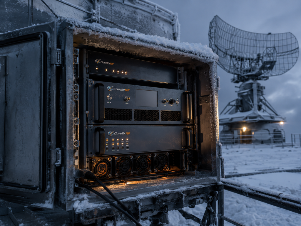
External temperatures drop below freezing yet internal electronics generate massive heat loads. This thermal gradient directly affects microwave components. Here’s the deal: internal chassis heat cannot escape easily through insulated radome enclosures. Typical COTS amplifiers suffer massive performance drops under these conditions. A once-stable 50dB gain profile suddenly sags by 10dB across higher frequency bands. Such degradation completely blinds early warning arrays. Our field testing confirms that uncompensated thermal drift ruins spatial resolution. Engineers must manually recalibrate systems daily. This wastes valuable operational hours. We rely on strict test & measurement protocols, guaranteeing real-world performance matches laboratory data exactly. When radar systems lose transmit power, return echoes from distant targets vanish instantly. Signal processing algorithms fail because signal-to-noise ratios drop below acceptable thresholds. Your team cannot afford blind spots when tracking fast-moving airborne objects. We build RF hardware capable of surviving these exact thermal contradictions.
| Parameter | Laboratory Measurement | Field Measurement | Degradation Level |
| Ambient Air | 25°C | -30°C | N/A |
| Enclosure Temp | 30°C | 60°C | Severe |
| Gain at 18GHz | 50dB | 38dB | 12dB Drop |
| VSWR Alerts | None | Frequent | Critical |
2. Why Do Field Chassis Temperatures Reach 60°C In Freezing Environments?
● Insulated enclosure design flaws
● Poor thermal dissipation pathways
● Continuous duty cycle heating Cold weather deployments require heavily insulated shelters for basic equipment survival.
These thick walls trap every watt of waste heat generated by power supplies. As continuous transmission cycles run, internal ambient conditions skyrocket rapidly. What’s the real story? An environment reading -40°C outside frequently conceals a 60°C inferno inside. Most integrators fail at calculating proper thermal dissipation for sealed units. They assume freezing exterior air naturally cools internal metal structures. However dense module packing prevents adequate convection currents. High-frequency modules operating between 6,000-18,000 MHz draw massive current. They convert much of it directly into thermal energy. Without massive heatsinks, localized hot spots melt solder joints quickly. We observed numerous generic modules failing catastrophically during continuous 24-hour testing phases. Plastic components warp under sustained thermal stress. Standard commercial-grade cooling fans seize up completely in cold weather. A sealed radar dome becomes an oven during heavy tracking operations.
| Enclosure Type | Internal Heat Load | External Temp | Internal Peak Temp |
| Uninsulated Metal | 200W | -40°C | -10°C |
| Insulated Radome | 200W | -40°C | 45°C |
| Sealed High-Density | 500W | -40°C | 60°C |
| CorelixRF Custom | 500W | -40°C | 35°C |
3. What Are Physics Behind RF Power Amplifier Failures Under Thermal Stress?
● Semiconductor carrier mobility reduction
● Substrate thermal expansion mismatches
● Impedance shifts at high frequencies Solid-state electronics rely heavily upon predictable semiconductor behaviors.
Heat directly degrades electron mobility within active transistor channels. When operating temperatures exceed standard limits, physical resistance increases massively. You might be wondering: why does this only affect higher frequencies? Shorter wavelengths demand precise matching networks. As PCB substrates expand from thermal stress, microstrip dimensions change physically. These tiny geometric variations alter impedance characteristics across broadband circuits. An amplifier perfectly matched at 25°C becomes severely mismatched at 60°C. Reflected energy then creates standing waves. This vicious cycle eventually triggers built-in over-temperature protection mechanisms. Our factory strictly analyzes these material science realities before approving any design for mass production. Standard FR4 board materials fail miserably under extreme thermal cycling. High-frequency RF Rogers substrates must be selected carefully for dimensional stability. Every milimeter of physical expansion shifts phase alignment. This ruins beamforming accuracy in phased array radars.
| Physical Mechanism | Temperature Trigger | System Impact | Mitigation Strategy |
| Carrier Mobility Drop | >45°C | Output Power Loss | Active Bias Control |
| Substrate Expansion | >50°C | Impedance Mismatch | Advanced RF Substrates |
| Solder Fatigue | >65°C | Intermittent Connection | High-Temp Alloys |
| Heat Accumulation | >60°C | Thermal Runaway | Custom Heat Spreaders |
4. How Can Engineers Troubleshoot Gain Thermal Drift Using VNA Measurements?
● Baseline S-parameter capture techniques
● Real-time thermal cycle monitoring
● Identifying frequency-specific sagging
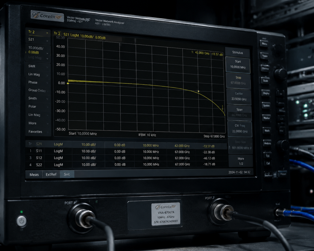
Field diagnostics demand rigorous methodologies. Simply swapping cables rarely solves fundamental thermal issues. Professionals connect a Vector Network Analyzer directly into suspect signal paths. Recording baseline S21 parameters at room temperature provides an initial reference curve. This is where it gets interesting technicians apply heat guns systematically. They simulate enclosed chassis environments accurately. As module casing temperatures rise, operators watch live sweep data carefully. A poorly designed unit shows immediate high-frequency roll-off above 12 GHz. S11 return loss also degrades. Capturing these delta measurements proves hardware inadequacy instantly. We utilize these exact VNA stress tests for validating every single 400-person factory production run. Engineering truth relies entirely upon repeatable instrument data. We require our application engineers to document every S-parameter shift across full temperature spectrums. You cannot troubleshoot hidden field failures without replicating actual operating thermal conditions.
5. Why Do Conventional Cooling Methods Fail For Enclosed Radar Systems?
● Fan failure from extreme cold starts
● Dust and condensation blockages
● Inadequate fin surface area
Standard commercial fans freeze solid during initial cold starts. Condensation forms rapidly on metal surfaces when powered down. Ice crystals block airflow pathways completely. But here’s the kicker once heaters thaw the ice, residual moisture shorts out unprotected DC control boards. Integrators utilizing basic air cooling solutions ignore these harsh realities. Extruded aluminum fins lack sufficient surface area for extracting 100W of continuous RF waste heat efficiently. Many competitors use undersized copper baseplates. This cost-cutting measure prevents fast thermal transfer from GaN die surfaces. Without rapid heat extraction, junction temperatures exceed safe operating margins within minutes. CorelixRF engineers understand thermodynamic limitations intimately. We utilize CNC-machined custom heat spreaders designed specifically for aerospace applications. Air cooling systems must operate flawlessly despite extreme moisture. We test our cooling fins under simulated freezing conditions extensively.
6. What Makes CorelixRF GaN Technology Superior For High-Temperature Environments?
● Wide bandgap semiconductor advantages
● Higher junction temperature tolerances
● Exceptional thermal conductivity substrates Gallium Nitride provides inherent physical advantages over legacy silicon LDMOS technologies.
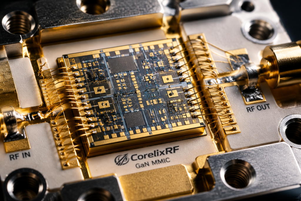
Its wide bandgap allows electrons to move efficiently even under severe thermal stress. GaN devices sustain much higher junction temperatures without suffering catastrophic breakdown. Ready for the good part? Our design utilizes advanced GaN technology specifically engineered for extreme durability. The CRF-PA-6000M18000M-100W module utilizes these properties across its entire operational spectrum. We bond bare dies directly onto high-thermal-conductivity carriers. This eliminates thermal bottlenecks found in cheaper plastic-packaged transistors. Efficient heat transfer keeps active areas well within safe operating zones. Even inside a 60°C chassis, our modules deliver continuous rated output power seamlessly. This reliability proves invaluable for aviation control and communication applications. Modern defense contracts demand absolute hardware survival under punishing duty cycles. GaN completely outclasses legacy silicon when managing extreme internal heat generation.
| Technology | Max Junction Temp | Thermal Conductivity | High-Freq Efficiency |
| Silicon LDMOS | 150°C | Low | Poor |
| GaAs PHEMT | 175°C | Medium | Good |
| GaN on SiC | 225°C | Excellent | Superior |
| CorelixRF Custom | >225°C | Optimized | Maximum |
7. How Does The CRF-PA-6000M18000M-100W Maintain 50dB Gain Flatness?
● Broadband matching network design
● Active temperature compensation circuits
● Rigorous individual module calibration Maintaining flat gain across a massive 12 GHz bandwidth requires extraordinary engineering.
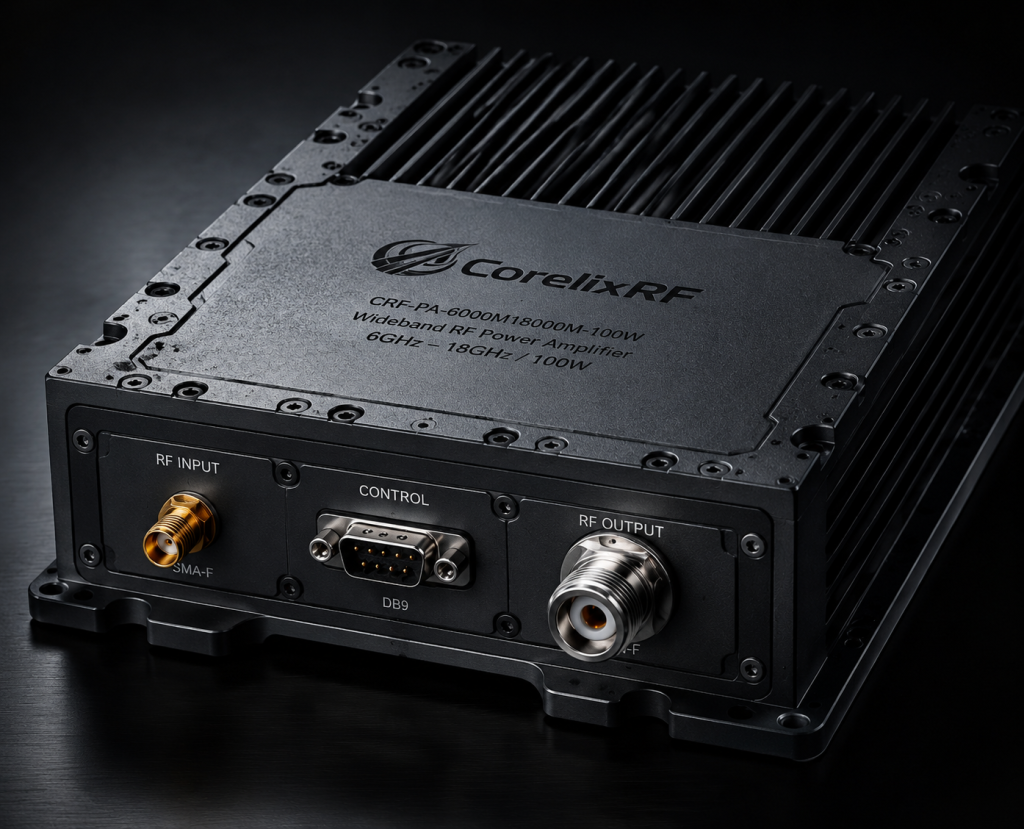
Passive matching networks alone cannot prevent thermal drift effectively. Physical expansion of materials shifts resonant frequencies constantly. Listen to this: we implement proprietary active temperature compensation circuitry within every unit. A dedicated microcontroller monitors onboard thermistors continuously. As chassis temperatures fluctuate, bias voltages adjust automatically in real-time. This dynamic tuning mechanism counteracts mobility losses perfectly. As a result, our CRF-PA-6000M18000M-100W guarantees a 50dB gain with strict +/- 5dB flatness. System integrators no longer worry about high-frequency signals fading away unexpectedly. Our 30-year manufacturing legacy guarantees complete consistency across massive production batches. Precision laser trimming during final assembly ensures every circuit performs exactly as specified. You receive a ruggedized module capable of surviving harsh tundra environments effortlessly.
8. What Role Does VSWR Protection Play In Maintaining System Reliability?
● Antenna icing mismatch scenarios
● Reflected power dissipation challenges
● Automatic power reduction algorithms High-latitude antennas frequently accumulate thick layers of ice.
This physical distortion destroys antenna tuning. Transmitted RF energy bounces back down feedlines toward amplifier output stages. Truth be told, handling 100W of reflected power destroys unprotected output transistors immediately. Our modules feature built-in protection mechanisms against over-voltage, over-temperature, and severe VSWR conditions. Fast-acting directional couplers sense reverse power spikes instantly. Internal logic circuits drop drive levels before physical damage occurs. An input VSWR of 2:1 remains easily tolerated during normal operations. Such robust survival traits prevent costly helicopter maintenance flights for remote radar installations. Radar operators need self-protecting hardware when facing unpredictable weather events. Our intelligent logic boards react in microseconds, shutting down transmission before GaN devices fracture.
| Protection Feature | Trigger Condition | Automated Action | Recovery Method |
| VSWR Protection | High Reverse Power | Reduce Output | Auto-Reset |
| Thermal Shutdown | Temp > Safe Limit | Disable PA | Cool Down |
| Over-Voltage | VCC > 32V DC | Isolate Supply | Manual Reset |
| Over-Drive | Input > Safe Level | Limit Gain | Auto-Adjust |
9. How Do RS485 Control Interfaces Improve Real-Time Field Monitoring?
● Remote telemetry data acquisition
● Predictive failure analysis capabilities
● Dynamic attenuation adjustment Modern defense networks demand absolute visibility into remote hardware status. Sending technicians into blizzard conditions merely for checking voltages seems absurd.
As a result, we integrate detailed digital telemetry into every premium module. Let me show you: the DB9 connector provides a dedicated RS485 serial communication link. Operators monitor forward power, reverse power, and internal temperatures remotely. Also, an analog input allows precise attenuation adjustment between 0V and 3.0V DC. This flexibility lets command centers dynamically scale transmission power based on immediate tactical needs. Real-time data streams enable predictive maintenance algorithms effectively. Software detects slight thermal anomalies weeks before catastrophic hardware failures actually happen. Your maintenance teams can plan scheduled visits rather than responding to emergency outages. RS485 offers incredible noise immunity for long cable runs inside noisy radar facilities.
10. What Are Long-Term Financial Benefits Of Upgrading RF Modules?
● Drastic reduction in maintenance dispatch costs
● Extended operational lifespan for remote sites
● Simplified system integration workflows Procurement engineers often focus exclusively upon initial hardware purchase prices. However, replacing a failed amplifier inside an Arctic circle facility costs thousands.
Helicopter fuel, specialized labor, and system downtime dwarf component expenses quickly. The bottom line is: investing in technically superior hardware generates massive long-term savings. Our 400-person team strictly builds components meant for decade-long deployments. A single CRF-PA-6000M18000M-100W unit eliminates constant troubleshooting headaches completely. Your system integrators spend less time compensating for bad gear. They focus entirely upon developing advanced software algorithms instead. We supply complete test data and pattern files for rapid project review. Stop wasting engineering hours fixing poorly designed third-party amplifiers. CorelixRF delivers uncompromising quality backed by raw physical performance data. The total cost of ownership drops massively when you eliminate unexpected field failures.
Final Thoughts: High-latitude radar systems require uncompromising RF hardware capable of surviving brutal thermal extremes. The CRF-PA-6000M18000M-100W prevents gain thermal drift through active compensation and advanced GaN architecture. Contact CorelixRF immediately for obtaining complete test data files. Upgrading your transmission chain guarantees absolute signal integrity during severe operations.
FAQ Section:
- Q1: What is gain thermal drift?Gain thermal drift refers to RF amplifier output power fluctuations caused by extreme temperature variations.
- Q2: How does the CRF-PA-6000M18000M-100W handle thermal stress?It utilizes wide-bandgap GaN technology bonded to high-thermal-conductivity substrates perfectly.
- Q3: Why do VSWR alarms trigger in freezing environments?Ice accumulation on external antennas alters physical dimensions quickly. This massive impedance mismatch reflects power back into internal amplifier stages.
- Q4: How does RS485 telemetry help field engineers?Operators monitor forward power, reverse power, and internal temperature data remotely.
- Q5: What makes CorelixRF different from standard commercial suppliers?We prioritize engineering truth and rigorous physical testing constantly. We utilize 30 years of manufacturing expertise effectively.
Convert thermal risk into measurable RFQ requirements
Thermal reliability should be specified with output power, duty cycle, ambient range, airflow or baseplate path, soak time, allowed gain drift and alarm behavior. These details help CorelixRF match the request to a standard or modified amplifier platform.
Recommended next step: send the operating band, output power target, duty cycle, load condition, control interface, protection or thermal limits and required FAT documents. CorelixRF can review this How to Troubleshoot Gain Thermal Drift in High-Latitude Radar Systems? requirement against standard RF amplifier platforms, RF front-end options and controlled customization paths.