

Passive node enclosures frequently trap extreme heat, causing severe RF output degradation when ambient air hits blistering levels. Remote unventilated base stations trigger catastrophic signal collapse under thermal strain. Deploying ruggedized hardware like our CRF-PA-6000M18000M-200W offers an uncompromising physical solution for harsh realities. Two decades spent measuring fried modules taught me one absolute engineering truth: thermal physics always destroys poor hardware designs.
1. Why Do Passive Nodes Suffer From Thermal Gain Drift?
Subtopics
● Unattended enclosure heat accumulation
● Microwave component thermal sensitivity
● Transistor junction behavior under stress
You might be wondering why remote installations experience such drastic power drops during mid-day operations. Passive nodes operate without active HVAC systems, relying entirely upon natural convection. When solar radiation bakes an outdoor cabinet, internal air easily exceeds sixty degrees Celsius. Semiconductors inside standard amplifiers possess negative temperature coefficients. Their transconductance plummets rapidly as surrounding heat rises uncontrollably. You will connect a VNA during a service call only find massive high-frequency roll-offs above twelve gigahertz. Solid-state devices lose efficiency sharply under these conditions. They turn applied DC power into wasted thermal energy instead of usable RF signals. This vicious cycle creates runaway conditions where nominal fifty-three decibel amplification collapses by several decibels within minutes. Generic solutions lack sufficient heatsink mass, causing rapid junction saturation. Real-world measurements routinely show complete signal collapse simply because designers assumed controlled laboratory environments during initial system calculations.
2. How Does a 60°C Field Chassis Differ From a 25°C Lab?
Subtopics
● Thermal gradient variations
● Component derating realities
● Test equipment blind spots
Here is the deal regarding bench testing versus actual site deployment. Engineers validate components inside perfectly air-conditioned rooms sitting exactly at twenty-five degrees Celsius. They measure beautiful flat curves showing perfect plus-minus five decibel tolerances across six thousand through eighteen thousand megahertz. However, moving that exact same hardware into a stifling remote box completely alters its operational physics. Heat conduction pathways degrade drastically when surrounding air offers zero cooling differential. I have seen countless technicians bring spectrum analyzers outdoors, scratching their heads when output power reads forty-two decibels instead of forty-seven decibels. Those missing decibels evaporated into pure thermal radiation. Laboratory setups never simulate massive localized power consumption trapped inside unventilated metal racks. That heavy dissipation requirement demands serious engineering, something typical commercial units simply cannot maintain when sucking in pre-heated sixty-degree air. You cannot cheat thermodynamics using cheap software compensation loops.
Environmental Parameter Comparison
| Condition | Lab Environment | Field Passive Node | Impact on RF Amplifier |
| Ambient Temp | 25°C | 60°C | Severe transistor junction stress |
| Cooling Source | AC conditioned air | Trapped hot air | Decreased thermal dissipation rate |
| Gain Drop | 0 dB (Baseline) | -3 dB to -8 dB | Significant link budget failure |
3. What Are The Symptoms Of Hidden Faults In Passive Nodes?
Subtopics
● High-frequency band collapse
● Frequent VSWR alarms
● Intermittent system reboots
What is the real story behind mysterious midnight system alarms driving maintenance teams crazy? Field integrators often misdiagnose thermal faults as antenna mismatches or cable degradation. A passive node baking under severe heat will suddenly trigger consecutive standing wave ratio warnings. Operators see screens flashing errors, assuming water ingress ruined their feedlines. In reality, thermal expansion inside cheap connectors alters impedance matching significantly. Your directional couplers start reading reflected energy because internal isolators failed under thermal strain. A classic symptom involves the WRD650 output waveguide flange heating unevenly, distorting cavity dimensions just enough cause mechanical detuning. If you hook up a portable network analyzer, return loss climbs from a healthy two-to-one ratio toward dangerous territory. These hidden failures do not trigger hard faults immediately. They degrade signal purity stealthily until entire data links drop out completely, leaving crews chasing ghost problems blindly.
4. How Do You Troubleshoot RF Power Output Drop On-Site?
Subtopics
● Directional power meter deployment
● Thermal camera inspection
● VNA calibration in hot environments
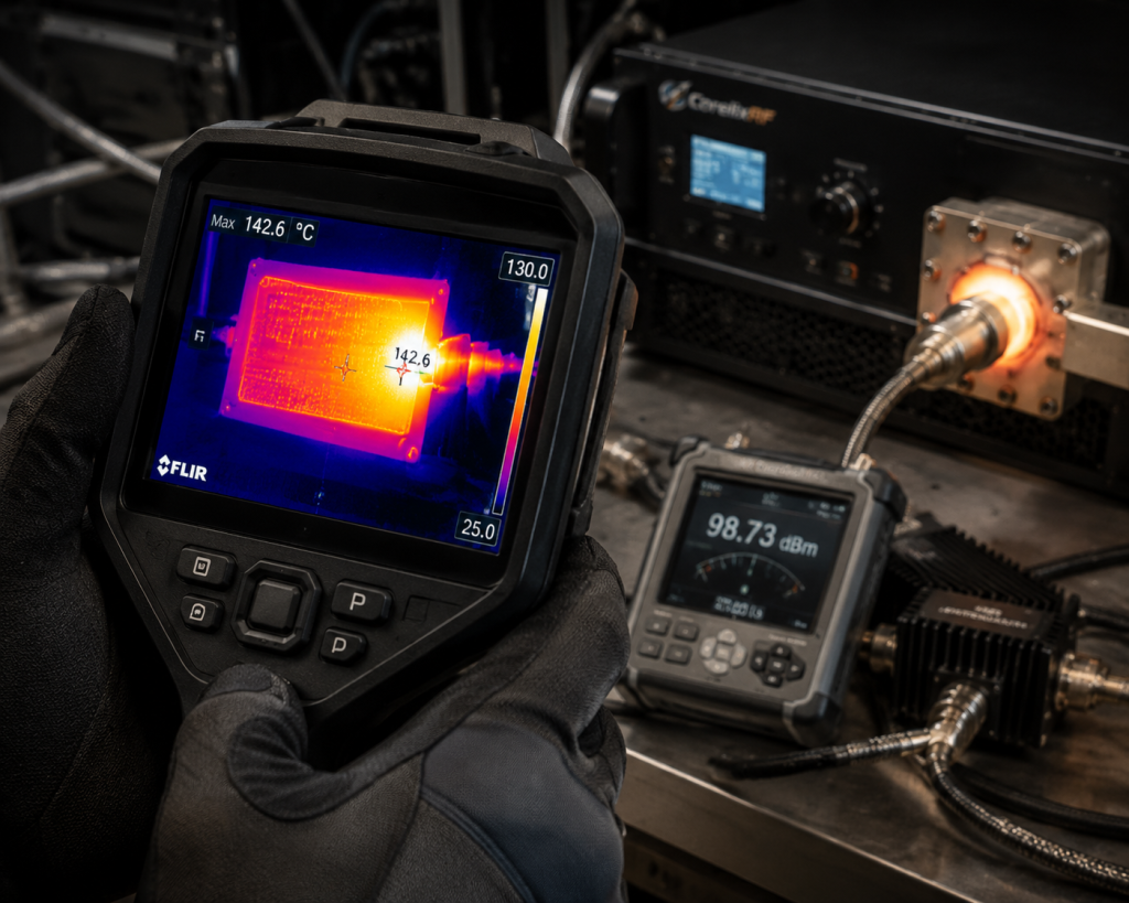
This is where it gets interesting for field technicians tasked with isolating phantom power drops. Leave your soft diagnostics behind immediately; grab a calibrated directional power meter alongside heavy-duty attenuators. Connect measuring gear directly at the N-Female input port first, verifying baseline drive signals remain near zero decibels milliwatt. Next, probe the SMA-F coupling connector while applying continuous wave test tones across different bands. If you measure expected output at lower frequencies but see massive attenuation near eighteen gigahertz, thermal saturation has crippled your final stage transistors. I strictly recommend using infrared thermal imaging cameras during active transmission. You will physically see localized hot spots glowing bright white around poorly seated output stages. Never trust built-in software telemetry alone. Sensors mounted far from actual active junctions often report dangerously false low temperatures. True engineering requires verifying raw physical voltages under maximum load conditions.
Field Diagnostic Steps
| Step | Tool Required | Target Measurement | Failure Indicator |
| 1 | Directional Power Meter | Forward RF Power | Output drops below 200W rating |
| 2 | Thermal Imaging Camera | Surface Temperature | Hot spots near output WRD650 flange |
| 3 | Portable VNA | Input Return Loss | VSWR exceeding 2:1 threshold |
5. Why Do Commercial Amplifiers Fail At High Temperatures?
Subtopics
● Inadequate heat sink mass
● Poor thermal interface materials
● Lack of hardware-level protection
Now consider this fundamental reality concerning mass-market communication hardware deployed outdoors. Budget manufacturers design equipment optimized primarily for low weight, sacrificing critical thermal mass required for absorbing transient heat spikes. They utilize thin aluminum extrusions paired with low-grade thermal paste degrading rapidly after repeated cycling. When drawing four thousand watts from an AC line, standard modules cannot shed excess heat fast enough through flimsy chassis walls. Solder joints experience micro-fractures due differing expansion rates between ceramic substrates and copper baseplates. Commercial gear relies heavily on slow software-based throttling. This delayed reaction acts far too late prevent microscopic silicon damage. Continuous operation near maximum saturation points accelerates electron migration within semiconductor channels. Eventually, you end up replacing entire sub-assemblies because one cheap transistor overheated catastrophically. Real industrial applications demand massive, deliberate engineering choices prioritizing survivability over cost savings. Without proper mechanical design, commercial units essentially bake themselves into early graves.
6. How Does The CRF-PA-6000M18000M-200W Solve Heat Issues?
Subtopics
● High-density thermal routing
● Redundant forced air channels
● Precision alarm thresholds
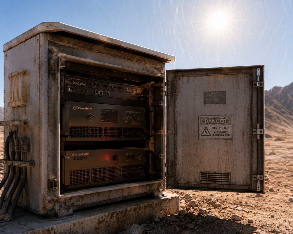
But here is the kicker regarding our purpose-built CorelixRF architecture. We designed the CRF-PA-6000M18000M-200W specifically expecting brutal environmental abuse. Occupying a substantial nineteen-inch, six-U form factor weighing seventy kilograms, this amplifier utilizes massive thermal spreaders directly bonded beneath active devices. We integrated specialized forced air cooling channels pushing massive cubic feet per minute directly across deep-finned sinks. This mechanical approach guarantees core temperatures remain stable even while pushing two hundred watts continuous RF output. Our hardware-level protection circuitry operates independently from software loops, instituting an absolute shut-off alarm threshold exactly at seventy-five degrees Celsius. This prevents cascading failures before they begin. Furthermore, strict component selection ensures stable fifty-three decibel gain regardless of surrounding ambient conditions. We built this unit acting as an immovable physical anchor against thermal chaos, eliminating unpredictable gain droops completely.
CorelixRF Thermal Features
| Feature | CRF-PA-6000M18000M-200W Spec | Engineering Benefit |
| Weight & Size | 70kg, 19″, 6U | Massive thermal absorption capacity |
| Cooling Method | Forced air cooling | Active heat extraction from core |
| Temperature Alarm | 75°C threshold | Hardware-level hard cutoff protection |
7. What Role Does Thermal Dissipation Play In RF Flatness?
Subtopics
● Frequency-dependent heat generation
● Maintaining +/- 5dB tolerances
● Transistor biasing under load
Wait, there is more regarding wideband signal integrity under severe stress. Maintaining power gain flatness across a massive twelve-gigahertz bandwidth requires extraordinary thermal discipline. Amplifying lower frequencies generates vastly different thermal profiles compared pushing signals near eighteen gigahertz. If internal heat sinks warp even slightly, bias currents fluctuate wildly, destroying your specified plus-minus five decibel flatness. Temperature directly alters parasitic capacitances within transistor matching networks. Without uniform heat extraction, high-frequency performance falls off a cliff rapidly. We engineered internal airflow paths ensuring equal cooling distribution across every single transistor package. This precise thermal management allows our unit deliver forty-seven decibel-milliwatt P1dB output consistently without sagging. When you run multi-carrier signals through poorly cooled modules, intermodulation distortion spikes drastically. Our rigorous thermal routing guarantees spurious emissions remain locked down below minus sixty decibels relative carrier, ensuring pristine signal quality during extended operations.
8. How Do You Test The 6-18GHz Amplifier In Harsh Conditions?
Subtopics
● Simulating full load in test chambers
● Monitoring harmonic variations
● Verifying continuous operation
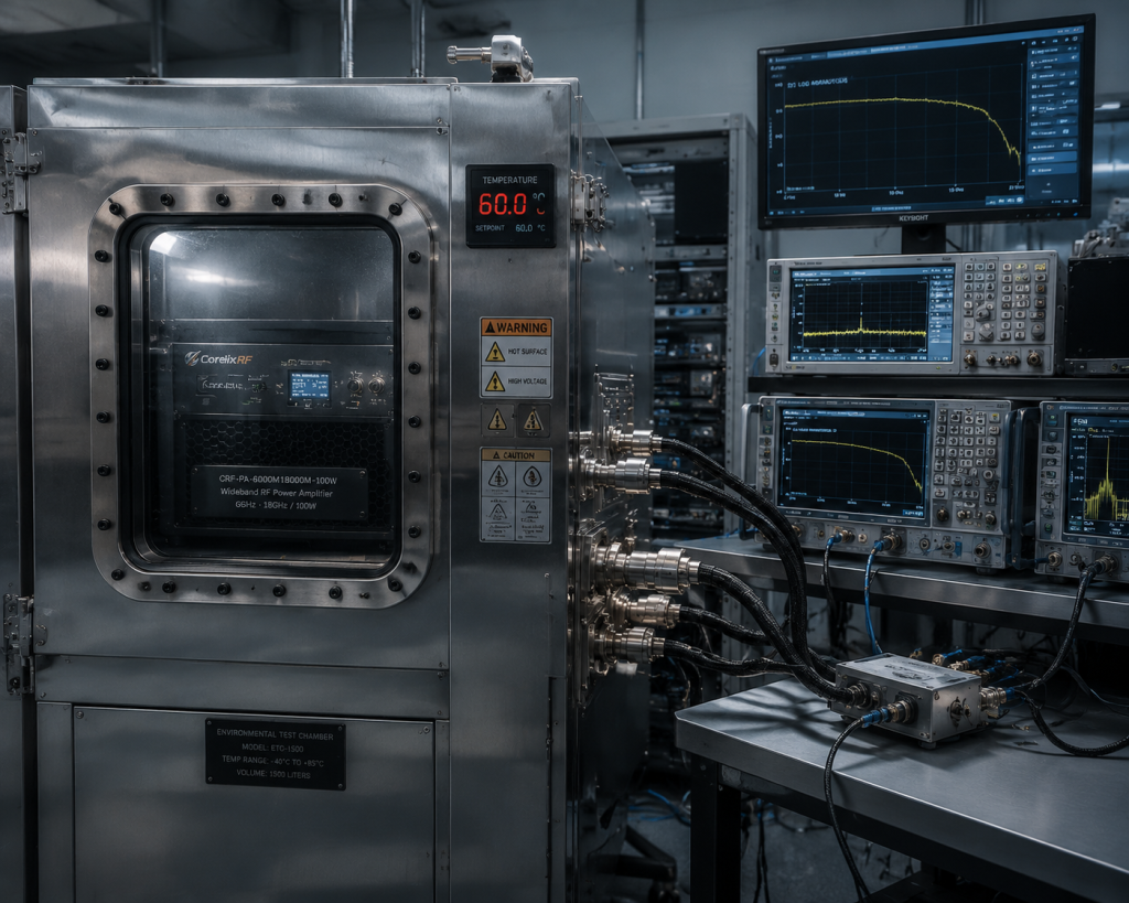
Let me explain our brutal factory validation process before shipping any unit out. We do not just power things up on a clean bench. We force these amplifiers into dedicated environmental chambers simulating hostile realities. Technicians push continuous zero decibel-milliwatt input drive while baking the entire seventy-kilogram chassis. We monitor RS485 and LAN control interfaces continuously, recording every microscopic fluctuation in forward power. Engineers deliberately restrict airflow mimicking clogged field cabinet filters, ensuring built-in over-temperature alarms trigger exactly at specified limits. We analyze harmonic content rigorously, verifying minus fifteen decibels on second harmonics even under severe thermal duress. If an amplifier cannot survive artificial summer conditions while dumping two hundred watts into dummy loads, it never leaves our facility. Real verification requires stressing physical limits until protection circuits engage automatically. This ruthless testing methodology guarantees survival when you integrate hardware into remote radar nodes.
RF Performance Metrics Under Stress
| Parameter | Specification Limit | Field Consequence if Failed |
| Output P1dB | 47 dBm | Signal compression and severe distortion |
| Harmonics | -15 / -8 dBc | Interference with adjacent communication bands |
| Spurious | -60 dBc | Regulatory violations and receiver blinding |
9. What Protection Mechanisms Prevent Total System Failure?
Subtopics
● Fast-acting VSWR cutoffs
● Current limiting circuits
● Over-drive hardware limits
Ready for the good part? Our comprehensive internal defense matrix operates faster than any human operator could ever react manually. We embedded dedicated analog comparators monitoring forward and reflected voltages simultaneously. Should antenna icing cause sudden impedance mismatches, our five-to-one VSWR alarm threshold activates instantaneously. This action drops bias voltages before reflected energy destroys delicate semiconductor structures. Beyond thermal safeguards, we include over-voltage and over-current protection directly tied into heavy-duty solid-state relays. If an upstream synthesizer malfunctions, sending massive input spikes, over-drive limiters clamp down hard. The four-pin aviation plug securing two-hundred-twenty volt AC mains power ensures vibration cannot cause intermittent supply drops. Intermittent drops often generate destructive high-voltage transients damaging primary amplification stages. These redundant boundaries serve as your ultimate insurance policy. We built an electronic fortress around sensitive RF pathways, ensuring catastrophic external events cannot breach internal core components.
10. How Can Integrators Validate The CRF-PA-6000M18000M-200W?
Subtopics
● Benchmarking baseline parameters
● Utilizing provided pattern files
● Monitoring via LAN interface
Think about it from a system architect perspective designing reliable platforms. Validating massive power modules requires structured, methodical approaches before final field deployment. I advise all integrators start by mapping baseline parameters using our supplied test data and pattern files. Hook your analyzer into the SMA-F coupling port, injecting swept frequencies from six through eighteen gigahertz. Monitor real-time telemetry via LAN control interfaces, tracking internal temperature rise against measured power consumption. You should observe exactly four thousand watts maximum draw under full load. Stress test protection limits deliberately using known mismatched loads on a controlled bench setup. Verify that our WRD650 output interface mates perfectly without causing localized heating during continuous wave drive. By reproducing our factory acceptance tests locally, you gain total confidence regarding long-term reliability. Proper upfront characterization eliminates nasty surprises once equipment gets bolted into remote, inaccessible passive nodes.
System Integration Verification
| Action Item | Recommended Tool | Success Criteria |
| Verify Power Draw | AC Power Analyzer | Consumption steady near 4000W under full load |
| Test Control Comms | Laptop via LAN/RS485 | Flawless telemetry reading and command execution |
| Check Coupling Port | Spectrum Analyzer | Accurate forward power representation via SMA-F |
To summarize these unyielding engineering realities, surviving hostile passive node environments demands uncompromising physical hardware architecture. The CorelixRF CRF-PA-6000M18000M-200W eliminates catastrophic gain drift through massive thermal capacity alongside precise hardware-level protection matrices. Stop trusting delicate commercial gear under brutal field conditions; upgrade your infrastructure using proven industrial-grade microwave solutions designed for absolute survival.
FAQ Section
- Q1: What is thermal gain drift in passive nodes?It refers to drastic RF power output reduction caused when trapped ambient heat severely alters semiconductor transconductance properties.
- Q2: How does the CRF-PA-6000M18000M-200W handle heat?This specific amplifier utilizes seventy kilograms of mass alongside redundant forced air cooling channels pushing heat away from active junctions.
- Q3: Why do commercial amplifiers fail at 60°C?They lack sufficient thermal sink mass and rely upon slow software-based protection loops instead of immediate hard hardware cutoffs.
- Q4: How do you troubleshoot field power drops?Engineers should immediately deploy directional power meters and thermal imaging cameras to measure raw physical hardware limits directly.
- Q5: What are the VSWR alarm thresholds for this unit?The hardware protection triggers an absolute shut-off instantly when reflected RF energy exceeds a strict five-to-one standing wave ratio.
Convert 200W gain drift into a thermal acceptance target
For 200W amplifier projects, define duty cycle, ambient temperature, heatsink or airflow, thermal soak duration, allowed gain drift and alarm behavior. These details decide whether the platform needs thermal customization.
Recommended next step: send the operating band, output power target, duty cycle, load condition, control interface, grounding or thermal limits and required FAT documents. CorelixRF can review this 200W RF amplifier thermal gain drift requirement against standard RF amplifier platforms, RF front-end options and controlled customization paths.