
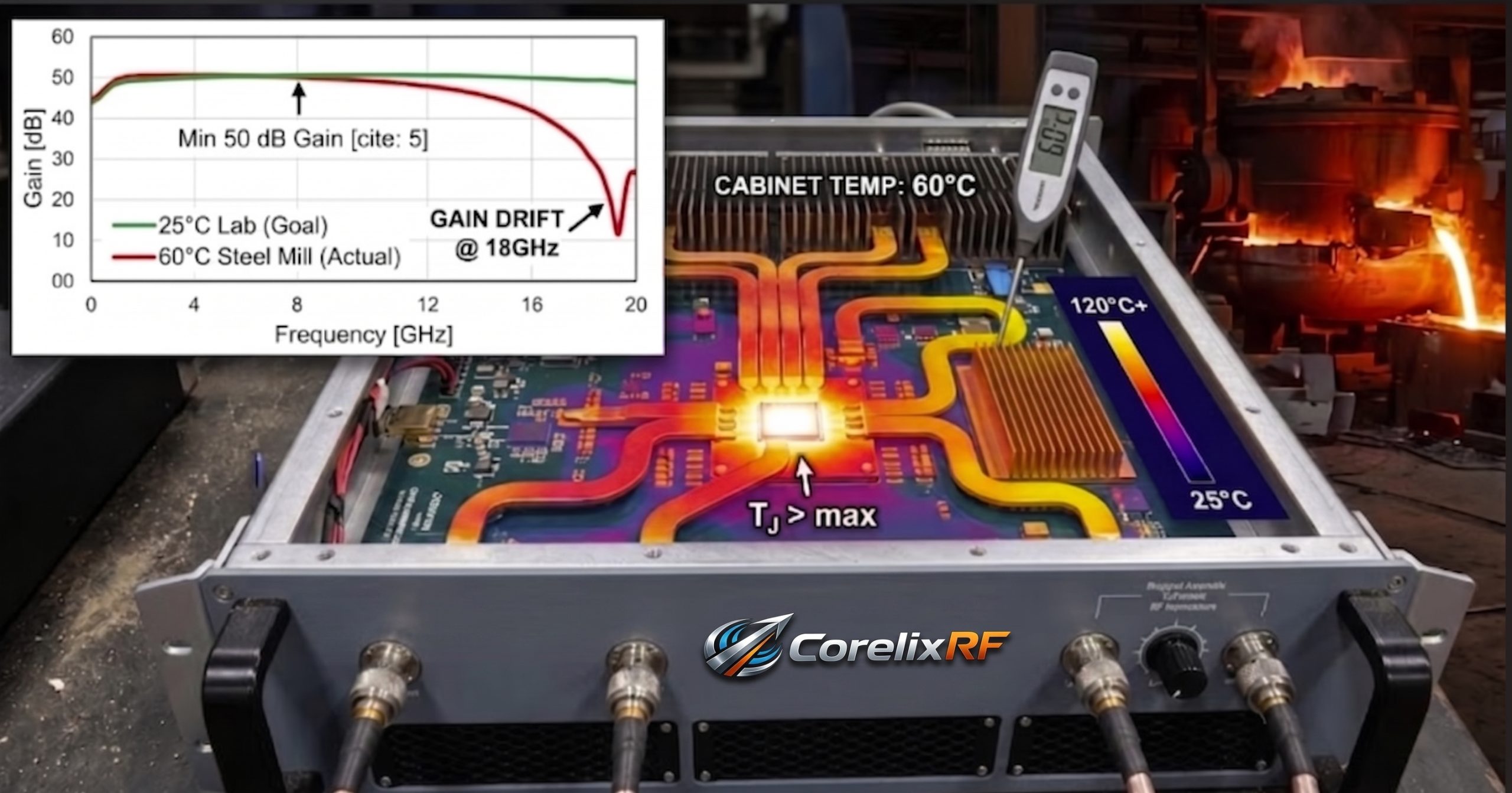
The harsh environment of heavy industry heavily degrades wireless telemetry hardware. We constantly observe critical signal anomalies occurring near active electric arc furnaces. Our goal involves analyzing the specific physical mechanisms causing these frustrating failures.
The Harsh Reality of the Steel Mill Environment
Field Reality Check
A steel mill floor presents an unforgiving RF reality. Your telemetry link drops abruptly near an active electric arc furnace. A control screen flashes continuous standing wave ratio alarms. Output power plummets unexpectedly during critical melt phases. You might be wondering, what causes this specific failure mode? Lab tests conducted at a comfortable 25℃ showed perfect 50 dB small signal gain. Field cabinets often reach a punishing 60℃ ambient temperature near molten metal. That massive thermal delta destroys system margins rapidly. We frequently see engineers misdiagnose this as basic component failure. Technicians often swap coaxial cables unnecessarily. The real culprit involves fundamental thermal gain drift across active semiconductor junctions. High heat alters electron mobility within transistor structures directly. This alters your amplifier operating point significantly. Let us examine this physical mechanism without marketing noise.
Operating Environment Comparison
| Parameter | Laboratory Condition | Steel Mill Field Condition | Impact on RF Hardware |
| Ambient Temperature | 25℃ | 60℃ | Severe thermal gain drift |
| Electromagnetic Interference | Low | Extreme (Arc Furnaces) | Raised noise floor |
| Physical Vibration | Minimal | High continuous | Connector fatigue |
Understanding Thermal Gain Drift in RF Amplifiers
The Physics of Heat
RF power amplifiers behave differently under extreme thermal stress. Gallium Nitride devices experience reduced carrier mobility when junction temperatures spike. This directly reduces raw amplification capability across broadband frequencies. A module delivering 80 W rated output power at room temperature might struggle outdoors. Here is the deal: heat dissipation dictates sustained performance. Our lab records show specific gain flatness characteristics of ±5 dB. This metric assumes controlled environmental conditions. When a field cabinet hits 60℃, internal component temperatures climb much higher. The cascading effect shrinks dynamic range significantly. System integrators must account for this derating during initial link budget calculations. Failing at this design stage guarantees on-site failures. We routinely measure spectrum analyzer traces showing collapsed high-frequency response curves. You cannot fix thermal physics with software patches. Robust hardware engineering remains your only defense against these harsh industrial realities.
Field Diagnostics and Troubleshooting Steps
Instrument Deployment Tactics
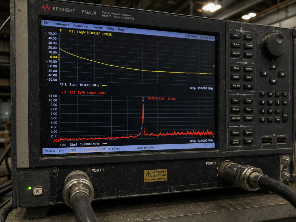
Effective field troubleshooting requires precise instrument deployment. You need a reliable Vector Network Analyzer and a directional coupler. First, measure your forward power entering the antenna subsystem. What is the real story? A high VSWR alarm often indicates thermal expansion affecting coaxial mating surfaces. The factory specified input VSWR sits at 2.0:1. Heat can warp standard dielectric materials causing severe impedance mismatches. Next, evaluate the noise floor using a spectrum analyzer. You should observe levels around -35 dBm/MHz under normal operations. If the baseline elevates dramatically, suspect severe gain compression caused by inadequate cooling. Check the built-in control interface for diagnostic readouts. Our modules utilize RS485 / LAN connections for monitoring. Retrieve internal temperature telemetry directly from the amplifier logic board. Compare this data against your external cabinet ambient readings.
Field Diagnostic Checklist
| Instrument | Measurement Target | Expected Baseline | Anomaly Indicator |
| Vector Network Analyzer | Input VSWR | 2.0:1 | Spikes above 2.5:1 |
| Spectrum Analyzer | Noise Floor | -35 dBm/MHz | Elevated baseline levels |
| Directional Coupler | Output Power | 80 W | Sudden power drops |
The CorelixRF Hardware Solution: CRF-PA-6000M18000M-80W
Advanced Component Engineering
We engineered a specific answer for these brutal industrial environments. The CRF-PA-6000M18000M-80W wideband RF power amplifier operates across 6 – 18 GHz. This unit tackles severe thermal and electromagnetic challenges head-on. This is where it gets interesting: we rely on advanced GaN technology for superior efficiency. High electron mobility transistors handle elevated junction temperatures better than legacy silicon options. The factory datasheet specifies an operating temperature range of 0 to 50℃. When your external cabinet reaches 60℃, forced air cooling combined with massive heat sinks becomes mandatory. We designed the internal thermal pathways utilizing high-conductivity copper carriers. This pulls heat rapidly away from active die surfaces. Spurious emissions remain suppressed at -60 dBc even under heavy load. We focus on engineering truth rather than theoretical best-case scenarios.
CRF-PA-6000M18000M-80W Key Specifications
| Parameter | Specification | Note |
| Frequency Range | 6 – 18 GHz | Broadband coverage |
| Rated Output Power | 80 W | Continuous wave |
| Small Signal Gain | 50 dB | Minimum value |
| Adjustable Gain | 20 dB | Maximum value |
Power Supply and VSWR Protection Mechanisms
Defensive Hardware Architecture
Steel mills suffer from notoriously unstable electrical grids. Heavy machinery drawing massive currents creates severe voltage sags. Our design incorporates a robust AC 220V±10%, 50/60Hz power supply. This isolated conditioning circuit protects sensitive RF components from destructive transients. Ready for the good part? We integrated comprehensive built-in protection mechanisms. These cover over-voltage, over-temperature, over-drive and VSWR conditions. If an antenna gets crushed by falling debris, reflected energy will not destroy the final amplification stage. The system detects the mismatch instantly. It initiates an automatic shutdown sequence immediately. This prevents catastrophic cascading failures across your expensive test and measurement infrastructure. We engineered these defenses based on decades of real-world field failures. You cannot afford downtime during an active steel pour. Hardware must protect itself autonomously without requiring human intervention.
Integrating the 19-inch 3U Chassis
Mechanical Integration Strategies
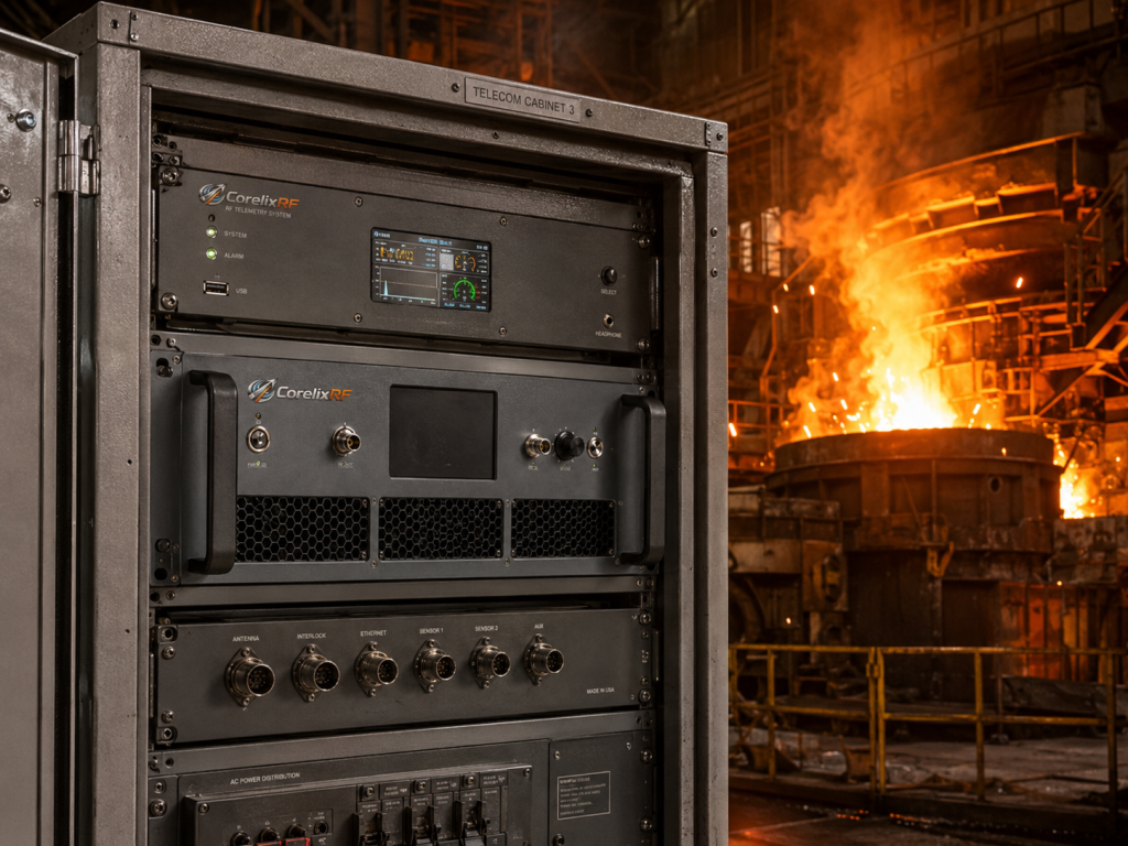
Mechanical design plays a critical role in thermal management strategies. The CRF-PA-6000M18000M-80W utilizes a standard 19-inch, 3U package size. This form factor allows seamless integration into standard industrial equipment racks. Let us dig deeper: adequate spacing prevents heat pooling. We specify an active air cooling method requiring clear intake and exhaust paths. Do not block the front panel vents. A mechanical drawing is provided for clear installation reference. Proper rack placement ensures internal fans can exhaust thermal loads efficiently. We utilize rugged N-F type RF connectors for both input and output. These provide excellent mechanical stability against constant mill vibrations. Secure all mating cables using properly torqued connections. Loose fittings will generate passive intermodulation under high power loads.
Mechanical and Interface Specifications
| Feature | Specification | Integration Note |
| Dimensions | 19″, 3U | Standard rack mount |
| Cooling Method | Air cooling | Maintain clear airflow |
| RF Connectors In/Out | Input: N-F / Output: N-F | Torque appropriately |
| Control Interface | RS485 / LAN | Remote telemetry access |
Evaluating Output Power and Gain Metrics
Dynamic Performance Limits
Understanding dynamic performance metrics prevents poor system integration. The amplifier provides an adjustable gain range of 20 dB. This allows engineers precise control over signal levels entering non-linear operating regions. Truth be told, driving an amplifier into heavy saturation generates severe harmonics. Our units maintain harmonics between -15 and -8 dBc under rated conditions. You must monitor input power carefully during operation. The maximum specified input power equals 0 dBm. Exceeding this threshold triggers the overdrive protection circuitry. Applications involving aviation control or communication demand strict spectral purity. Steel mill environments often hide spurious emissions beneath massive broadband noise floors. CorelixRF guarantees these specifications through rigorous factory acceptance testing before shipment. We rely on hard data rather than theoretical approximations.
Performance Limit Parameters
| Specification | Maximum Value | Consequence of Exceeding |
| Input Power | 0 dBm | Overdrive protection triggers |
| Harmonics | -8 dBc | Signal distortion |
| Spurious | -60 dBc | Spectrum contamination |
| Operating Temp | 50℃ | Thermal protection shutdown |
Customization and Compliance Standards
Industrial Quality Assurance
Industrial clients often require specific hardware modifications. We offer customization options including forward/reverse power monitoring, GPIB control interfaces and input power detection. These features enhance remote diagnostic capabilities significantly. Here is the kicker: factory certifications matter deeply. CorelixRF operates under a strict quality framework. Our products are RoHS Compliant, CE / FCC certified, and manufactured under ISO 9001 and GJB 9001C standards. This ensures every unit performs identically across multiple production batches. Test data and pattern files can be supplied for project review where applicable. We understand that defense contractors and heavy industry integrators require exhaustive documentation. You cannot deploy untested hardware into critical infrastructure environments. Our engineering teams stand behind every shipped module with complete transparency.
Addressing Application-Specific Challenges
Reliability Across Domains
Steel mills represent just one extreme operational environment. We see similar thermal and vibration challenges in electronic warfare and radar systems. The fundamental physics remain identical across these applications. You might be wondering, how do we guarantee longevity? We select components featuring high mean time between failures. Our GaN architecture handles peak-to-average power ratios exceptionally well. This makes the amplifier suitable for complex modulation schemes used in modern communications. Interference applications require continuous wave delivery without unexpected power droop. We design our bias circuits to compensate for minor temperature variations automatically. This maintains a stable operating point even when ambient temperatures fluctuate wildly. Solid engineering principles dictate every design choice we make daily.
Conclusion and System Integration Call to Action
Final Engineering Thoughts
Thermal gain drift destroys RF system reliability in high-temperature environments. We examined the physical mechanisms causing signal anomalies near 60℃ industrial cabinets. Our CRF-PA-6000M18000M-80W amplifier delivers robust 80W performance from 6 to 18 GHz. The bottom line is clear: engineering truth beats generic marketing claims. Evaluate your link budgets carefully before installation. Contact the CorelixRF engineering team today to review test data for your specific integration project.
FAQ
Q1: What is thermal gain drift in RF amplifiers?
Thermal gain drift refers to the unwanted change in amplification performance caused by fluctuating operating temperatures affecting the semiconductor materials.
Q2: How does the built-in VSWR protection work?
The system continuously monitors reflected power at the output port, and it instantly initiates an automatic shutdown if the mismatch exceeds safe operational thresholds.
Q3: Can the CRF-PA-6000M18000M-80W survive ambient temperatures above 50℃? The datasheet specifies an operating temperature up to 50℃; external forced air cooling or cabinet climate control becomes mandatory if the environment reaches 60℃.
Q4: Why do we see elevated noise floors near arc furnaces?
Extreme electromagnetic interference from heavy industrial machinery couples into poorly shielded cables, which raises the baseline noise floor observed on your spectrum analyzer.
Q5: What customization options are available for this unit? Optional features include forward/reverse power monitoring, a GPIB control interface, and input power detection to enhance system integration.
Treat thermal gain drift as a factory-test question
On-site gain drift should be translated into measurable requirements: ambient temperature, operating duty, output power, test duration, gain tolerance, alarm behavior and FAT report format. That gives the factory a clear pass/fail target.
Recommended next step: send the operating band, target output power, duty cycle, thermal or load condition, control interface, protection behavior and required FAT documents. CorelixRF can review this on-site RF amplifier thermal gain drift requirement against standard amplifier platforms, RF front-end options and custom engineering constraints.