
Tracked armor vibration destroys standard radio frequency hardware rapidly. Connector loosening and microscopic joint cracks cause silent system failures. The CRF-PA-300M1700M-50W provides a structurally verified solution for these severe environments. I rely on twenty years of field experience. You must trust proven engineering truth.
1. What Causes Sudden VSWR Alarms Inside Tracked Armor Vehicles?
Identifying the Core Symptom
● Intermittent power drops during movement
● VSWR meter fluctuations
● Track rumble frequencies
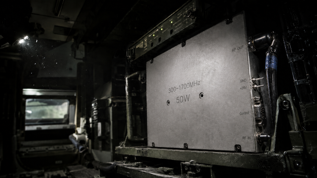
Tracked armor generates severe mechanical rumble continuously. Low-frequency energy transfers directly into mounted electronics. Radio frequency amplifiers experience massive physical stress daily. Connectors vibrate loose over extended operation periods. System screens flash red with reverse power warnings suddenly. Operators lose communication capabilities without any prior warnings. What happens next? Engineers connect portable meters searching for immediate faults. Reflected power spikes indicate severe impedance mismatches clearly. Our field team sees this specific failure repeatedly. Military platforms demand extreme hardware reliability from suppliers. A loose N-Type connector ruins mission effectiveness completely. You cannot fix bad mechanical design with software updates. You must address physical realities immediately during deployment. I have spent two decades troubleshooting these exact failures. RF energy requires perfect physical continuity for transmission. Any gap causes immediate signal degradation across bands. We must examine mechanical resonance profiles carefully onsite. Vehicle tracks produce specific vibration signatures constantly. These frequencies target weak solder joints perfectly every time. This mechanical energy destroys standard commercial amplifiers quickly.
2. Why Do Standard RF Connectors Fail Under Low-Frequency Stress?
Connector Degradation Mechanics
● Thread degradation over time
● Impedance mismatch introduction
● N-Female and SMA vulnerability analysis
Threads on standard SMA connectors wear down rapidly outdoors. Continuous shaking acts like abrasive paper on metal. Metal surfaces grind against each other constantly under armor. Consider this physical reality. A once-tight connection becomes slightly loose eventually. High-frequency signals see this tiny gap as an obstacle. The 300-1,700 MHz band requires tight physical tolerances always. Impedance shifts away from fifty ohms quickly and permanently. Reflected energy returns back towards the main power transistor. Heat builds up inside the sealed amplifier housing. N-Female connectors on output ports suffer similar violent fates. Their larger mass makes them susceptible to low-frequency shaking. Tracked vehicles operate around ten hertz naturally during patrols. This specific frequency matches many chassis resonance points perfectly. Commercial connectors lack necessary locking mechanisms for survival. Engineers often ignore proper torque wrench procedures onsite. Hand-tightened joints fail within hours during harsh field deployments. We require rigid mounting solutions for reliable continuous operation. Our designs utilize specific thread locking compounds effectively.
Connector Vibration Resilience
| Connector Type | Frequency Response | Failure Mode |
| Standard SMA | 300-1,700 MHz | Thread loosening |
| N-Female | Output stages | Center pin fretting |
| SMA-KFD46 | High stress zones | Resists backing out |
3. How Does Microscopic Solder Joint Cracking Manifest on a VNA?
Tracing S-Parameter Anomalies
● S21 gain degradation
● Phase noise elevation
● High-frequency band collapse
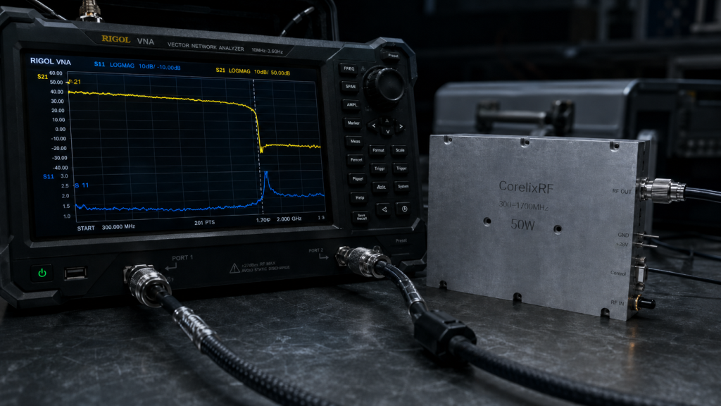
Microscopic cracks form inside internal solder joints silently. Lead-free solder becomes brittle under continuous physical stress. Let that sink in. You connect a Vector Network Analyzer for diagnostic testing. Forward transmission curves show strange anomalies instantly. S21 gain drops below our forty-six decibel minimum limit. The curve collapses completely near the 1,700 MHz edge. This high-frequency collapse indicates severe physical separation inside. Electrons cannot jump across microscopic physical gaps efficiently. Phase noise increases dramatically during heavy vibration events. You observe these fluctuations on spectrum analyzers clearly onsite. System integrators misdiagnose this as normal transistor failure often. They replace expensive components without solving the root causes. A cracked joint creates intermittent electrical contact randomly. Temperature shifts make these cracks expand or contract unpredictably. Cold morning operations might show perfect S-parameters initially. Afternoon heat causes total system failure without warning. You need meticulous inspection protocols for early detection. X-ray imaging reveals these hidden structural flaws definitively.
4. What Instruments Reveal These Hidden Mechanical Failures?
On-Site Diagnostic Tooling
● Using portable network analyzers
● Time-domain reflectometry (TDR)
● Vibration spectrum correlation
Field engineers rely on specific diagnostic tools daily. A portable VNA identifies impedance mismatches quickly and accurately. We utilize Time-Domain Reflectometry techniques regularly for isolation. TDR sends short pulses down the main transmission lines. Reflected signals pinpoint exact fault locations along cables. You might be wondering about this technique. It reveals whether the connector or internal board failed. We attach sensitive accelerometers onto amplifier housings directly. These sensors record actual vibration profiles during combat operation. We correlate electrical failures with mechanical stress events precisely. Oscilloscopes capture fast power dropouts effectively in real time. An output power meter confirms continuous 50 W delivery capabilities. Any sudden dip triggers immediate field investigation protocols. We test input drive levels between 0 and 8 dBm. We verify return loss stays below strict specified limits. The CRF-PA-300M1700M-50W maintains an input VSWR below 1.8:1 consistently. This precise measurement requires calibrated testing equipment always. Proper testing cables eliminate false readings during field evaluations.
Diagnostic Equipment Parameters
| Instrument | Target Measurement | Expected Value |
| Portable VNA | Input Match (S11) | <= 1.8:1 VSWR |
| Power Meter | Saturated Output | 50 W CW |
| Oscilloscope | Voltage Supply | 28 VDC stable |
5. Why Is Thermal Cycling Exacerbating Mechanical Vibration Damage?
Thermomechanical Stress Factors
● Expansion coefficient mismatch
● Heat dissipation under armor
● Solder fatigue acceleration
Heat creates major problems inside enclosed metal spaces. Armored vehicles lack proper airflow for mounted electronics. Internal temperatures rise rapidly during continuous transmitter operation. Here is a known fact. Different component materials expand at completely different rates. Copper expands faster than specialized ceramic board substrates. This coefficient mismatch tears solder joints apart mechanically. You combine this thermal expansion with violent physical shaking. Joint fatigue accelerates exponentially under these extreme dual stresses. The required cooling method demands careful engineering thought. Our modules utilize specialized external air cooling fins. Operating temperatures range from -40 °C up to +85 °C. Transistors draw nearly 7 A of current continuously. This high power dissipates significant heat into the baseplate. Poor thermal management melts weak solder connections eventually. We conduct extensive thermal shock testing internally before shipping. Modules cycle between temperature extremes repeatedly during qualification. We guarantee structural integrity before any final field deployment.
6. How Can System Integrators Quantify RF Power Degradation?
Measuring Output Power Loss
● 50W CW output stability
● Current consumption monitoring
● Recognizing the <= 7 A threshold
Measuring raw output power reveals hidden system problems quickly. An amplifier must deliver 50 W continuously without dropping. Any drop below this rating indicates internal structural damage. System integrators must monitor input current consumption constantly. Take note of this detail. A healthy operational unit draws 7 A maximum. Current spikes suggest severe output impedance mismatches immediately. Dropouts in current indicate physical open circuits internally. We run Continuous Wave signals for thorough field verification. Saturated power output remains stable across all tested frequencies. A spectrum analyzer verifies harmonic content during full operation. Harmonics must stay below -10 dBc relative to carrier. Spurious emissions need strict containment below -60 dBc. Bad solder joints generate terrible intermodulation distortion rapidly. This distortion destroys sensitive communication link margins entirely. You lose critical data packets due to poor signal quality. Quantifying these exact metrics proves hardware reliability objectively.
Electrical Performance Verification
| Parameter | Specification | Test Condition |
| Output Power | 50 W | CW / Saturated |
| Harmonics | <= -10 dBc | Full power |
| Spurious | <= -60 dBc | 300-1,700 MHz |
7. What Makes the CRF-PA-300M1700M-50W Structurally Superior?
Engineering a Robust Enclosure
● 125 x 59 x 21.5 mm form factor rigidity ● SMA-KFD46 mounting techniques ● Mass reduction (<= 0.5 kg) benefits
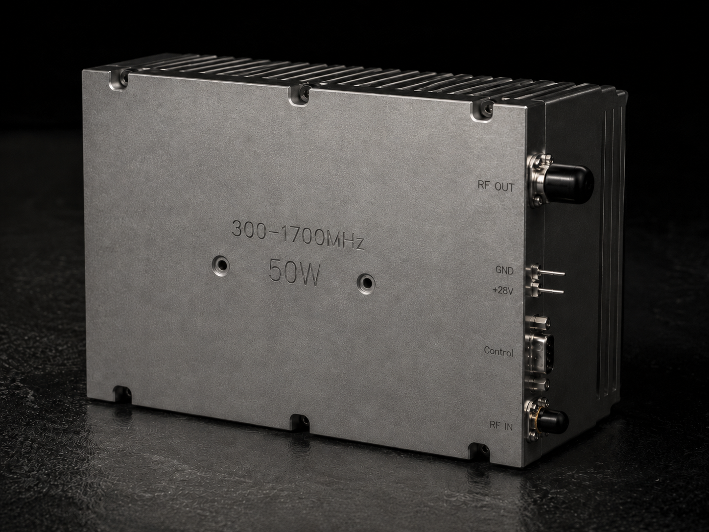
We designed the CRF-PA-300M1700M-50W specifically for extremely harsh environments. The precision housing measures exactly 125 x 59 x 21.5 mm. This compact size reduces dangerous mechanical resonance significantly. Here is where things get serious. A physically smaller mass vibrates much less violently. The total operational weight stays below 0.5 kg. This low mass puts less stress on securing mounting bolts. We utilize specific SMA-KFD46 input connectors for durability. These connectors flange mount directly into our machined chassis. This technique prevents rotational forces from breaking delicate internal pins. The DB9 control interface features secure mechanical locking screws. Our factory machines each aluminum housing from solid metal blocks. We avoid cheap cast metal completely for military applications. The N-Female output connector integrates seamlessly with thick metal walls. We use specialized thread locking compounds during final assembly. The entire amplifier structure acts like a single solid component.
8. How Does Wideband Operation Complicate Troubleshooting?
Covering 300-1,700 MHz Effectively
● Harmonic performance under stress
● Maintaining <= 1.8 dB gain flatness
● Spurious emission containment (<= -60 dBc)
Broadband RF amplifiers present completely unique field diagnostic challenges. Covering 300-1,700 MHz requires highly complex internal matching networks. A physical circuit defect might only affect specific narrow frequencies. Consider this engineering reality. Low frequency signals might pass perfectly through a cracked joint. High frequency waves will reflect backward immediately causing alarms. Gain flatness must remain below 1.8 dB across the band. Vibration damage alters tiny parasitic capacitance values internally. This capacitance shift ruins the carefully tuned flat gain profile. The amplifier typical operational gain sits at 47 dB. Even a small impedance change drops this specific gain drastically. You must sweep the entire frequency band during testing. A single frequency check hides wideband performance degradation completely. We use automated test equipment for thorough production sweeps. The network analyzer plots S21 and S11 graphs simultaneously. We demand complete compliance across every single megahertz tested.
Broadband Gain Characteristics
| Metric | Min | Typ | Max |
| Gain (dB) | 46 | 47 | 48 |
| Flatness (dB) | – | – | <= 1.8 |
| Freq Range | 300 MHz | – | 1,700 MHz |
9. What Mitigation Strategies Prevent Future Solder Fractures?
Advanced Manufacturing Processes
● Rigid PCB substrate selection
● Optimized reflow profiles
● Connector strain relief implementation
Preventing structural fractures starts during the initial manufacturing phase. We select ultra-rigid printed circuit board substrates purposely. These specialized materials resist bending under extreme mechanical stress. Here is the bottom line. We profile our factory soldering ovens meticulously daily. Perfect reflow temperatures create strong reliable intermetallic bonds. We inspect every critical solder joint using advanced optical microscopes. The factory applies custom strain relief directly onto sensitive components. We pot certain vulnerable sections using specialized damping compounds. This compound absorbs destructive low-frequency kinetic energy effectively. The DB9 control connector receives extra mechanical physical support. We design the internal RF layout to minimize vulnerable trace lengths. Our thirty years of factory manufacturing experience dictates these rules. We control every single production variable strictly onsite. We reject any circuit board showing microscopic solder voiding. You cannot fake true engineering reliability in tracked vehicle applications.
10. How Should R&D Engineers Evaluate Amplifiers for Military Platforms?
Establishing Validation Protocols
● Long-duration vibration testing
● Input drive (0-8 dBm) verification
● Environmental compliance standards
Proper module evaluation requires brutal physical testing protocols always. Engineers must bolt the amplifier onto a mechanical shaker table. We run random vibration profiles simulating actual tracked vehicle movement. This is standard procedure. We monitor continuous output power during violent shaking tests. The required input drive stays between 0 and 8 dBm. Any power fluctuation constitutes a total catastrophic test failure. We review electrical compliance against strict military quality frameworks. The CRF-PA-300M1700M-50W meets demanding armored operational requirements perfectly. You must check DC current draw stability under extreme stress. The <= 7 A limit acts as a hard protective boundary. We provide complete environmental validation data for formal project reviews. CorelixRF factory engineers supply custom feasibility reviews within forty-eight hours. You need solid measured data before integrating any RF module. Field failures cost lives and ruin supplier engineering reputations. Trust physical hardware testing over glossy paper specifications always.
Compliance and Review Standards
| Framework | Status | Application |
| ISO 9001 | Certified | Factory Quality |
| RoHS | Compliant | Material Standard |
| Validation | Available | System Review |
Tracked armor vibration destroys standard radio frequency hardware rapidly. Connector loosening and microscopic joint cracks cause silent system failures. The CRF-PA-300M1700M-50W provides a structurally verified 50 W solution for these severe environments. You must demand rigorous physical validation for military communication platforms. Contact the CorelixRF engineering team today for detailed S-parameter data. We support your system integration with uncompromising technical truth.
FAQ
Q1: What causes sudden VSWR alarms inside tracked vehicles?
Low-frequency mechanical vibration loosens RF connectors and cracks internal solder joints, causing immediate impedance mismatches.
Q2: How does the CRF-PA-300M1700M-50W handle vibration? It uses a compact 125 x 59 x 21.5 mm rigid chassis , flanged SMA-KFD46 connectors , and weighs under 0.5 kg to minimize resonance.
Q3: What is the maximum current consumption for this module? The amplifier draws a maximum of 7 A from a 28 VDC supply while delivering 50 W CW output power.
Q4: How do engineers detect microscopic solder cracks? Engineers use portable Vector Network Analyzers to sweep the 300-1,700 MHz band, looking for S21 gain drops or S11 VSWR spikes.
Q5: What input drive level is required for rated output? The amplifier requires an input drive level between 0 and 8 dBm to achieve the full 50 W saturated output power.
Authorized RF engineering and compliance review
For regulated RF systems, this page should be used as an engineering and compliance review path, not as a public deployment checklist. CorelixRF starts with authorization status, operating region, frequency plan, output limit, antenna interface, safety controls, thermal limits and acceptance documents.
- RFQ checklist – send the data buyers usually forget, including band, power, duty cycle, interface and test standard
- delivery documentation – check what documents can support incoming inspection, FAT review and long-term maintenance
- quality and certification review – review the quality and compliance evidence before the project moves into procurement
- RF front-end platform – compare the RF chain as a system instead of selecting one isolated module
- RF configurator – turn frequency, power, thermal and interface requirements into a first configuration brief
- case studies – review similar engineering paths before sending an RFQ
- engineering contact – send the application notes, block diagram or target specification to engineering sales
This keeps the discussion inside lawful, authorized RF programs while still giving procurement teams a clear way to request amplifier, antenna, SDR source, documentation and factory review.