
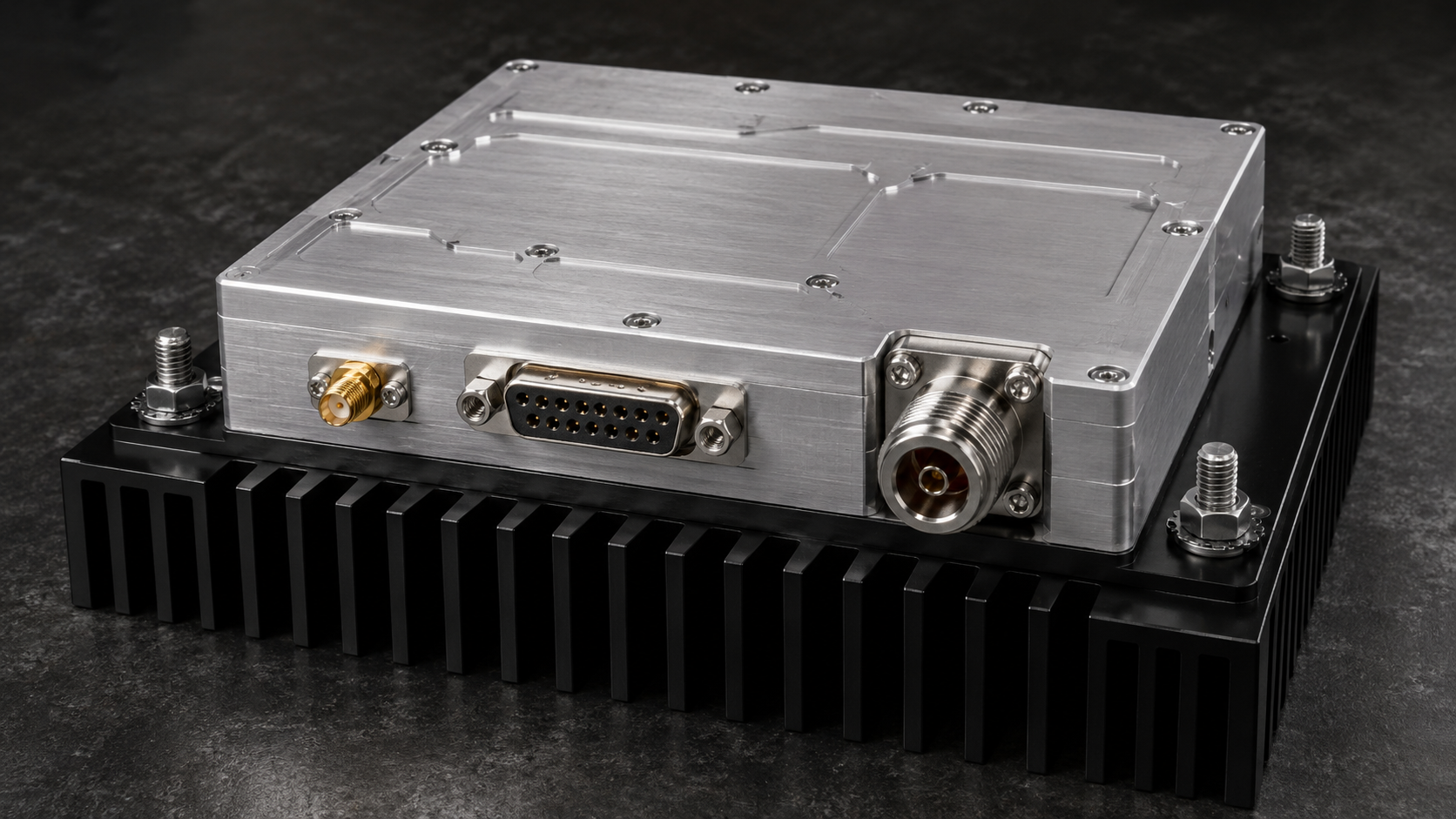
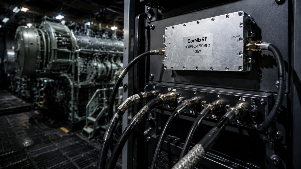
We frequently adapt this diagnostic framework for a harsher environment: naval vessel engine rooms. High-level mechanical shaking tears apart poorly manufactured electronics leaving combat systems blind. We deploy the CRF-PA-300M1200M-100W rugged hardware featuring strict tolerance limits solving these exact failures. CorelixRF manufactures these exact solutions daily carrying thirty years of factory-level manufacturing experience backing our designs. Here’s the deal: standard commercial gear crumbles under marine propulsion stress. I will show you how our team diagnoses these hidden faults effectively. We will review specific benchtop testing procedures together. You need factual engineering data for survival.
1. Why Do RF Signals Degrade Inside A Naval Vessel Engine Room?
Naval propulsion compartments generate relentless mechanical energy. Diesel generators produce continuous structural resonance. This shaking transfers directly into electronic racks. Frequencies typically hover between ten and fifty hertz. You might be wondering: why do thick metal enclosures fail? Metal shields cannot stop kinetic energy transfer. Kinetic energy travels through mounting rails directly into your RF amplifier chassis. SMA connectors experience severe sheer force. Coaxial cables whip around violently without proper strain relief. Dielectric materials inside these cables deform over months of deployment. Changes in dielectric spacing alter characteristic impedance. Impedance shifts cause immediate signal reflection. Reflected power returns straight into your driver stage. I have seen countless screens flash red warning lights during sea trials. VNA sweeps often show chaotic return loss spikes during live engine tests. Technicians initially blame bad cables. They swap cables but issues persist. We always look deeper at component-level fatigue. Commercial off-the-shelf devices simply lack adequate structural reinforcement. You need purpose-built hardware for these zones. I remember one specific frigate losing radar capabilities unexpectedly. They blamed software glitches initially. Our team measured physical displacement reaching three millimeters peak-to-peak. This extreme motion stressed every single hardline connection point. We discovered snapped center pins inside their primary distribution manifold. The physics remain simple yet brutal. Massive diesel blocks displace air and steel equally. Electronic components absorb this energy unless isolated perfectly. Poorly designed mounts amplify specific resonant frequencies destructively.
Environmental Factors
| Parameter | Typical Value | Impact on RF |
| Vibration Frequency | 10–50 Hz | Connector sheer force |
| Acceleration | 2–5 G | PCB flexure |
| Operating Ambient | -40 to +60 °C | Thermal expansion |
2. How Do Low-Frequency Vibrations Destroy Standard Solder Joints?
Micro-cracking represents our most elusive enemy on board. Standard tin-lead or basic lead-free solder becomes brittle under continuous flexing. PCB substrates bend microscopically during hull vibrations. Rigid surface-mount components fight against this bending motion. Shear stress concentrates right at component termination pads. What’s the real story? Hairline fractures develop over several months of operation. These cracks remain completely invisible under normal visual inspection. Electrical continuity might even measure perfectly fine when engines remain silent. Once massive turbines spool up however everything changes. Vibration forces pull those microscopic fractures apart intermittently. You experience rapid gain fluctuations. Your spectrum analyzer displays an elevated noise floor suddenly. Engineers pull their hair out trying trace these ghost anomalies. I recall one specific defense contractor losing sleep over this exact phenomenon. They replaced antennas amplifiers and power supplies repeatedly. Nobody suspected microscopic fatigue within the final power amplification stage. CorelixRF specifically engineers our internal PCB layouts mitigating flexure risks entirely. We analyzed failed boards under scanning electron microscopes recently. Images revealed massive grain boundary separation within lead-free solder joints. High-stress areas around thick copper pours failed first. Thermal mass differences during wave soldering created initial weaknesses. Mechanical vibration simply finished the job. Solder joints literally shattered like glass under microscopic observation. We train our factory technicians recognizing these high-stress layouts. We reposition heavy components away from board centers. We add mechanical screw tie-downs near large inductors. We utilize flexible PCB substrates when extreme flexing becomes unavoidable.
3. What Instrumentation Methods Reveal Hidden Micro-Cracks?
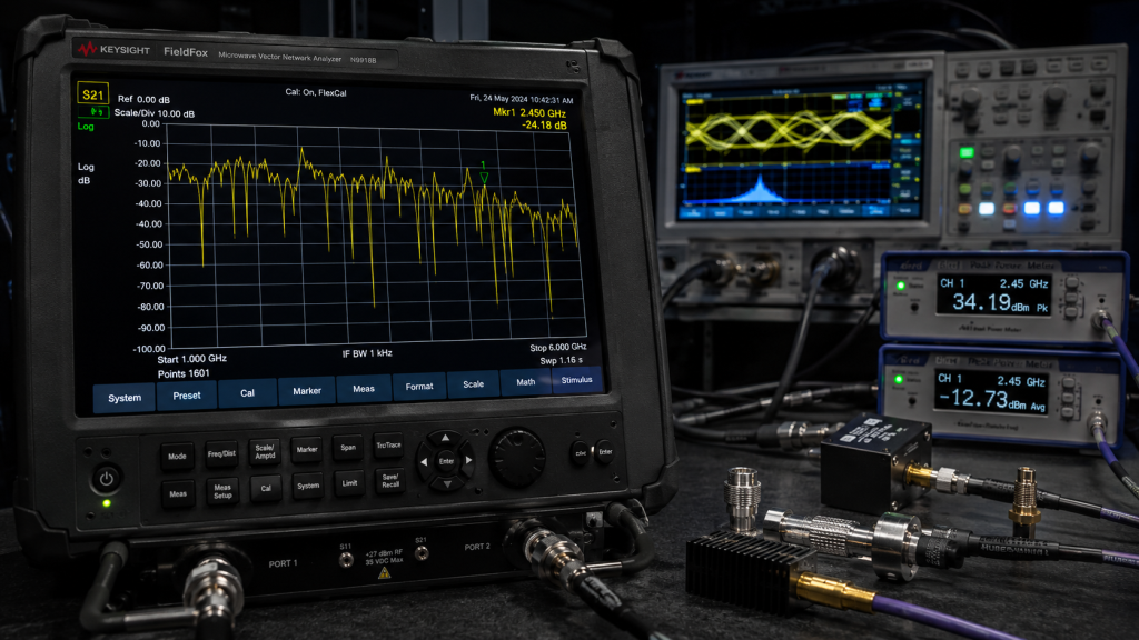
Proper field diagnosis requires specific test equipment. You can’t rely on basic multimeters. Multimeters sample too slowly for intermittent breaks. We utilize high-speed digital storage oscilloscopes primarily. Connect an oscilloscope across your DC supply rails. Let’s look at the facts: you will often spot sharp voltage transients corresponding with hull vibrations. Next we deploy portable Vector Network Analyzers. Hook up your VNA and run a continuous sweep. Tap the amplifier casing lightly using a non-metallic tool. Watch your S21 transmission curve carefully. Sudden drops indicate mechanical separation happening internally. We also monitor forward and reverse power simultaneously. A directional coupler feeds signals into fast-responding peak power meters. If reverse power jumps randomly while forward power drops you found trouble. This confirms an impedance mismatch occurring downstream from your active devices. I spent three weeks off the coast doing exactly this testing. We documented specific frequency bands triggering structural resonance. Our data proved standard commercial components resonate catastrophically at thirty hertz. We also employ thermal imaging cameras tracking localized heat bursts. A failing solder joint increases electrical resistance sharply. This resistance generates instantaneous heat under high RF power loads. You can actually see tiny bright flashes on thermal screens during vibration cycles. It looks like miniature lightning storms happening across the board. We combine these thermal signatures with our oscilloscope data. This multi-dimensional diagnostic approach leaves no room for guesswork. We pinpoint the exact component failing within minutes. We stop guessing and start engineering real solutions based on raw physical data.
Diagnostic Instrumentation
| Instrument | Purpose | Fault Detection |
| Digital Oscilloscope | Monitor DC rails | Voltage transients |
| Portable VNA | Sweep S21 | Intermittent mechanical separation |
| Peak Power Meter | Measure FWD/REV | Impedance mismatch |
4. Why Does Continuous Salt Fog Exacerbate Impedance Mismatches?
Engine rooms ingest massive amounts of ambient ocean air. Ventilation systems drag corrosive salt mist directly over electronic racks. Salt acts as an aggressive electrolyte. It immediately attacks any exposed metallic surfaces. This is where it gets interesting: micro-cracks from vibration create perfect entry points for corrosion. Saltwater seeps into those microscopic hairline fractures. Galvanic corrosion accelerates rapidly between dissimilar metals on PCB traces. Copper pads oxidize turning green and resistive. Resistance increases exponentially across RF pathways. High power signals hit these resistive joints generating localized heat hotspots. Thermal expansion then widens existing cracks further. It creates a brutal feedback loop destroying hardware fast. Standard nickel-plated connectors tarnish within weeks. RF performance degrades silently until total catastrophic failure occurs. We frequently encounter burned-out boards covered in salty residue. You must utilize conformal coating alongside hermetic sealing techniques. CorelixRF processes guarantee our internal cavities remain completely isolated from corrosive atmospheres. We ran specialized salt fog chamber tests comparing standard parts against ours. Standard commercial amplifiers failed completely within forty-eight hours. Internal short circuits triggered massive current draws melting power supply lines. Our units ran continuously for five hundred hours without dropping one decibel. We apply specialized urethane conformal coatings shielding every exposed trace. We seal external chassis seams utilizing conductive elastomer gaskets. These gaskets provide both environmental sealing and EMI shielding simultaneously. You can’t compromise on environmental protection in marine settings.
5. How Does CorelixRF Address High VSWR Under Extreme Mechanical Stress?
Our factory anticipated these precise environmental hazards. We developed model CRF-PA-300M1200M-100W specifically for brutal deployments. This wideband amplifier covers three hundred through twelve hundred megahertz effortlessly. Ready for the good part? We implemented a robust internal protection architecture. Extreme vibration inevitably causes antenna damage or cable severing. Such events drive VSWR levels dangerously high. A severed cable reflects a full one hundred watts back into our unit. Standard amplifiers would instantly burst into flames. Our proprietary circuit detects reflected power instantaneously. The VA alarm triggers if output ports open or short out. An active five-volt logic signal flags the system controller. Our amplifier shuts down automatically saving internal transistors. We lock this fault status preventing destructive power cycling. You must input an external pulse signal for resetting. This forces technicians out of their chairs. They must physically inspect transmission lines before resuming operation. It saves system integrators thousands of dollars in replacement costs. We tested this protection circuitry hundreds of times intentionally. I personally watched technicians sever live output cables utilizing heavy bolt cutters. The amplifier detected this massive impedance mismatch within microseconds. Output power dropped to zero instantly protecting our expensive laterally diffused metal oxide semiconductor transistors. A red fault LED illuminated confirming safety shutdown. The system operator acknowledged the fault replacing the severed cable safely. They applied a reset pulse restarting the mission instantly. Nobody replaced any burned amplifier modules that day. Real engineering prevents catastrophic downtime.
6. What Are The Electrical Characteristics Of CRF-PA-300M1200M-100W?
Let me share actual production data from our manufacturing floor. We guarantee a saturated output power reaching one hundred watts. Frequency range spans 300 to 1200 MHz seamlessly. Gain sits squarely at 46 dB typical. We maintain excellent gain flatness within plus or minus four decibels. Truth be told: nominal supply voltage requires twenty-eight volts. We accept an input range spanning 24 to 32 VDC. Typical operating current draws 11.5 amperes. Maximum current never exceeds 14 amperes under heavy load. Noise figure remains below twenty decibels. We utilize standard SMA female input connectors. Output relies on rugged N-type female connectors. We suppress second and third harmonics down below minus ten dBc. Spurious emissions stay firmly below minus sixty dBc. Our PA enable time clocks in under ten microseconds. These metrics provide unmatched stability for communication interference applications. We verify every single unit using fifty-ohm bench setups. Our four hundred employees take extreme pride manufacturing reliable RF hardware. We document every performance metric meticulously before shipping anything. Our quality control team runs automated test sequences across all temperatures. We verify gain flatness across the entire band guaranteeing no drop-outs occur. The twenty-eight-volt nominal supply simplifies integration with standard military vehicle power buses. The built-in over-voltage protection catches nasty alternator spikes easily. We design our input matching networks handling up to ten dBm safe input levels. This provides ample headroom avoiding accidental front-end destruction. CorelixRF delivers predictable RF energy reliably.
CRF-PA-300M1200M-100W Electrical Specs
| Parameter | Specification | Note |
| Frequency Range | 300 – 1,200 MHz | Wideband |
| Output Power | 100 W (Psat) | Guaranteed |
| Supply Voltage | 24–32 V | 28 V nominal |
| Operating Current | 11.5 A typ, 14 A max | High efficiency |
7. How Does Real-Time RS485 Monitoring Prevent Catastrophic System Failure?
Blindly operating high-power RF equipment invites disaster. You need constant situational awareness. We integrated comprehensive RS485 serial communication into our D-Sub fifteen-pin interface. Pay attention to this: system controllers poll our amplifier continuously. You receive real-time telemetry regarding operational health. Pin 10 outputs a forward RF power indicator voltage. Pin 7 provides a reversed power indicator analog signal. You can literally watch antenna degradation happening live. A 5V alarm triggers on pin 2 if supply voltage exceeds 32V. Another 5V alarm activates on pin 3 when current surpasses 16A. Pin 12 monitors thermal conditions closely. If internal temperatures exceed eighty degrees Celsius our unit shuts down. Pin 14 outputs an analog voltage directly proportional with temperature. The formula reads: Vmeasured minus zero point five divided by zero point zero one equals Celsius. We hand system integrators total control over their thermal budgets. This proactive monitoring stops catastrophic failures long before they occur. We expose these communication registers documenting every command byte thoroughly. Software engineers love our straightforward hex command structures. You poll register zero getting complete status flags back instantly. A value of zero zero means perfect health. Any bit flipped high indicates specific module distress. We measure temperature directly on the transistor flange maximizing accuracy. We do not guess junction temperatures using ambient air sensors. True engineering requires measuring parameters right at the source. This data feeds directly into ship-wide damage control networks.
D-Sub 15-Pin Interface
| Pin | Function | Description |
| 2 | Voltage Alarm | 5V when > 32V |
| 3 | Current Alarm | 5V when > 16A |
| 7 | Pr Indicator | Reversed RF power (0–3V) |
| 12 | Temp Alarm | 5V when > 80°C |
8. Why Must We Rethink Heat Dissipation In High-Vibration Naval Environments?
Traditional active cooling fans fail miserably aboard ships. Salt fog destroys fan bearings quickly. Vibration shatters cheap plastic fan blades. You must rely purely on conduction cooling. Our module measures 200 by 158 by 25 millimeters. It weighs maximum 1.4 kilograms. Here’s a crazy thought: we designed the entire chassis acting as a massive thermal conduit. You must bolt this flat surface directly against a substantial system heat sink. The chassis material utilizes aerospace-grade aluminum alloy. We specify exact torque requirements for all mounting screws. Uneven mounting creates microscopic air gaps. Air acts as an excellent thermal insulator. Thermal insulators destroy high-power amplifiers. Vibration slowly loosens improper mounting hardware. We recommend thread-locking compounds universally. Our internal layout distributes heat-generating devices evenly. We avoid concentrating thermal loads near sensitive control electronics. Proper thermal management guarantees stable operation between minus forty and plus sixty degrees ambient. Storage temperatures safely reach plus eighty-five degrees. We machine our heatsink mating surfaces perfectly flat guaranteeing maximum contact area. Our engineers specify a surface roughness not exceeding zero point eight micrometers. This mirror-like finish eliminates those microscopic air pockets completely. We also calculate thermal spreading resistance carefully. Heat must travel outward before traveling downward into your system sink. We calculate our baseplate thickness balancing weight against thermal mass effectively. We reject thin flimsy casings outright. Our mechanical outline drawing clearly defines all keep-out zones. We make thermal integration foolproof for external design teams.
9. What Installation Procedures Guarantee Long-Term RF Reliability?
Proper installation dictates survival. I have watched brilliant designs fail because a technician rushed the final assembly. Begin by inspecting your mating surfaces. Wipe down both the amplifier base and system heat sink thoroughly. Apply a highly conductive thermal interface pad. Avoid cheap thermal paste. Thermal paste pumps out during thermal cycling and vibration. Let’s dig deeper: align all mounting holes perfectly before inserting screws. Torque each screw incrementally following a star pattern. This prevents chassis warping. Connect your N-type output cable carefully. Use a calibrated torque wrench for RF connectors. Over-tightening damages dielectric materials. Under-tightening guarantees vibration-induced loosening. Secure your D-Sub control connector using its integrated locking screws. Tie down all cables next utilizing mil-spec strain relief methods. Cables must never hang freely. Free-hanging cables act like pendulums during hull vibrations. These simple procedures eliminate ninety percent of field failures. CorelixRF includes detailed mechanical drawings facilitating flawless integration. We provide torque specifications directly on our mechanical drawings. M4 mounting screws require two point five Newton-meters of torque exactly. SMA connectors need zero point nine Newton-meters strictly. We highly recommend using lock washers universally. Vibration loosens un-locked hardware within hours at sea. We supply comprehensive integration guides covering cable routing paths. You must maintain minimum bend radii preventing coaxial dielectric crushing. A crushed cable creates its own impedance mismatch regardless of amplifier quality. Follow our mechanical guidelines treating them like absolute law.
Installation Torque Specs
| Component | Recommended Torque | Impact of Failure |
| M4 Mounting Screws | 2.5 N-m | Thermal runaway |
| SMA-F Input | 0.9 N-m | VSWR mismatch |
| N-F Output | 1.5 N-m | Arc discharge |
10. How Can System Integrators Verify These Claims During Prototyping?
We encourage rigorous testing. Don’t just read our datasheet. Order a prototype unit. Bolt it onto a vibration table. Replicate your engine room resonance profile. Run a continuous RF signal through it. Monitor output power using the RS485 interface while shaking it. Look at the evidence: we run these exact profiles inside our thirty-year-old factory. We simulate salt fog exposure for hundreds of hours. We short-circuit the output port while pushing one hundred watts. We verify our protection circuits trigger flawlessly every single time. Our engineering team provides feasibility reviews within forty-eight hours. We offer custom frequency bands if needed. We modify control interfaces accommodating legacy systems. System integrators appreciate our objective engineering approach. We focus entirely on delivering measurable performance. We produce hardware that survives. Contact our sales engineers today. Request the complete mechanical outline and test pattern files for your next design review. We ship prototypes containing full factory calibration data sheets. You receive exact S-parameter files confirming our published specifications. We welcome your engineers visiting our four-hundred-person facility. Walk our production lines seeing our quality control firsthand. We build our own testing jigs guaranteeing absolute consistency. We employ network analyzers from top-tier brands guaranteeing measurement accuracy. Don’t gamble your naval contracts on unverified hardware. Partner with a true source factory delivering engineering excellence consistently. We speak the language of power voltage and raw performance.
Vibration and micro-cracking destroy standard RF gear quickly. Our ruggedized hardware prevents these silent failures effectively. We engineered a massive power amplifier delivering reliable performance under extreme stress. Contact CorelixRF today for detailed integration support. Secure your critical naval communications systems now. Are you ready facing true engineering reality? This hardware represents thirty years building reliable tools. We protect our brave personnel handling tough missions daily.
FAQ
Q1: What is vibration-induced micro-cracking?
Vibration forces bend PCB substrates microscopically over time. This continuous flexing breaks standard solder joints silently. These invisible cracks increase electrical resistance massively causing total signal failure.
Q2: How does the CRF-PA-300M1200M-100W work?
Our module takes low power RF signals amplifying them up towards one hundred watts. It utilizes ruggedized internal components surviving massive kinetic shocks. We monitor forward power constantly guaranteeing reliable field operation.
Q3: Why do we need RS485 monitoring?
Blindly operating high-power equipment invites catastrophic downtime. RS485 telemetry provides real-time data regarding voltage current and temperature. You can shut down the amplifier before destructive thermal runaway happens.
Q4: What causes high VSWR alarms?
A severed antenna cable reflects all forward power backward immediately. This reflected energy hits the amplifier output stage destructively. Our protection circuit detects this reflection triggering an instant shutdown.
Q5: How should we mount this amplifier?
You must bolt the flat chassis directly against a massive system heatsink. We require exact torque measurements preventing microscopic air gaps. Apply highly conductive thermal pads avoiding cheap paste entirely.