
System integrators deploying communication networks inside naval vessels face massive challenges constantly. Massive diesel turbines generate relentless low-frequency rumble causing severe hardware degradation globally. Here’s the deal: standard commercial gear simply shakes apart over months of heavy maritime deployment. Monitoring screens flash high reflection warnings unexpectedly, bringing mission readiness down instantly. You need rugged solutions grounded firmly upon true engineering principles rather than marketing fluff. Implementing robust hardware designed specifically against intense mechanical resonance eliminates these catastrophic electronic failures completely. CorelixRF manufactures solid-state power modules engineered precisely for severe B2B integration scenarios demanding absolute reliability. Real physics dictate survival inside naval propulsion compartments.
1. What Causes Intermittent VSWR Alarms Inside Ship Engine Rooms?
● Identifying initial warning signs on monitoring screens.
Naval radar operators often notice sudden transmission drops during maximum propulsion stages. Displays show forward power falling while reflected energy spikes erratically across monitoring consoles. Operators assume external antenna damage initially when seeing these red flashing warnings. What’s the real story? Actual physical failures originate right beside those massive ship turbines below deck. A ship engine room RF amplifier absorbs constant 10-50 Hz mechanical oscillations hour after hour.
● Connecting spectrum analyzers during active maritime operations.
We connect portable spectrum analyzers directly near active transmission lines inside these loud compartments. Sweeps reveal noise floors rising significantly across wide tactical bands randomly. Tracing these anomalies backward points strictly toward physical material degradation happening internally within equipment racks. Engineers manufacturing hardware for defense contractors understand these specific environments demand highly specialized ruggedization techniques. Typical commercial modules just cannot survive continuous mechanical battering without disintegrating structurally.
● Tracing VSWR spikes back towards hardware layers.
Finding exact fault locations requires understanding physics behind continuous rumble effects upon delicate internal electronics. Low-frequency acoustic energy penetrates aluminum chassis walls easily. This acoustic energy transfers kinetic movement straight into sensitive microwave matching networks. Small ceramic capacitors crack under pressure, shifting tuned resonant frequencies wildly off center. When tuned circuits drift apart, standing waves build rapidly along coaxial paths. Standing waves trigger safety interlocks, shutting down costly RF transmitters immediately.
2. How Do Low-Frequency Vibrations Destroy Standard RF Connectors?
● Analyzing torque loss in SMA and N-type fittings.
Vibration acts like an invisible hammer against precision threaded coaxial interfaces daily. Technicians properly tighten fittings using calibrated wrenches initially before ships leave port. You might be wondering: why do precision threads still loosen over extended time? Low-frequency waves propagate through thick metal chassis assemblies rapidly. These waves generate microscopic friction between mated threaded connections. Constant micro-friction slowly backs off threaded coupling nuts silently.
● Observing microscopic thread wear under continuous diesel engine rumble.
We observe standard N-Female output connectors losing complete engagement within three weeks under heavy maritime conditions. Loose connections create tiny air gaps between gold-plated center pins. These physical gaps alter characteristic transmission impedance violently. When impedance shifts away from 50 ohms abruptly, signals reflect backward towards sensitive driver stages immediately. Reflected energy creates localized heat points inside dielectric insulators. Heat accelerates material fatigue further, compounding mechanical wear exponentially.
● Measuring impedance shifts caused by loose mating surfaces.
Factory analysis proves standard torque values remain totally insufficient for naval propulsion compartments without secondary locking mechanisms applied properly. For example, SMA connectors require 8 inch-pounds of torque normally. Engine room vibrations reduce this clamping force by half over just one hundred hours. Once clamping force drops, ground shield continuity breaks momentarily during engine revving. Interrupted ground planes cause massive insertion loss spikes instantly. This physical phenomenon ruins digital communication link margins completely.
Connector Torque Degradation Analysis
| Vibration Duration | SMA Interface Torque Loss | N-Type Interface Torque Loss | Resulting System Impact |
| 100 Hours | 5% | 8% | Negligible Signal Loss |
| 500 Hours | 25% | 30% | Moderate Reflection Spikes |
| 1000 Hours | 60% | 75% | Severe Transmitter Shutdowns |
3. Why Do Internal Micro-Solder Joints Crack Under Constant Resonance?
● Examining thermal-mechanical stress cycles inside amplifier housings.
External connector failures only represent half your troubleshooting nightmare realistically. Inside sealed aluminum housings, microscopic destruction occurs silently but aggressively. Printed circuit boards flex constantly whenever heavy machinery operates nearby. This is where things get interesting: rigid solder points connecting heavy power transistors crack under continuous microscopic bending. Modern environmental regulations mandate lead-free SAC305 solder alloys globally across civilian sectors.
● Identifying brittle fractures in lead-free solder profiles.
While environmentally friendly, SAC305 materials exhibit high brittleness compared against traditional leaded compounds. Heavy surface-mounted components act like tiny pendulums during low-frequency vibrations. This pendulum effect tears mounting pads off FR4 substrate layers entirely. We see this specific failure mechanism routinely when examining competitor hardware returned from naval deployments. Thermal cycling exacerbates this exact structural issue severely.
● Correlating engine RPM harmonics with PCB flexion points.
Amplifiers heat up during transmission phases, expanding metallic copper traces slightly. Cooling down shrinks them back, creating destructive push-pull forces exactly at weakened stress fractures. Engine RPMs generate specific harmonic frequencies matching natural board resonances perfectly sometimes. When external vibration frequencies match internal board resonance, destructive amplification occurs. Board deflection amplitudes multiply tenfold, snapping ceramic resistor bodies cleanly in half. Engineering truth dictates avoiding resonant frequency overlaps through careful mechanical modeling.
4. How Can Field Engineers Diagnose Hidden Connection Failures Effectively?
● Deploying portable Vector Network Analyzers near propulsion systems.
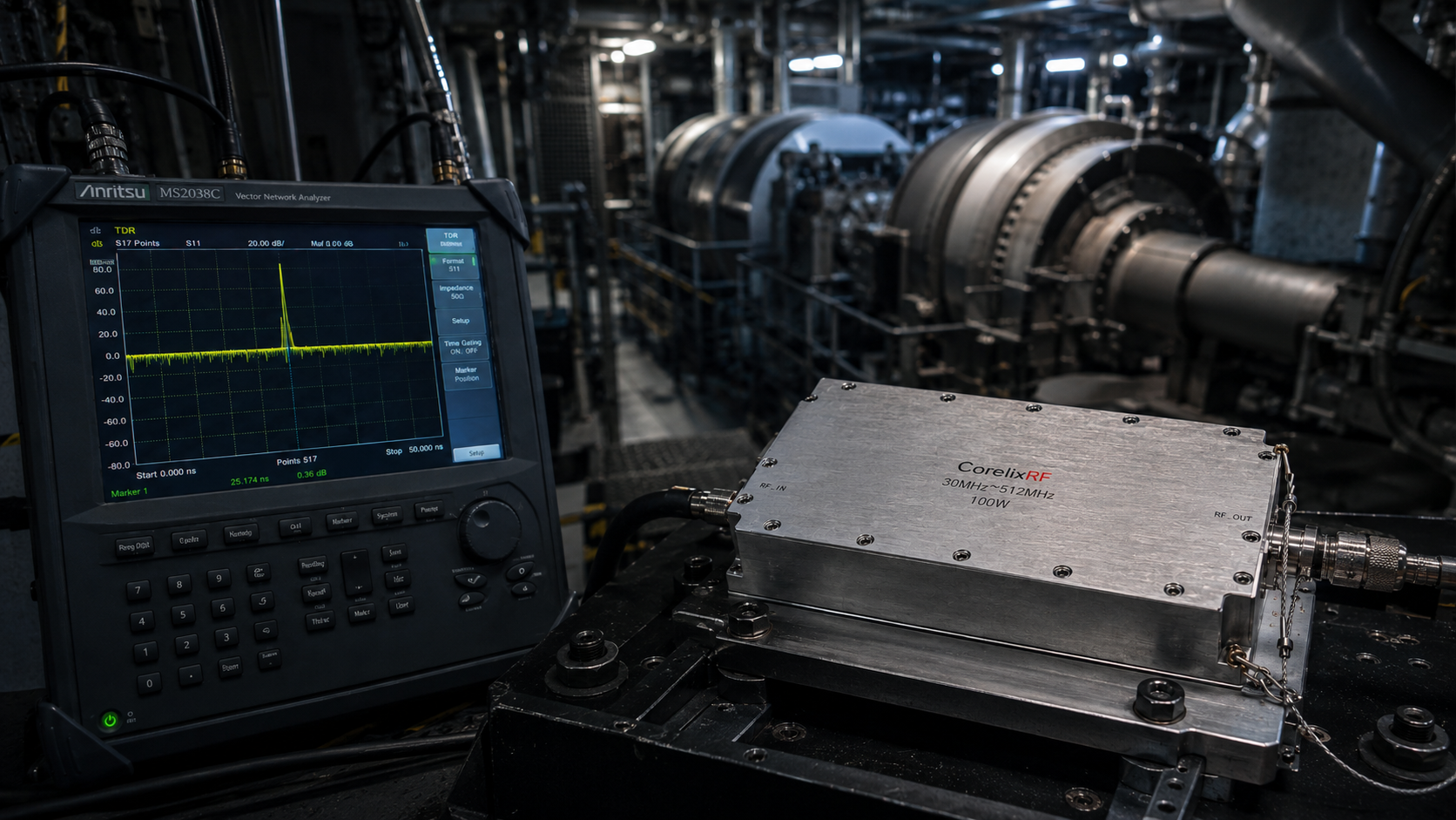
Troubleshooting blindly wastes massive amounts of maintenance budgets quickly. You cannot simply guess which exact module failed among dozens racked together tightly. Ready for the good part? Field technicians must deploy portable Vector Network Analyzers directly into active machinery spaces. Utilizing advanced Time Domain Reflectometry techniques provides exact physical distances toward impedance mismatches accurately.
● Interpreting Time Domain Reflectometry (TDR) plots for fault location.
TDR plots display unmistakable sharp spikes exactly where fractured solder joints sit inside sealed amplifier housings. Another hardcore diagnostic technique involves active physical tapping while observing live screens. Engineers monitor live return loss sweeps while gently tapping cable assemblies using non-metallic plastic tools. Sudden sharp jumps seen across VNA screens confirm loose mechanical mating surfaces immediately.
● Performing active physical tap tests on coaxial cables.
This practical approach separates theoretical guesses from undeniable engineering truths on site. Relying solely upon automated software alarms leaves repair crews chasing phantoms endlessly through complex naval communication racks. Tapping a suspect N-type barrel adapter reveals hidden center pin wear instantly. Proper diagnosis requires mixing high-end microwave instruments with gritty physical inspection methods simultaneously. True field veterans trust their hands just as much as their million-dollar analyzers.
Field Diagnostic Equipment Matrix
| Tool Name | Primary Function | Fault Detection Capability | Environment Suitability |
| Digital Oscilloscope | Baseband waveform analysis | Poor for RF faults | Lab testing only |
| Portable VNA | Broadband impedance profiling | Excellent | High noise areas |
| TDR Analyzer | Exact distance measurement | Pinpointing micro-cracks | Narrow ship spaces |
5. What Are The Consequences Of Ignoring Microscopic RF Hardware Degradation?
● Experiencing catastrophic power module burnouts during missions.
Ignoring early warning signs guarantees catastrophic network failure eventually. Microscopic metallic cracks never heal themselves magically over time. Here is a harsh reality: reflected power bouncing from loose connections travels straight back into solid-state output stages. Transistors designed handling 100 watts forward cannot absorb 50 watts returning backwards safely. Semiconductor die junctions overheat rapidly under severe mismatch conditions.
● Losing critical communication links amidst naval deployments.
This rapid overheating causes complete transistor meltdown within mere milliseconds. Once final output stages blow, entire tactical communication links vanish instantly. Such unexpected blackouts during active marine patrols endanger vessel crew safety directly. Furthermore, continuous localized heating around loose N-Female connectors literally melts expensive coaxial cable dielectrics completely.
● Incurring massive replacement costs for burnt transmission lines.
Replacing burnt transmission lines running through watertight ship bulkheads costs tens of thousands of dollars historically. Procurement teams quickly learn cheap commercial modules end up costing exponentially more over extended vessel lifecycles. Investing upfront in properly ruggedized factory-direct hardware prevents massive financial losses entirely. Burnt Teflon insulators release toxic fluoropolymer gases into confined engineering spaces dangerously. Prevention remains significantly cheaper than emergency dry-dock repairs.
6. How Does CorelixRF Address Ship Engine Room RF Amplifier Challenges?
● Introducing robust mechanical anchoring techniques.
Solving extreme vibration requires fundamental physical redesigns rather than flimsy software patches. CorelixRF approaches product manufacturing strictly through physics-based engineering realities. Let me show you how: we tackle vibration head-on using specialized mechanical anchoring techniques throughout our entire product line. Heavy LDMOS transistors receive secondary mechanical steel fasteners. These fasteners couple dies directly onto thick aluminum baseplates tightly.
● Implementing advanced vibration dampening materials within enclosures.
We inject aerospace-grade silicone dampening compounds underneath critical PCB sections manually. This structural epoxy prevents glass-epoxy substrate flexion completely under heavy G-forces. Our 30-year manufacturing history provides deep insights regarding structural harmonic resonances affecting microwave circuits. Engineers run extensive finite element analysis simulating exact diesel engine frequencies against bare chassis designs.
● Designing custom PCB layouts resisting harmonic resonances.
This rigorous modeling guarantees zero overlapping resonance frequencies exist organically within our products. By shifting natural resonant frequencies away from dangerous 10-50 Hz bands, destructive physical amplification never occurs internally. We manufacture true B2B solutions meant for system integrators facing uncompromising deployment environments daily. Every single mounting screw utilizes specialized thread-locking fluid preventing gradual back-out.
Vibration Mitigation Engineering Techniques
| Critical Sub-Assembly | Standard Commercial Practice | CorelixRF B2B Solution |
| Main PCB Mounting | 4-point corner brass screws | 12-point distributed steel anchoring |
| Heavy Component Fixing | Wave solder only | Aerospace epoxy staking plus hand solder |
| Enclosure Material | Stamped thin sheet metal | Solid CNC milled 6061-T6 aluminum block |
7. What Makes CRF-PA-30M512M-100W Ideal For Extreme Marine Environments?
● Reviewing electrical characteristics ensuring stable 100W output.
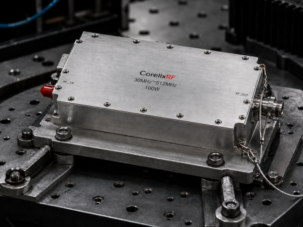
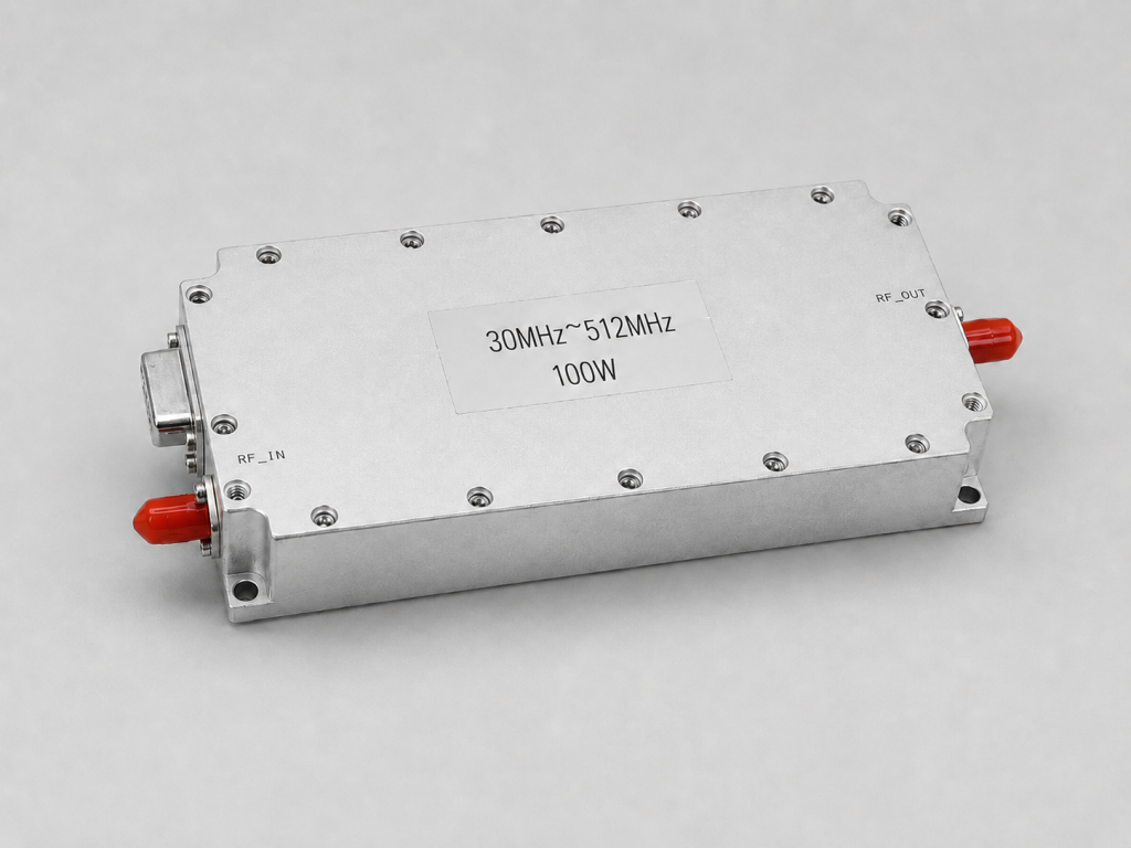
Naval integrators require predictable performance parameters combined with hardened physical traits. CorelixRF presents our definitive answer regarding shipboard amplification needs confidently. Consider this fact: our wideband module covers 30-512 MHz frequencies continuously. This broad spectrum capability makes integrating multi-role communication systems highly efficient. It delivers rated output power reaching 100 W flawlessly.
● Analyzing mechanical design accommodating 200 x 158 x 25 mm footprints.
We designed its package size specifically measuring 200 x 158 x 25 mm precisely. This compact footprint allows dense rack integration without sacrificing thick structural walls. The RF Input port uses SMA-Female formats while the RF Output utilizes ruggedized N-Female connectors. Both connectors feature extra-thick flange mounts preventing torque loss under mechanical duress.
● Detailing SMA-Female and N-Female connector structural integrity.
Running off standard 28 VDC supply voltages keeps integration simple. Total current consumption stays tightly bounded below 18 A max during full saturation. These exact specifications deliver absolute engineering truth directly into integrators hands. Cooling relies on forced air methods handling intense thermal loads gracefully. Total weight remains strictly under 1.4 kg, reducing rack strain significantly.
CRF-PA-30M512M-100W Electrical Characteristics
| Parameter | Typical Value | Maximum Limit | Units |
| Frequency Range | 30-512 | N/A | MHz |
| Rated Output Power | 100 | N/A | W |
| Current Consumption | N/A | 18 | A |
| Output VSWR | 1.5 | 2.0 | :1 |
8. How Do We Validate Performance Under Sustained Mechanical Stress?
● Examining gain flatness metrics during physical shaking tests.
Data sheets mean nothing without brutal factory validation backing every single printed number. Here’s the kicker: we bolt these modules onto industrial shaker tables simulating violent hurricane marine conditions constantly. Technicians monitor live S-parameters during intense multi-axis shaking procedures actively. We guarantee output VSWR never exceeds 2.0:1 limits even under maximum mechanical duress.
● Monitoring 28 VDC current draw stability across temperature shifts.
Current consumption from standard 28 VDC power supplies must remain absolutely stable. Any sudden fluctuation indicates internal component shifting or microscopic shorting instantly. We operate these units across extreme thermal boundaries ranging from -40 to +85 °C simultaneously. Cold starts inside freezing compartments test material elasticity limits thoroughly. Hot environments test transistor junction thermal resistance heavily.
● Verifying input VSWR staying below 1.8:1 maximum thresholds.
Our engineering team logs hours of swept measurement data continuously. We confirm gain stays locked tightly between 49 and 51 dB without faltering. Input VSWR remains strictly bounded below 1.8:1 maximum thresholds. We provide authentic reliability data upon request because our massive factory builds trust through transparent testing methodologies exclusively. Hardware surviving our test labs survives anything oceans throw at vessels.
9. What Installation Practices Prevent Future Troubleshooting Nightmares entirely?
● Routing cables carefully avoiding direct engine block contact.
Hardware ruggedization requires matching professional installation disciplines from field technicians always. Buying premium factory components solves only half your integration equation realistically. Now listen closely: cable routing demands meticulous attention inside tight engine spaces. Never strap coaxial transmission lines directly onto vibrating diesel engine blocks arbitrarily. Route expensive cables along secondary bulkheads utilizing specialized shock-absorbing standoff clamps exclusively.
● Applying correct torque specifications using calibrated wrenches exclusively.
When connecting the SMA-Female input, use calibrated torque wrenches ensuring exact manufacturer specifications get met. Applying stainless safety wire across connector nuts prevents rotational back-off completely during extended ocean voyages. Wire-tying represents an old aerospace trick working perfectly inside maritime applications. Furthermore, secure DB9 control interfaces using proper screw locks.
● Utilizing strain relief mechanisms for all DB9 control cables.
Incorporate generous service loops providing immense strain relief for control harnesses. A tight cable acts exactly like a tuned guitar string mechanically. Tight cables transmit destructive vibrational energy straight into internal logic boards rapidly. Professional B2B installations treat every wire like a potential failure point needing proactive mitigation. Quality installations double the operational lifespan of any solid-state amplifier module automatically.
Mandatory Field Installation Checklist
| Component Area | Required Action | Verification Method |
| N-Female RF Output | Apply stainless safety wire | Visual Inspection |
| Main Coaxial Cable | Install shock-absorbing clamps | Manual pull test verification |
| DB9 Control Line | Secure locking screws firmly | Mechanical twist check |
| Module Chassis | Bond ground strap directly | Milliohm meter testing |
10. How Should System Integrators Plan Their Next Naval Communication Upgrades?
● Assessing current MTBF data against operational requirements.
Upgrading legacy systems requires viewing entire network architectures through a pragmatic engineering lens. System integrators must stop buying consumer-grade hardware for defense-level maritime applications immediately. This changes everything: start by gathering exact Mean Time Between Failure data dictated by your specific naval contracts. Compare those aggressive numbers against realistic environmental stressors present within shipboard engine rooms.
● Requesting specific feasibility reviews from factory engineering teams.
Reach out directly towards primary manufacturers possessing actual heavy factory capabilities rather than dealing through third-party resellers. Our dedicated engineering team provides custom feasibility reviews within 48 hours precisely for complex integration projects. We alter frequency bands, customize control interfaces, and modify connector placements depending on strict mechanical constraints smoothly.
● Securing reliable components delivering true Engineering Truth.
Choosing components built fundamentally upon engineering truth guarantees your next deployment survives decades rather than mere months underway. Modern naval warfare relies completely upon uninterrupted data links maintaining situational awareness. Do not let a ten-cent loose connector bring down a billion-dollar platform. Partnering directly with experienced RF factories removes supply chain guesswork completely. True engineering solves problems permanently.
Surviving extreme low-frequency vibration environments demands purpose-built microwave hardware engineered specifically against intense mechanical destruction. Standard components inevitably fail inside brutal naval engine spaces, causing catastrophic mission downtime quickly. Deploying properly ruggedized solutions like the CRF-PA-30M512M-100W eliminates intermittent connector faults and internal solder fractures completely. Contact our engineering team today for detailed datasheet specifications and secure absolute reliability for your next tactical maritime communication integration project.
FAQ Section
Q1: What is the main cause of intermittent VSWR alarms inside ship engine rooms?
Low-frequency vibrations from massive diesel turbines cause physical connector loosening and internal component shifting, leading directly to sudden impedance mismatches and reflected power spikes.
Q2: How do low-frequency vibrations destroy standard RF connectors?
Continuous mechanical resonance creates micro-friction between threaded surfaces, slowly backing off locking nuts and creating air gaps that violently alter the characteristic 50-ohm transmission line impedance.
Q3: Why do internal micro-solder joints crack under constant resonance?
Rigid lead-free solder alloys exhibit high brittleness, which fractures when heavy surface-mounted components act like pendulums while printed circuit boards flex continuously under heavy acoustic vibrations.
Q4: How can field engineers diagnose hidden connection failures effectively?
Technicians deploy portable Vector Network Analyzers using Time Domain Reflectometry to pinpoint exact fault distances, alongside physical tap tests observing live return loss fluctuations on screens.
Q5: What makes CRF-PA-30M512M-100W ideal for extreme marine environments? This model integrates robust mechanical anchoring, aerospace-grade vibration dampening, and ruggedized connectors delivering stable 100 W output across 30-512 MHz frequencies reliably.
Turn this RF requirement into a quotable specification
Use this article as a starting point for a buildable RF specification. Before quoting, CorelixRF normally checks frequency range, output power, gain flatness, duty cycle, load mismatch, thermal path, control interface, enclosure limits and acceptance data.
- rugged RF systems – review ruggedization expectations for vibration, thermal and field maintenance
- RF front-end platform – compare the RF chain as a system instead of selecting one isolated module
- RF power amplifier platforms – match the article topic to available RF power amplifier families
- broadband SDR signal source – connect waveform or signal-source requirements to the RF front-end
- RFQ checklist – send the data buyers usually forget, including band, power, duty cycle, interface and test standard
- delivery documentation – check what documents can support incoming inspection, FAT review and long-term maintenance
- engineering contact – send the application notes, block diagram or target specification to engineering sales
For a faster review, send operating band, power target, modulation or waveform, antenna/load condition, cooling limit, mechanical envelope and target test standard through the RFQ or contact path.