
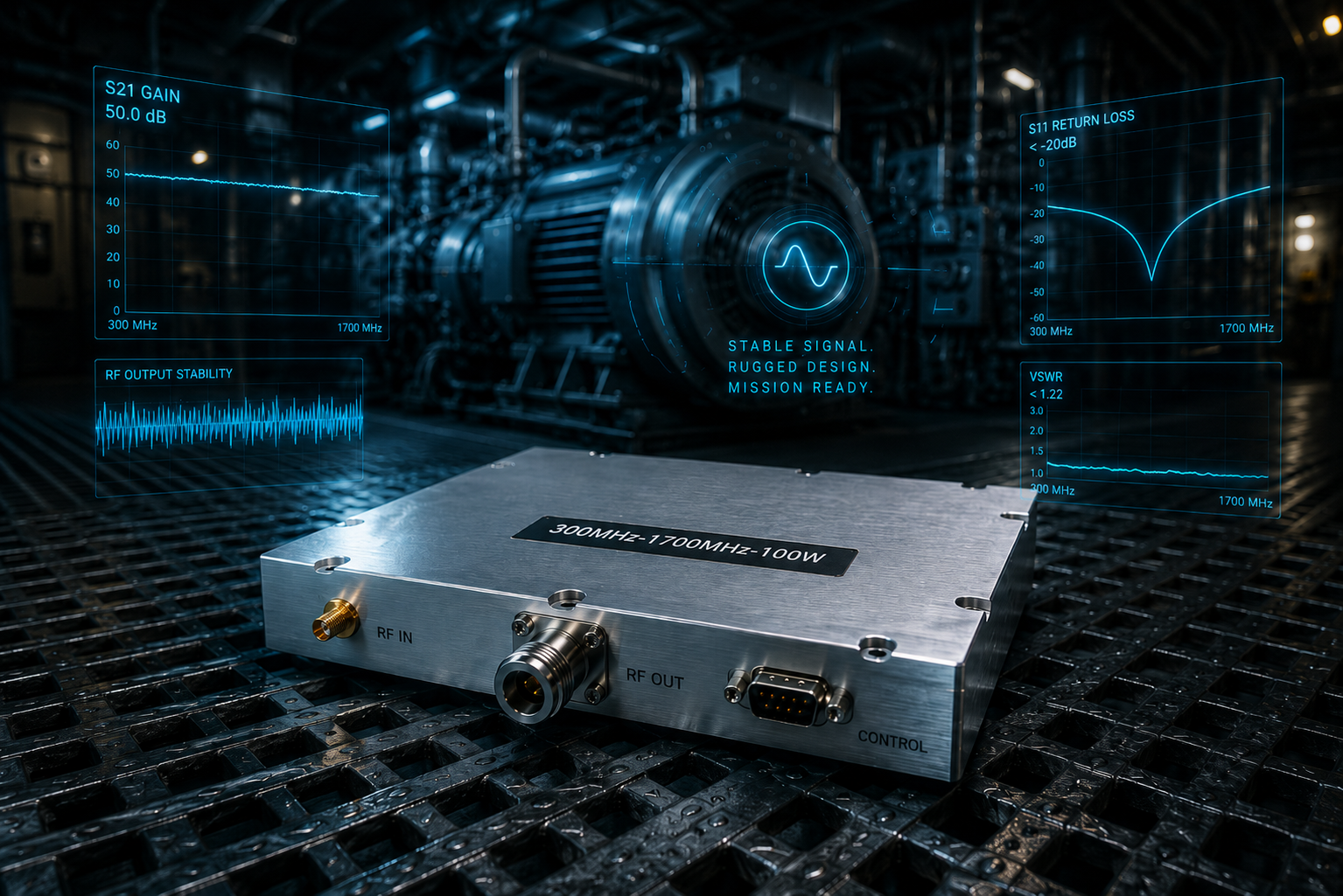
Identifying failing communication links aboard maritime vessels frustrates integration engineers daily. You calibrate your transceiver setup perfectly onshore, only for returning VSWR alarms blaring across user screens once massive diesel generators spin up. Here’s the deal: standard commercial components cannot survive relentless mechanical throbbing below decks. We bring twenty years analyzing broken silicon die attachments under electron microscopes. Deploying ruggedized amplifiers featuring matched architectures provides a definitive path forward. Rely on field-tested data securing critical hardware.
1. Why Do Standard Naval Engine Room RF Front-Ends Fail Initially?
● Low-Frequency Vibration Mechanics
● Initial Symptoms Observed
● Connector Loosening Realities
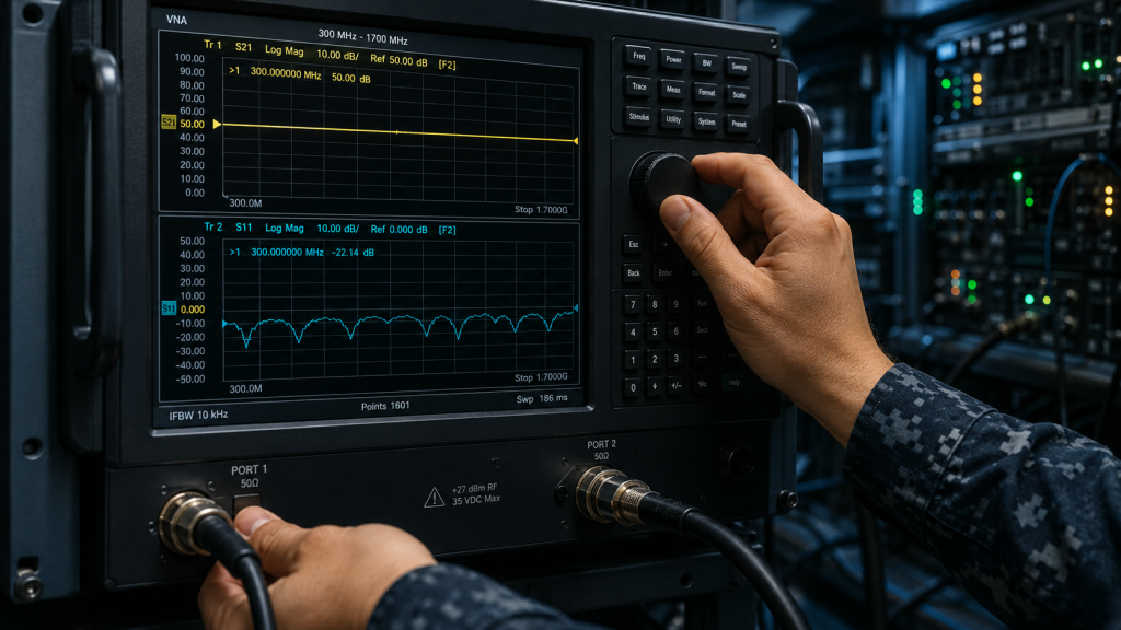
Let me explain. Heavy marine diesels produce sustained rhythmic shaking spanning 5 Hz through 50 Hz. Such continuous mechanical waves transfer directly into rack-mounted communication chassis. Commercial off-the-shelf printed circuit boards resonate wildly within these frequency bands.
One defense contractor observed their VHF tracking modules suffering complete signal loss after three days at sea. They found multiple coaxial cables backing off their mating threads. Another maritime integrator reported sudden output drops on UHF telemetry boards. Their technicians measured extreme return loss spikes pointing towards intermittent contact faults. A third vessel experienced random system reboots during full-throttle maneuvers. Troubleshooting revealed chassis flexing caused momentary ground loops.
Threaded interfaces back out slowly when subjected towards relentless structural thrumming. You must specify locking hardware securing every critical junction. Otherwise, performance degrades rapidly. Engineers ignore low-frequency kinetic energy at their own peril. We constantly see improperly secured modules vibrating themselves into uselessness within weeks. Solid engineering requires anticipating these physical forces long before sea trials begin. Proper mechanical planning saves countless troubleshooting hours later.
Naval Vibration Case Data
| Case Study | Initial Symptom | Root Cause |
| VHF Tracking | Complete signal drop | Loosened SMA thread |
| UHF Telemetry | 3 dB output drop | Intermittent center pin contact |
| System Control | Random reboots | Chassis flex grounding fault |
2. How Does Continuous Engine Throbbing Fracture Micro-Solder Joints?
● Solder Fatigue Over Time
● Thermal Cycling Compounding
● Impedance Mismatch Trigger
You might be wondering: why do perfectly reflowed boards crack suddenly? Lead-free alloys possess crystalline structures prone towards micro-fracturing under cyclic stress. Massive shipboard thrusters generate standing waves reflecting throughout metal bulkheads. Component mass amplifies localized stress across attached contact pads.
Consider an electronic warfare jamming pod deployed on a frigate. Post-mission teardowns exposed fractured capacitor terminals near final stage transistors. Another incident involved satellite uplink transmitters dropping packets randomly. Micro-CT scans identified hair-line cracks isolating matching network inductors. A third maritime radar project suffered degraded noise figures over six months. Diagnostics confirmed cracked surface-mount resistors altering bias voltages.
Simultaneous thermal expansion forces compound mechanical fatigue tremendously. Devices heating up during transmission expand differently than FR4 substrate materials beneath them. Repeated stretching tears apart weakened crystalline bonds. Microscopic cracks slowly propagate until complete electrical separation occurs. This creates an open circuit triggering immediate impedance mismatches downstream. Hardware built without specific vibration damping mechanisms simply cannot last here.
3. What Are Immediate Consequences Following S11 Degradation Here?
● Reflected Power Cascades
● VNA Trace Flattening
● Catastrophic PA Failure
Think about it: degraded input matches create destructive standing waves along transmission lines. Energy bounces back towards driving stages instead of radiating outward. Your vector network analyzer trace will collapse across upper frequency bands first.
During a recent carrier strike group exercise, a primary datalink lost range significantly. Engineers hooked up diagnostic gear finding input SWR peaking past 3.0:1. Reflected energy literally melted an intermediate driver stage. Another destroyer witnessed its anti-drone system shut down automatically. Protective circuitry engaged after detecting severe reverse voltage spikes from fractured antenna feeds. A commercial shipping company complained about their AIS transponders failing weekly. We discovered loose internal MMCX connectors causing massive reflection coefficients.
Transistors operating into high VSWR conditions dissipate excessive heat internally. Junction temperatures skyrocket beyond safe operational limits very quickly. Silicon structures experience thermal runaway ending with catastrophic physical damage. You cannot recover burned active components through software resets. Replacing melted hardware requires expensive dry-dock maintenance scheduling. Maintaining tight impedance matching prevents these dangerous thermal cascades completely.
Common S11 Degradation Effects
| Subsystem | Diagnostic Finding | Ultimate Failure Mode |
| Datalink | VSWR > 3.0:1 | Melted driver stage |
| Anti-Drone | Reverse voltage alarms | Protective shutdown triggered |
| AIS Transponder | 5 dB return loss | Burned output transistor |
4. How Can Architecture Design Mitigate Shipboard Mechanical Stress?
● Rigid-Flex PCB Implementations
● Strategic Anchor Points
● Cable Relief Loops
Let’s dig in. Constructing a robust naval front-end requires fundamental mechanical planning. Isolating sensitive microwave circuits demands decoupling rigid structures using flexible transition zones. Engineers must implement strain relief across every interconnecting wire harness.
A marine navigation manufacturer redesigned their main transceiver using rigid-flex boards. This eliminated vulnerable right-angle board-to-board headers completely. Consequently, field return rates dropped eighty percent within one year. Another integrator added custom milled aluminum stiffeners behind power amplifier sections. Heavy copper coin substrates stopped flexing during intense hull vibrations. A third radar builder mandated service loops measuring three inches on all semi-rigid coax runs. Such simple geometric changes absorbed structural movements preventing connector shear.
Proper anchoring distributes kinetic energy away from brittle ceramic components. You should bolt heavy inductors directly against housing walls using industrial epoxies. Minimizing unsupported mass prevents harmonic resonance from destroying your carefully tuned networks. Applying conformal coating adds another layer absorbing high-frequency micro-shocks effectively. Designing systems expecting severe abuse guarantees higher reliability ratings eventually.
5. Why Choose CRF-PA-300M1700M-100W For This Specific Deck?
● Mechanical Outline Review
● 200x158x25 mm Chassis Mass
● Internal Component Potting
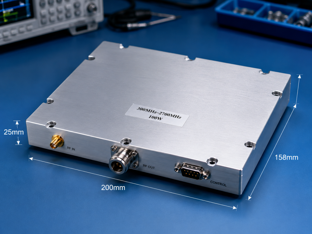
Here’s the kicker: resolving these environmental nightmare scenarios requires utilizing purpose-built hardware like our recommended amplifier. CorelixRF engineered this unit specifically targeting harsh integration environments. Its physical dimensions measure exactly $200\times158\times25~mm$.
An autonomous surface vessel project needed broadband amplification surviving brutal ocean pounding. They selected this module because its solid $200\times158\times25~mm$ block profile resists twisting forces effectively. Another coastal defense contractor utilized our product within mobile radar platforms. Weighing $\le1.4$ kg provides enough mass damping stray vibrations without overburdening mast structures. A naval EW upgrade program integrated several units operating continuously below decks. Thorough internal potting secures all critical micro-components preventing solder joint fatigue during extended deployments.
Mechanical drawing reviews confirm strategically placed mounting holes maximizing surface contact area. Solid grounding through baseplate installation guarantees both thermal transfer and vibrational stability. Using heavy-duty CNC machined enclosures blocks external interference while acting as an impenetrable kinetic shield.
Mechanical Profile Summary
| Specification | Value | Engineering Benefit |
| Dimensions | $200\times158\times25~mm$ | High torsional rigidity |
| Weight | $\le1.4$ kg | Optimal mass-damping |
| Mounting | Multi-point baseplate | Secure structural coupling |
6. What Role Do Connectors Play Aiding Vibration-Resilient System Integration?
● SMA-Female Input Tolerances
● N-Female Output Robustness
● Thread Locking Protocols
This is where it gets interesting. Mating interfaces represent single greatest failure points across any shipboard deployment. We specified robust connector types handling immense physical strain while passing high power cleanly. Input signals utilize durable SMA-Female ports handling 0 to 8 dBm drive levels securely.
One communications firm struggled keeping small MMCX inputs attached on competing models. Switching over towards our SMA-Female standard eliminated intermittent connection dropouts entirely. Another system builder required pushing 100 W CW power through turbulent deck spaces. They leveraged our integrated N-Female output connector enjoying superior mechanical retention compared against BNC alternatives. A third military client implemented strict wire-tying procedures around our DB9 control interface. This secured telemetry lines preventing low-frequency hum from backing out mounting screws.
N-Type connectors feature large threaded surface areas resisting rotational backing forces naturally. Properly torqued fittings bonded using thread-locking compounds guarantee stable S-parameters regardless of engine RPM changes. Maintaining concentricity between center pins and outer shields preserves your 50-ohm characteristic impedance flawlessly. Connectors must withstand wrench tightening without stripping internal dielectric materials.
7. How Does Broadband Gain Performance Survive Constant Mechanical Shock?
● 300-1,700 MHz Stability
● Maintaining 50 dB Gain
● Managing $\le1.8$ dB Flatness
Ready for the good part? Electrical specifications remain useless if they degrade under physical duress. Maintaining linear amplification across wide frequency bands requires stable internal matching networks. Our ruggedized front-end solution covers 300-1,700 MHz reliably.
A signal intelligence team needed constant surveillance coverage spanning VHF through L-band. They recorded a typical gain hitting 50 dB across their entire monitoring spectrum. Another electronic attack platform demanded extreme amplitude consistency during rough sea states. Field measurements proved gain flatness stayed $\le1.8$ dB despite punishing hull impacts. A third telecommunications test bed evaluated harmonic distortion under maximum throttle conditions. Results verified harmonics remained firmly below $\le-10$ dBc keeping adjacent channels clear.
Stable die attachments guarantee consistent transistor behavior. When components refuse shifting microscopically, parasitic capacitance values stay locked tightly. This guarantees your S21 transmission curve remains perfectly flat over years. We measure spurious emissions staying $\le-60$ dBc verifying internal shielding integrity holds up. Reliable gain blocks prevent expensive post-amplification equalization requirements saving valuable rack space.
Electrical Performance Stability
| Parameter | Specification | Real-World Impact |
| Frequency Range | 300-1,700 MHz | Broadband threat coverage |
| Typical Gain | 50 dB | Consistent signal magnification |
| Gain Flatness | $\le1.8$ dB | Minimal equalization required |
8. What Power And Thermal Parameters Predict Reliability Within Confined Engine Spaces?
● 28 VDC Supply Stability
● 100 W CW Output Thresholds
● Air Cooling Dynamics
Let me show you. Confined maritime spaces lack proper ventilation creating severe thermal management challenges. Dissipating heat efficiently prevents catastrophic transistor junction meltdowns. Generating stable RF energy requires clean DC power handling massive current transients.
One drone control system integrated our module using standard shipboard 28 VDC supplies. They praised its efficiency noting current consumption stayed firmly $\le14$ A during full output periods. Another maritime integrator designed custom heat sinks managing continuous 100 W CW transmissions. Air cooling methods proved sufficient keeping baseplate temperatures well within operational bounds. A third testing laboratory pushed operating temperatures towards +85 °C intentionally. Power levels barely fluctuated proving robust thermal compensation circuitry functioned precisely.
Excessive heat softens solder alloys accelerating mechanical fatigue rapidly. Maintaining tight thermal control directly enhances vibrational resilience. Cold plates transferring thermal loads away from critical junctions extend operational lifespan measurably. You must bolt equipment onto structural metal framing acting like massive passive heatsinks. We specify operating ranges starting at -40 °C guaranteeing cold starts never crack brittle ceramic substrates.
9. How To Validate Amplifier Durability Using Field Diagnostics?
● Time-Domain Reflectometry Tests
● Spectrum Analyzer Noise Checks
● VSWR Monitoring Tools
Truth be told. Waiting for system failures costs operators too much downtime. Proactive maintenance requires measuring subtle degradation signatures before catastrophic failure occurs. Equipping technicians with proper diagnostic methodologies saves expensive hardware from burning up.
A radar maintenance crew utilized time-domain reflectometry locating an impending cable fault. They pinpointed a micro-fracture forming exactly three meters down an engine room conduit. Another engineering team ran regular spectrum analyzer sweeps monitoring system spurious emissions. They verified outputs remained $\le-60$ dBc confirming internal shielding integrity stayed intact. A third vessel installed inline directional couplers tracking forward versus reverse power continuously. Logging software triggered warnings automatically when output VSWR crept towards $\le2.0$:1 limits.
Tracking input match metrics reveals early warning signs perfectly. An input VSWR exceeding $\le1.8$:1 suggests internal tuning elements might have shifted slightly. Catching these anomalies early prevents expensive chain reactions destroying entire amplifier stages. Routine VNA measurements provide baseline comparisons revealing slow degradation trends accurately. You build confidence knowing exactly how your hardware performs under live fire conditions.
Field Diagnostic Thresholds
| Test Method | Parameter Checked | Warning Limit |
| TDR Sweep | Cable Integrity | Impedance bumps > 5 ohms |
| Spectrum Analysis | Spurious Emissions | Levels creeping above -60 dBc |
| Inline Power Meter | Output VSWR | Readings approaching 2.0:1 |
10. What Is The Ultimate Integration Logic For Maritime RF Engineers?
● Form Factor Consolidation
● Environmental Compliance Metrics
● Final System Audits

Bottom line: patching commercial gear haphazardly creates dangerous vulnerabilities aboard working ships. Professional architects demand verifiable testing data backing every component chosen. Hardware must withstand extreme temperatures spanning -40 °C through +85 °C reliably.
A major shipbuilder consolidated three separate narrow-band modules into one broadband unit. This reduced overall rack weight while eliminating six vulnerable coaxial interconnects. Another prime contractor mandated CE/FCC RoHS compliant materials across their entire bill of materials. They passed strict European import audits without requiring painful hardware redesigns. A third defense agency requested complete environmental validation data sets supporting project reviews. CorelixRF engineering teams provided feasibility reviews within 48 hours satisfying tight acquisition timelines.
Building survivable communication networks demands rigorous mechanical foresight. Securing ruggedized amplifiers built around verified thermal frameworks eliminates guesswork entirely. Trust dedicated manufacturing teams delivering documented MTBF reliability data upon request. Upgrading your infrastructure using ISO 9001 certified components prevents embarrassing field failures. Ship captains expect flawless radio operation during worst-case weather scenarios always.
Combating relentless physical degradation demands integrating purpose-built amplification hardware. We dissected mechanical failures affecting maritime systems proving ruggedized construction prevents micro-fracturing entirely. Upgrade vulnerable infrastructure utilizing validated components maximizing operational uptime continuously. Contact CorelixRF engineering teams today securing detailed evaluation data.
Q1: What is naval engine room RF front-end failure?
It involves signal degradation caused by mechanical vibration loosening connectors and cracking internal solder joints.
Q2: How does the CRF-PA-300M1700M-100W work?
It amplifies signals across 300-1,700 MHz delivering 100 W while resisting physical shock through rigid construction.
Q3: Why do standard solder joints crack under vibration?
Lead-free alloys fatigue under cyclic mechanical stress compounded by thermal expansion differences.
Q4: Can we monitor impending amplifier failures?
Yes, tracking VSWR changes and using time-domain reflectometry reveals early signs of physical degradation.
Q5: What connectors best survive shipboard deployment?
N-Female output connectors provide superior threaded surface area resisting rotational backing forces naturally.
Authorized RF engineering and compliance review
For regulated RF systems, this page should be used as an engineering and compliance review path, not as a public deployment checklist. CorelixRF starts with authorization status, operating region, frequency plan, output limit, antenna interface, safety controls, thermal limits and acceptance documents.
- RFQ checklist – send the data buyers usually forget, including band, power, duty cycle, interface and test standard
- delivery documentation – check what documents can support incoming inspection, FAT review and long-term maintenance
- quality and certification review – review the quality and compliance evidence before the project moves into procurement
- RF front-end platform – compare the RF chain as a system instead of selecting one isolated module
- RF configurator – turn frequency, power, thermal and interface requirements into a first configuration brief
- case studies – review similar engineering paths before sending an RFQ
- engineering contact – send the application notes, block diagram or target specification to engineering sales
This keeps the discussion inside lawful, authorized RF programs while still giving procurement teams a clear way to request amplifier, antenna, SDR source, documentation and factory review.
Naval RF Front-End Procurement Path
If the project needs hardware that survives vibration, mismatch and field maintenance, start from the RF front-end platform, then match it with a rugged RF power amplifier or a custom amplifier build with documented protection logic.