
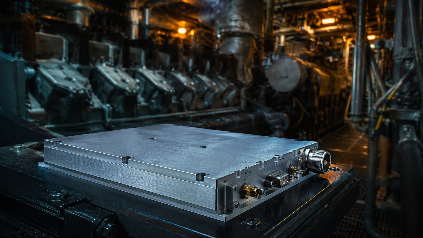
Architecture Analysis: High-Power Naval Engine Room Design Essentials: Engineering Practices to Combat Joint Loosening and Internal Micro-Solder Joint Cracking Caused by Long-Term Low-Frequency Vibration remains our main focus here. You stare at a flickering console deep inside a naval vessel. Massive diesel generators pound a continuous 15 Hz rhythm into your boots. Your forward-deployed jamming rack throws a sudden output power fault. This alarm indicates severe impedance mismatch occurring somewhere downstream. Our team sees this exact scenario constantly during field troubleshooting operations. Standard commercial hardware shakes apart under such relentless kinetic stress. We specify ruggedized hardware like our CRF-PA-300M2700M-100W wideband RF power amplifier against these breakdowns. Twenty years spent analyzing shattered circuit boards guarantees our uncompromising approach. Here’s the deal: understanding physical failure mechanics represents your first step toward building resilient shipboard electronic countermeasures.
1. Why Do Standard RF Amplifiers Fail Near Naval Diesel Generators?
Naval engine rooms present a uniquely brutal mechanical environment for precision electronics. Massive propulsion systems generate continuous kinetic energy across adjacent metal bulkheads. Huge diesel engines produce structural vibrations heavily concentrated within a 5 Hz through 50 Hz spectrum. Commercial equipment designers rarely account for such relentless low-frequency pounding. These slow rolling waves propagate straight into your sensitive transmitter chassis. We observe standard printed circuit boards behaving like trampoline surfaces. Central areas of unsupported fiberglass laminates start flapping vigorously up and down. You might be wondering: what exactly breaks first when this violent internal resonance begins? Surface-mount matching capacitors experience sheer tearing forces along their metallic end terminations. Lead-free solder joints become brittle over time under continuous mechanical cycling. We routinely map these failure zones using high-speed cameras. Our engineers redesign mounting architectures countering these exact acoustic threats directly. A fractured board trace immediately ruins transmission line characteristic impedance. Operators notice output power dropping drastically whenever engines throttle upwards. Fixing these mechanical failures requires robust custom enclosures bypassing traditional sheet metal designs completely.
Structural Resonance Factors
| Parameter | Commercial Standard | Naval Engine Room Reality |
| Primary Vibration Frequency | > 100 Hz (Fans) | 5 – 50 Hz (Diesel Engines) |
| PCB Deflection Amplitude | < 0.1 mm | > 1.5 mm |
| Material Fatigue Life | 100,000 cycles | 10,000,000+ cycles |
| Solder Joint Strain | Minimal | Extreme Shear |
2. How Does Low-Frequency Resonance Destroy RF Connector Integrity?
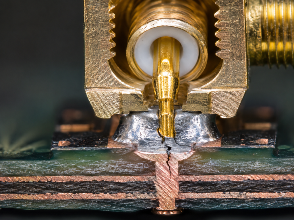
High-power RF interfaces represent serious mechanical vulnerabilities on equipment chassis bulkheads. Large diameter coaxial lines act like rigid lever arms transferring immense torque. Naval installations require thick heavily shielded cables resisting bending naturally. These thick cables transmit shipboard vibrations with terrible mechanical efficiency. What’s the real story? An SMA-Female input port or N-Female output port takes a massive physical beating. Central conductor pins experience microscopic frictional scraping against their mating female socket contacts. This continuous micro-motion strips away protective gold plating layers revealing bare copper alloys underneath. Oxidation rapidly sets in across these exposed surfaces driving contact resistance values higher. Micro-solder joints connecting these center pins down onto fragile microstrip traces eventually crack. Your once-perfect 50-ohm transmission line suddenly becomes an open circuit. This broken path triggers immediate downstream system protection faults instantly. We consistently find cracked solder beads hiding underneath heavy connector flanges. Replacing broken connectors wastes valuable mission time during active sea deployments.
Connector Stress Analysis
| Interface Type | Cable Torque Load | Vibration Transfer Rate | Failure Mode |
| SMA-Female | Moderate | High | Center pin micro-crack |
| N-Female | Severe | Very High | Solder pad delamination |
| DB9 Control | Low | Moderate | Pin fretting |
3. What Are Link Budget Consequences Of Unnoticed Micro-Cracking?
Undetected mechanical fractures inside microwave components inflict devastating consequences upon calculated system link budgets. A fractured solder joint often maintains intermittent physical contact randomly. This bouncing connection creates extreme fluctuations regarding overall transmission line impedance matching. We observe these phenomena vividly using vector network analyzers aboard active vessels. Reflected power spikes violently backwards toward driver stages causing internal loop confusion. This is where it gets interesting An ideal input VSWR specification of ≤ 1.5:1 swings past 3.0:1 during engine surges. Harmonics previously suppressed below -10 dBc spike dangerously upward due solely toward nonlinear reflections. Your output power level drops erratically leading operators toward assuming software glitches. Tracking down transient impedance anomalies demands rigorous phase-stable testing methodologies. Faulty cables sometimes mask actual internal amplifier connector failures temporarily. Engineers must isolate each block systematically while propulsion shafts rotate continuously. Ignoring intermittent VSWR alarms guarantees eventual complete transmitter destruction.
RF Performance Degradation Metrics
| Specification | Healthy State | Micro-Cracked State |
| Output Power | 100 W | Fluctuating 20-80 W |
| Input VSWR | ≤ 1.5:1 | Intermittent > 3.0:1 |
| Harmonics | ≤ -10 dBc | Variable -5 dBc |
4. How Does The CRF-PA-300M2700M-100W Structure Prevent Fatigue?
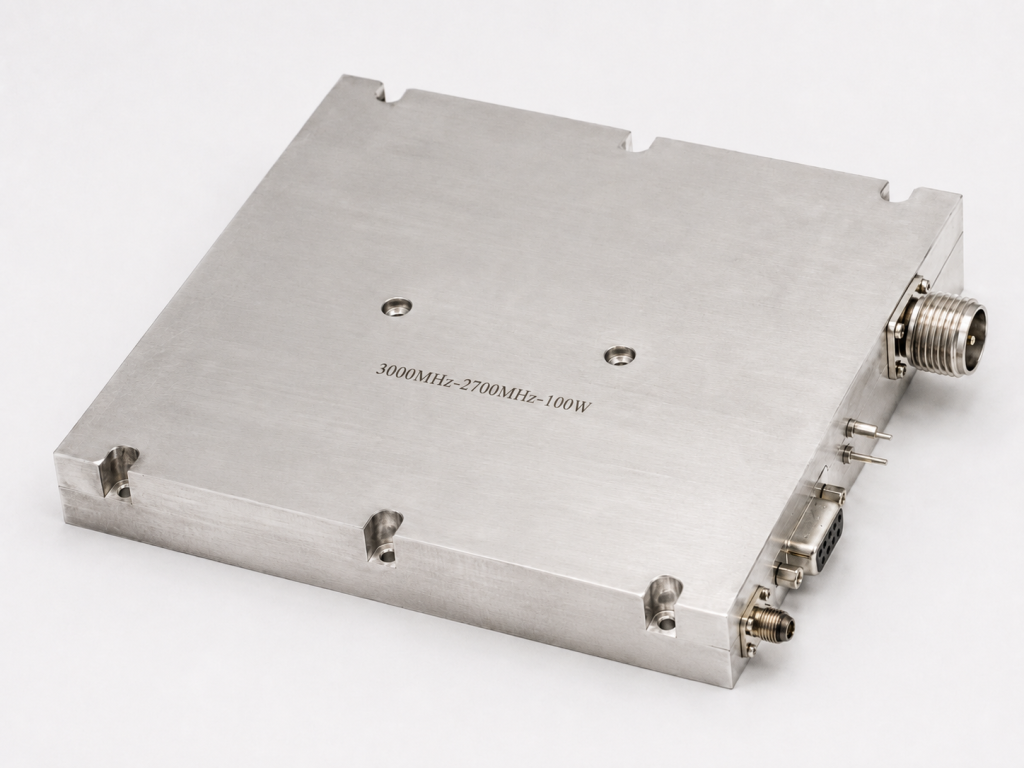
Surviving extreme kinetic environments requires treating electronics packaging fundamentally as an advanced mechanical challenge. CorelixRF designed our specific 200 x 158 x 25 mm chassis exclusively for preventing board flexion. Thick aerospace-grade aluminum forms a rigid monolithic baseplate guaranteeing absolute planar stability. We strategically scatter mounting screw locations precisely disrupting natural acoustic resonant modes. Ready for the good part? Our engineers meticulously secure every massive RF matching component using military-grade epoxy. The DB9 control connector features custom strain relief anchoring directly into thick metal walls. A total mass weighing ≤ 1.4 kg minimizes overall inertial moment forces generated during maneuvers. This rigorous mechanical lockdown guarantees internal electrical nodes remain completely stationary. External engine vibrations pounding against equipment racks cannot penetrate our milled aluminum housing. We eliminate weak sheet metal covers prone toward vibrating at 15 Hz entirely. Solid metal enclosures act like massive acoustic dampers protecting sensitive microwave traces.
Mechanical Specifications
| Feature | Value | Engineering Benefit |
| Package Dimensions | 200 x 158 x 25 mm | Low profile reduces torque |
| Total Weight | ≤ 1.4 kg | Low inertial mass |
| RF IN Connector | SMA-KFD46 | Flange mounted |
| RF OUT Connector | N-Female | Heavy duty anchoring |
5. Why Is Broad Frequency Coverage Necessary Despite Mechanical Challenges?
Modern electronic warfare applications demand instantaneous frequency agility stretching across vast electromagnetic spectrums. Single-band transmitters no longer provide adequate tactical flexibility against modern radar systems. Integrating our architecture covering a 300-2,700 MHz frequency range delivers overwhelming tactical superiority. Achieving this massive bandwidth mechanically requires distributing dozens of bulky impedance matching networks. But here’s the kicker… Wideband distributed architectures inherently create larger target areas susceptible toward low-frequency structural damage. Every additional capacitor represents another potential failure node unless strictly reinforced mechanically. Supplying a continuous 100 W CW/Saturated output power uniformly dictates using physically large transistors. We fuse these huge active devices directly against solid aluminum flooring. This technique guarantees unbreakable thermal and structural integrity simultaneously. Complex wideband matching circuits survive brutal shaking because we pot them entirely. You maintain full broadband jamming capabilities regardless of ship kinetic conditions.
Electrical Characteristics
| Parameter | Minimum | Typical | Maximum |
| Frequency Range | 300-2,700 MHz | ||
| Output Power | 100 W | 100 W | |
| Gain | 49 dB | 50 dB | 51 dB |
| Spurious | ≤ -60 dBc |
6. What Thermal Considerations Accompany Vibration Hardening?
Dumping massive waste heat presents complex obstacles whenever engineers rigidize chassis enclosures. Heavy thermal potting compounds frequently utilized for vibration damping act like thick insulating blankets. Naval engine spaces routinely exhibit brutal ambient conditions far exceeding standard laboratory environments. Our design operates flawlessly across an extreme operating temperature span covering -40°C through +85°C. You might be wondering: how do we balance necessary physical rigidity alongside aggressive thermal demands? We employ high-density copper-tungsten alloy base flanges directly beneath all active power transistors. This localized material choice provides exceptional thermal conductivity while matching semiconductor expansion coefficients perfectly. An air cooling method works effectively here because we maximize internal heat spreader surface topologies. Our architecture successfully bleeds away intense heat without compromising overall structural stiffness. Cooling fans remain external avoiding introducing additional localized high-frequency vibrational noise. Heat dissipation paths remain incredibly short pulling temperatures directly away from delicate silicon junctions.
Thermal and Environmental Tolerances
| Specification | Value | Context |
| Operating Temperature | -40 to +85 °C | Engine room ambient |
| Storage Temperature | -40 to +85 °C | Shipyard storage |
| Cooling Method | Air Cooling | External fan forced |
| Max Current | ≤ 18 A | 504 Watts total DC input |
7. How Do We Verify Component Stability Using VNA Diagnostics?
Validating mechanical integrity within microwave assemblies demands sophisticated diagnostic equipment far beyond simple multimeters. Vector network analyzers expose microscopic physical flaws instantly by mapping forward transmission phases accurately. A representative swept measurement of gain (S21) and input match / SWR (S11) versus frequency reveals damage. Healthy modules exhibit exceptionally flat S21 curves maintaining an impressive gain flatness specification ≤ 1.5 dB. What’s the real story? We look specifically for sudden jagged drop-outs appearing along high-frequency portions of S21 traces. These sharp negative spikes indicate internal parasitic capacitances wildly fluctuating randomly. A tiny surface-mount component breaking loose from its solder bed causes these exact signatures. Tracking S11 return loss signatures simultaneously provides another critical layer of structural verification. Any massive degradation in broadband matching confirms engineers must stiffen particular regions further. We continuously monitor these traces during active vibration table testing verifying absolute stability.
Vector Network Analyzer Metrics
| Measurement Trace | Healthy Indication | Failure Indication |
| Tr1 S21 Log Mag | Flat, ~50 dB average | Jagged drop-outs, high variance |
| Tr2 S11 SWR | ≤ 1.5:1 across band | Spikes > 2.0:1 |
| Phase Response | Smooth linear progression | Sudden phase jumps |
8. What Are Upstream BOM Selection Pitfalls For Integrators?
System integrators frequently fall into dangerous traps when selecting commercial-off-the-shelf components. Purchasing departments naturally gravitate toward low-cost plastic encapsulated transistors cracking under continuous shipboard vibration. Substituting cheaper alternative substrate materials degrades high-frequency performance severely inside moist engine rooms. Our uncompromising bill of materials relies exclusively upon military-qualified ceramics and heavy gold plating. This is where it gets interesting A standard 28 VDC supply voltage necessitates massive internal reservoir capacitors handling transient currents. Choosing standard tall cylindrical electrolytic capacitors guarantees catastrophic failure based upon leveraged breaking forces. We strictly mandate low-profile ruggedized tantalum polymer arrays featuring multiple surface-mount solder tabs. These tabs distribute mechanical loads safely across available printed circuit board real estate. Such obsessive attention regarding component profiles separates professional defense contractors from amateur assembly houses. Smaller component masses resist violent acceleration forces infinitely better than taller generic alternatives.
Component Selection Guidelines
| Component Type | Commercial Mistake | Ruggedized Approach |
| Power Transistor | Plastic Overmolded | Ceramic Flange Mount |
| Decoupling Cap | Tall Electrolytic | Low Profile Tantalum |
| PCB Material | FR4 Standard | High-Freq PTFE Blend |
9. How Do We Implement Proper Gain Staging With This Architecture?
Deploying high-power active modules demands meticulous attention regarding upstream driver stages. Overdriving delicate input structures destroys sensitive gate peripheries instantly leaving hardware utterly useless. Our architecture requires a specific input drive for rated output ranging from 0 to 8 dBm. Applying signals exceeding this boundary risks immediate non-linear distortion degrading radar pulse modulation fidelity. Here’s the deal: generating a massive 50 dB typical gain means tiny input noise fluctuations multiply massively. Integrating high-quality bandpass filters before our module becomes strictly mandatory preventing noise amplification. Managing a maximum current consumption rating reaching ≤ 18 A demands thick gauge DC wiring. Properly engineered gain staging protects expensive frontend silicon while maximizing overall transmission distance. You must calculate cascaded noise figures assuming maximum engine room thermal conditions constantly. Attenuator pads placed precisely between driver stages prevent unpredictable standing waves forming dynamically.
Gain Staging Parameters
| Stage Metric | Required Range | Consequence of Violation |
| Input Drive | 0 to 8 dBm | Gate damage / Saturation |
| Typical Gain | 50 dB | Cascaded noise figure impact |
| Output VSWR Limit | ≤ 2.0:1 | Output device overheating |
10. What Are Final Integration Steps For Naval Engine Rooms?
Completing a successful hardware installation aboard combat vessels requires strict adherence concerning mechanical fastening protocols. Technicians must apply calibrated torque wrenches exclusively securing all baseplate mounting hardware tightly. We strongly recommend deploying wire-rope shock isolators beneath equipment racks filtering out those destructive engine harmonics completely. Custom connector integration details are available with CorelixRF engineering team providing feasibility reviews. Ready for the good part? Properly securing external thick coaxial cables using heavy padded P-clamps eliminates destructive lever forces. Securing control interfaces utilizing sturdy DB9 threaded standoffs prevents intermittent logic faults triggered mechanically. System integrators following uncompromising mechanical guidelines consistently achieve zero-defect operational records inside marine environments. Your final sign-off procedure must include sweeping entire operational bandwidths while main engines idle. Verifying absolute RF stability under active vibration remains your ultimate proof regarding installation quality.
Final Integration Checklist
| Integration Step | Tooling Required | Verification Method |
| Baseplate Mounting | Calibrated Torque Wrench | Feeler gauge flat check |
| Cable Strain Relief | Padded Metal Clamps | Visual physical shake test |
| RF Connector Torque | SMA / N Torque Wrench | VNA Return Loss Sweep |
System Sign-Off Procedures
Mastering high-power RF deployments inside violent naval engine rooms fundamentally requires abandoning delicate commercial design paradigms completely. We proved rigorous mechanical engineering focusing upon vibration mitigation prevents catastrophic solder joint fractures and connector fatigue continuously. Contact our CorelixRF engineering team today reviewing your specific shipboard architecture utilizing our robust platform.
FAQ Section
- Q1: What is the primary cause of RF amplifier failure in naval engine rooms?Low-frequency vibrations between 5 Hz and 50 Hz generated by massive diesel propulsion systems cause internal structural resonance destroying micro-solder joints.
- Q2: How does the CRF-PA-300M2700M-100W mitigate violent structural vibration? It utilizes a rigid milled aluminum chassis, low-mass components weighing ≤ 1.4 kg, and heavy military-grade epoxy bonding preventing circuit board flexion.
- Q3: What happens when an RF connector micro-solder joint cracks?The connection becomes intermittent causing wild impedance fluctuations, high VSWR spikes, and reflected power triggering automatic system protection shutdowns instantly.
- Q4: How do you verify mechanical integrity without opening the chassis?Engineers utilize Vector Network Analyzers monitoring S21 forward gain and S11 return loss traces during active vibration looking for sudden high-frequency signal drop-outs.
- Q5: Why are low-profile components strictly required for naval RF modules?Tall components like electrolytic capacitors possess high centers of gravity creating excessive torque and leverage snapping their own solder leads under kinetic stress.
Translate rugged-site symptoms into a complete RF-chain review
Rugged RF issues often combine grounding, vibration, thermal range, connector retention, signal source stability and amplifier power margin. Share the site condition and acceptance evidence needed before choosing a platform.
Recommended next step: send the operating band, output power target, duty cycle, load condition, control interface, protection or thermal limits and required FAT documents. CorelixRF can review this How to Design Chassis Structures Resisting RF Amplifier Vibration? requirement against standard RF amplifier platforms, RF front-end options and controlled customization paths.