
We will analyze specific RF module degradation physics occurring during armored vehicle deployments. This document provides actionable field diagnostic steps alongside specific hardware solutions tailored for severe mechanical stress. Our factory has investigated these physical failures for two decades. We present raw engineering truth regarding transmission line stability.
1. What triggers random VSWR warnings during tracked vehicle movement?
Picture sitting inside a mobile command post while metal tracks grind over broken concrete. You watch your terminal control screen constantly. Suddenly your system throws a high Voltage Standing Wave Ratio warning out of nowhere. Output power drops drastically. Your satellite link drops. Five seconds later operations recover completely. You might be wondering, what exactly just happened? Standard field tech manuals routinely blame weather fading or antenna pointing errors. We know from twenty years of analyzing returned field units that intermittent power loss in armored environments almost never stems from software bugs. Physical reality dictates that harsh kinetic energy transfers directly through vehicle chassis metal into your transmission line. Tracked vehicles generate massive low-frequency harmonics typically ranging from ten Hertz up past fifty Hertz continuously. These continuous shocks violently attack every threaded connection and rigid waveguide flange present. When an armored personnel carrier traverses rough terrain mechanical resonance loosens standard N-type threads fractionally. That fractional movement at Ku-band frequencies shifts impedance matches drastically. We repeatedly see field teams swapping entire Block Upconverters unnecessarily. Operators waste hours debugging control logic uselessly. Here’s the deal, a loose WR75 flange or a vibrating N-connector creates dynamic impedance mismatches instantly. This mismatch reflects microwave energy directly back into final amplifier stages causing immediate protection circuit activation.
Vibration Profile Comparison
| Vehicle Type | Dominant Frequency Range | Amplitude Peak | RF Failure Mode |
| Wheeled Truck | 5 Hz – 20 Hz | 2 G | Low |
| Tracked Armor | 10 Hz – 50 Hz | 5 G – 10 G | High |
| Commercial Van | 2 Hz – 10 Hz | 0.5 G | Negligible |
| Fixed Station | None | None | None |
2. Why do continuous low-frequency vibrations destroy generic RF components?
Armored chassis vibrations are relentless and brutally destructive. They do not just shake components superficially. They induce destructive harmonic resonance deep within printed circuit boards. What’s the real story? Standard FR4 or even high-frequency Rogers PCB materials possess specific natural mechanical frequencies. When track rumble matches this natural frequency your board bends violently. Microscopic flexing might measure only a few micrometers across a board span. Over hundreds of hours of mission time cyclic strain accumulates fatally. Solder joints bear maximum brunt regarding this mechanical torture. Standard commercial lead-free solders behave notoriously brittle under stress. They crack rapidly under continuous shear stress loading. We analyze failed commercial-off-the-shelf modules constantly within our labs. Under scanning electron microscopes cracked joints look like jagged geographical fault lines. RF paths become severely compromised instantly. At 14 GHz micro-cracks act like random variable capacitors. Cracks introduce erratic phase shifts and massive insertion loss spikes. Listen closely, engineers might test cracked modules on static laboratory benches seeing perfect performance. Fractures close tight when hardware sits stationary. Put that same module back into vibrating tank hulls and cracks open wide. Signal degrades instantly upon movement. Generic designs ignore structural dynamics completely. Manufacturers mount heavy RF chokes directly onto main boards without conformal coating.
Micro-Cracking Symptoms at Ku-Band
| Defect Type | Static Lab Bench Result | Active Field Result | Diagnostic Tool |
| Cracked Solder Joint | Pass | Random signal drop | Vibration Table + VNA |
| Loose SMA Center Pin | Marginal Pass | High VSWR alarms | Oscilloscope |
| PCB Delamination | Minor Phase Shift | Complete Link Loss | Thermal + Shock Test |
| Sheared Component | Fail | Fail | Visual Inspection |
3. How does microscopic solder fracturing alter microwave link budgets?
Broken solder joints do more than just attenuate raw signals. Fractures actively ruin your complex modulation schemes rapidly. Think about it for a second. Modern satellite communications rely heavily on phase-shift keying or quadrature amplitude modulation. These schemes require extreme phase linearity across data bursts. When solder joints crack physical gaps vary with every road bump. Micro-movements modulate carrier frequencies against mechanical vibration frequencies directly. You get severe phase noise degradation instantly. Systems requiring ≤-65 dBc/Hz at 100Hz offset will suddenly measure twenty decibels worse. Receiver demodulators lose phase lock immediately. Here’s the kicker, system software usually reports this event as generic atmospheric fading. Field engineers waste days realigning antennas tracking phantom ghosts. Mathematics proves physical reality beyond doubt. Gaps measuring 0.1 millimeters at 14.5 GHz introduce significant reactive impedance changes. Reactive components mismatched against 50-ohm systems cause immediate return loss events. Impedance mismatches eat into link margins aggressively. We calculate a single vibrating micro-crack injecting up to three decibels of random insertion loss. That cuts effective radiated power effectively in half. You cannot fix physics utilizing software patches. You need structurally hardened RF chains designed for kinetic warfare.
Impact of Mechanical Gap on 14 GHz RF Path
| Physical Gap Size | Estimated Insertion Loss | Phase Shift | Link Margin Hit |
| 0.01 mm | 0.2 dB | 2 degrees | Minimal |
| 0.05 mm | 1.1 dB | 8 degrees | Moderate |
| 0.10 mm | 3.5 dB | 25 degrees | Severe |
| 0.20 mm | >10 dB | Unpredictable | Complete Failure |
4. What diagnostic steps isolate loose RF connections in armored setups?
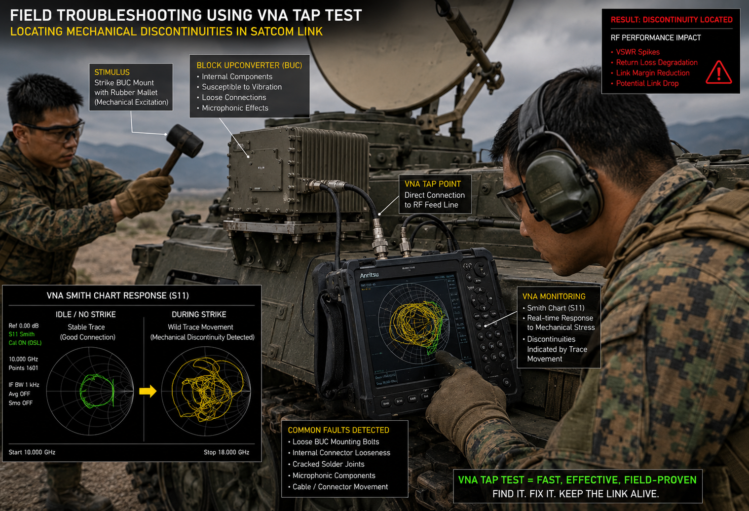
System drops demand incredibly fast mechanical troubleshooting responses. Relying on built-in test equipment often misleads technicians badly. BITE software averages sensor readings over long time windows. Averaging masks fast transient events caused by sudden mechanical shock. Ready for the good part? You need raw physical measurements taken immediately. Start by bypassing vehicle management software entirely. Connect portable Vector Network Analyzers directly into antenna feed lines. Set VNA devices into continuous sweep mode focusing on specific operating bands. Set frequency sweep limits from 13.75 GHz up through 14.5 GHz. Change display formats viewing Smith Charts specifically. Have an assistant physically strike BUC mounting brackets using rubber mallets. Watch carefully. Traces jumping wildly on Smith Charts indicate located mechanical discontinuities. Solid systems will show tight immovable dots or clean curves. We use this exact tap test during rigorous factory acceptance testing. Next inspect all waveguide flanges carefully. WR75 flanges require precise calibrated torque specs. Field mechanics often under-torque or over-torque bolts casually. Over-torquing warps flange faces permanently. Under-torquing allows vibrations separating mating faces easily. Both scenarios leak microwave energy spiking VSWR levels. Use calibrated torque wrenches every single time without fail.
Field Diagnostic Protocol for Vibration Failures
| Step | Action | Expected Normal Result | Failure Indicator |
| 1 | VNA Smith Chart Sweep | Stable trace during vibration | Trace jumps wildly |
| 2 | Flange Bolt Torque Check | All bolts at specified Nm | Loose or uneven bolts |
| 3 | Tap Test on Chassis | No change in RF output | Sudden drop in S21 |
| 4 | Spectrum Analyzer Hold | Clean carrier | Noise floor spikes |
5. How do engineers spot internal component failures using a spectrum analyzer?
External connections sometimes hold tight while internal electronics crack silently. Opening sealed IP65 chassis inside dusty motor pools remains impossible. You must diagnose hardware status from outside boundaries. This is where it gets interesting. Connect spectrum analyzers directly looking at test ports. Set narrow resolution bandwidth filters capturing fine details. Look closely at noise floors surrounding carrier frequencies. Failing internal solder points act like variable capacitors under vibration. Variable capacitance generates broadband noise pumping synchronously with engine RPM. Let that sink in. Engine speed directly correlates with observed RF noise floor fluctuations. We call this phenomenon microphonic noise generation. Microphonics prove internal physical components vibrate independently from main boards. Another telltale sign involves observing intermodulation distortion products closely. Required IM3 specifications dictate ≤-25 dBc at 3 dB rated power back-off. Cracked joints introducing non-linear impedance worsen IM3 products suddenly. Injecting two clean test tones at IF ports yields horrible sidebands. Bad sidebands mean internal power amplifier stages operate outside linear regions. Bias voltage paths altered by physical defects destroy amplifier linearity.
Spectrum Analyzer Signatures of Physical Damage
| Observation | Likely Physical Cause | Action Required |
| Elevated Noise Floor matching RPM | Microphonic component vibration | Replace Unit |
| Degraded IM3 Sidebands | Cracked bias circuit solder joint | Replace Unit |
| Random Carrier Power Drops | Fractured RF signal path | Check Connectors |
| Phase Noise Shoulders | Faulty LO reference connection | Verify 10MHz input |
6. What specific hardware attributes allow the CRF-BUC-Ku-100W to survive?
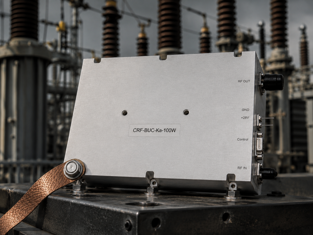
We designed CRF-BUC-Ku-100W specifically defeating these harsh mechanical realities. Our unit provides ≥50 dBm saturated output power surviving relentless kinetic abuse. Here’s the secret. Factory engineers abandoned standard commercial assembly techniques entirely. Internal RF matching networks utilize specialized high-flexibility substrates instead of rigid FR4. We bond heavy microwave components directly into aluminum chassis metal. Bypassing PCB solder joints transfers mechanical mass away from delicate electrical connections. You need to know this. Chassis dimensions measure exactly 225 × 151 × 141 mm weighing 5.5 kg. CNC machines mill enclosures from solid aluminum blocks eliminating resonance cavities completely. Power interfaces utilize robust three-pin aviation connectors exclusively. Communication interfaces utilize ruggedized RJ45 aviation connectors preventing data loss. We prohibit standard plastic plugs anywhere across exterior surfaces. Plastic degrades rapidly shattering under thermal and mechanical stress. Our design integrates built-in high-power isolator components protecting amplifier circuits. External waveguides vibrating loose cause massive energy reflections backward. Built-in isolators absorb returning energy protecting final Gallium Nitride stages perfectly.
CRF-BUC-Ku-100W Mechanical Defense Mechanisms
| Component | Standard Commercial Approach | CorelixRF Engineering Solution |
| Heavy Components | Soldered to PCB only | Screwed directly to metal chassis |
| Power Connector | Plastic DC jack | Metal three-pin aviation connector |
| Enclosure | Cast aluminum | CNC milled solid aluminum |
| Reflected Power | None | Built-in high-power isolator |
7. How does the thermal management design prevent stress compound fractures?
Kinetic vibration rarely acts alone destroying equipment in field deployments. Armored vehicles operate across burning deserts and frozen tundras continuously. Thermal cycling forces metal alloys expanding and contracting constantly. Why does this matter? PCBs expanding at different rates than aluminum housings create massive shear forces. Shear forces rip mounting screws and solder pads apart. Adding vibration against strained states snaps circuit boards quickly. We engineered CRF-BUC-Ku-100W operating safely from -40 °C up through 60 °C. Factory designs match thermal expansion coefficients between specialized RF boards and carrier plates. Truth be told, we utilize specific indium-based solders securing critical high-power junctions. Indium remains ductile absorbing shock even at freezing temperatures. Operating units draw 450 W typical power consuming heavy current. Managing massive heat requires aggressive forced air cooling techniques. Designs incorporate dual high-reliability fans resilient against dust meeting IP65 ratings. Heat sink fins sit mathematically spaced avoiding acoustic resonance matching cooling fans. Fins vibrating sympathetically against fan blades hum loudly and eventually fracture. Mathematical modeling prevents this exact catastrophic thermal failure mode.
Thermal and Environmental Specifications
| Parameter | Specification | Engineering Purpose |
| Operating Temperature | -40 °C to 60 °C | Sustains extreme field deployments |
| Storage Temperature | -45 °C to 75 °C | Safe transport in unconditioned holds |
| IP Rating | IP65 | Stops dust and directed water jets |
| Power Consumption | 450 W typical | Requires specialized thermal dissipation |
8. Why do we enforce strict RF interface requirements like N-F and WR75?
Pushing 100 watts of Ku-band energy through flimsy connectors fails quickly. Physics simply forbid weak connections surviving inside moving tanks. Consider this fact. CRF-BUC-Ku-100W utilizes N-Female connectors handling L-band IF inputs operating between 950 MHz and 1700 MHz. Engineers chose N-type connectors specifically because threaded coupling mechanisms resist loosening. Bayonet styles like BNC shake apart under heavy vibration. Center pins inside quality N-connectors handle vibration avoiding fretting corrosion completely. Output stages operating at 14 GHz mandate WR75 waveguide interfaces strictly. Let’s look closer. Coaxial cables carrying 14 GHz signals introduce unacceptable insertion loss. Cables fail mechanically breaking center conductors under continuous flexing. Waveguide provides rigid low-loss pipes routing microwave energy efficiently. Proper mounting procedures dictate long-term operational success absolutely. CorelixRF provides detailed mechanical outline drawings aiding integration reference precisely. Waveguide runs connecting BUC outputs toward antenna feeds require flexible waveguide sections. Flex-guide isolates rigid BUC chassis mass from moving antenna pedestal vibrations. Bolting rigid waveguide directly against moving antenna axes rips WR75 flanges completely off amplifier blocks.
Interface Parameters and Physical Realities
| Interface | Connector Type | Frequency / Purpose | Vulnerability if misused |
| IF Input | N-Female | 950 – 1700 MHz | Thread loosening |
| RF Output | WR75 Waveguide | 13.75 – 14.5 GHz | Flange warping / Gap creation |
| Power | 3-pin Aviation | 48 V (36 – 72 V) | Pin fretting |
| Comms | RJ45 Aviation | Ethernet Monitoring | Link drop |
9. How does our strict manufacturing baseline guarantee field survivability?
Building RF hardware supporting ground VSAT stations requires absolute engineering discipline. CorelixRF operates dedicated factory floors maintaining strict quality control. Factory teams never outsource final assembly processes risking product integrity. You might be wondering, how factory teams verify every single unit perfectly. Technicians run complete demanding burn-in processes validating hardware continuously. Every CRF-BUC-Ku-100W spends days running inside extreme environmental chambers. Chambers cycle temperatures from -40 up past 60 degrees. Shaker tables subject units violently mimicking random vehicle vibration profiles. Computers monitor Ethernet communication interfaces alongside RF output power continuously. Here’s the bottom line. Weak solder joints fail quickly sitting on factory shaker tables. Hardware will never fail deploying inside your tactical command vehicle. Compliance frameworks include CE, FCC, ISO 9001, and GJB 9001C certifications. Specifications guarantee Small Signal Gain remains ≥68 dB reliably. Gain Stability holds tightly at ±2 dB across full operating temperature ranges. CorelixRF supplies actual test data and pattern files supporting project reviews. Field engineers receive exact performance documentation matching specific serial numbers.
CorelixRF Factory Verification Standards
| Test Category | Protocol | Pass Criteria |
| Thermal Cycle | -40 to 60 °C continuous | Gain Stability ±2 dB |
| Mechanical Shock | Multi-axis vibration | No VSWR alarms, stable IM3 |
| Power Burn-in | 48V under max RF load | Constant 100W RF output |
| Compliance | ISO 9001 / GJB 9001C | Complete audit traceability |
10. What are the final system integration guidelines for 100W Ku-band BUCs?
System integrators face incredibly harsh realities deploying tracked vehicles constantly. Battlefield environments hate delicate commercial electronics intensely. CorelixRF spent twenty years analyzing these exact physical failure mechanisms. Engineers built CRF-BUC-Ku-100W explicitly solving these kinetic problems. Let’s wrap this up. Stop debugging software code when physics dictate mechanical failures. Technicians must check waveguide flanges utilizing calibrated torque wrenches. Field crews should tap amplifier chassis verifying structural integrity. Integrators must measure raw RF performance while applying physical stress. CorelixRF engineering teams stand ready reviewing your link budgets actively. Factory experts evaluate mechanical integration layouts ensuring proper flex-guide usage. Customizations include specific RF/IF frequency variations and unique power supply tweaks. Control interface options remain available satisfying strict project demands. Integrators can stop replacing failed generic blocks continuously. Deploy hardened CorelixRF solutions guaranteeing mission success.
Quick Reference Integration Data
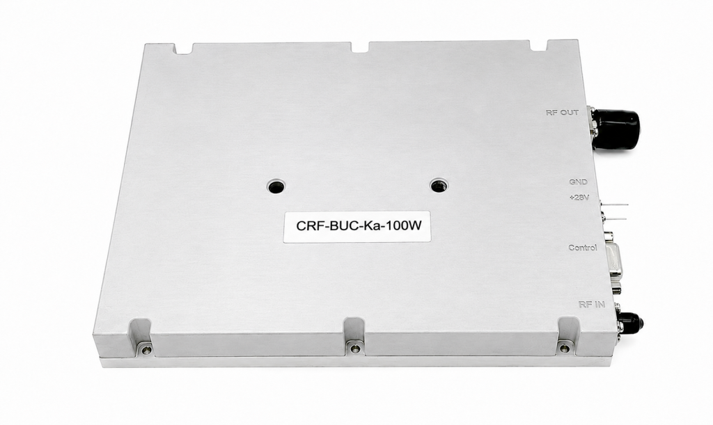
| Parameter | CorelixRF Specification |
| Model | CRF-BUC-Ku-100W |
| RF Frequency | 13.75 / 14 – 14.5 GHz |
| Output Power | ≥50 dBm (100W rated) |
| Weight | 5.5 kg |
| Application Focus | Vehicle / Maritime / VSAT |
We analyzed how low-frequency vibrations in armored chassis destroy generic RF hardware through micro-cracking and flange loosening. We detailed field-tested diagnostic techniques using VNA and spectrum analyzers finding hidden physical faults. The CRF-BUC-Ku-100W provides a structurally hardened solution engineered specifically surviving brutal kinetic environments. System integrators facing deployment failures should consult our technical data immediately. Contact CorelixRF engineering evaluating datasheet parameters securing reliable field performance.
FAQ
Q1: What is the primary cause of intermittent RF failure in tracked vehicles?
Continuous low-frequency vibrations ranging from 10 to 50 Hz create harmonic resonance. This resonance bends PCBs causing microscopic solder joint cracks and loosens threaded RF connections resulting in severe impedance mismatches.
Q2: How does a loose waveguide flange affect BUC performance?
A loose WR75 flange creates a physical gap that alters the reactive impedance at 14 GHz. This gap reflects microwave energy back into the amplifier and triggers VSWR protection circuits.
Q3: Why do we recommend the CRF-BUC-Ku-100W for armored deployments?
This specific model features a CNC milled solid aluminum chassis that mounts heavy components directly to metal rather than fragile PCBs. It utilizes aviation-grade connectors and indium-based solders to survive extreme kinetic shock.
Q4: Can generic commercial BUCs survive 50 Hz track vibrations?
No. Generic units utilize brittle SAC305 solder and rigid FR4 boards that fracture under continuous cyclic strain. Their plastic connectors and weak internal mounts fail rapidly in armored environments.
Q5: What test equipment detects vibrating micro-cracks in the field?
Engineers must use a Vector Network Analyzer set to a continuous Smith Chart sweep. By physically tapping the BUC chassis with a mallet, any internal micro-cracks will manifest as wild jumps in the RF trace.
Authorized RF engineering and compliance review
For regulated RF systems, this page should be used as an engineering and compliance review path, not as a public deployment checklist. CorelixRF starts with authorization status, operating region, frequency plan, output limit, antenna interface, safety controls, thermal limits and acceptance documents.
- RFQ checklist – send the data buyers usually forget, including band, power, duty cycle, interface and test standard
- delivery documentation – check what documents can support incoming inspection, FAT review and long-term maintenance
- quality and certification review – review the quality and compliance evidence before the project moves into procurement
- RF front-end platform – compare the RF chain as a system instead of selecting one isolated module
- RF configurator – turn frequency, power, thermal and interface requirements into a first configuration brief
- case studies – review similar engineering paths before sending an RFQ
- engineering contact – send the application notes, block diagram or target specification to engineering sales
This keeps the discussion inside lawful, authorized RF programs while still giving procurement teams a clear way to request amplifier, antenna, SDR source, documentation and factory review.