
Engineering Decision and RFQ Checklist
This page is now treated as a primary RF engineering guide for vibration, connectors, grounding, thermal drift and rugged acceptance. Use the checklist below to turn the article into a buyer-ready RFQ and factory review package.
| Decision Area | What to Confirm | Evidence to Request |
|---|---|---|
| Operating condition | Band, output power, duty cycle, waveform or sweep condition. | Rated operating table and test setup notes. |
| Interface | RF connector, load or antenna condition, control interface and power supply. | Interface drawing, control table and connector limits. |
| Reliability | Thermal path, protection behavior, enclosure airflow and environmental margin. | Thermal data, protection event notes and inspection records. |
| Acceptance | Gain, flatness, power, mismatch behavior, stability or repeatability limits. | FAT checklist, calibration state and final test curves. |
- RFQ checklist – convert requirements into buyer-ready fields.
- RF configurator – summarize band, power, interface and duty-cycle requirements.
- Delivery documentation – align test curves and FAT-style evidence.
- Case studies – compare how engineering issues become procurement decisions.
- Contact CorelixRF – send the requirement package for review.
Primary Topic Hub and RFQ Path
This primary guide now consolidates related RF engineering references. Use it for the current technical explanation, RFQ preparation, factory review and delivery documentation path.
- How To Prevent Tracked Armor Signal Anomalies At 40GHz? – consolidated reference
The purpose is to reduce duplicate SEO pages while keeping buyers on one stronger engineering guide with clearer RFQ and documentation paths.
- RFQ checklist – prepare band, power, duty cycle, interface, cooling and acceptance inputs.
- RF configurator – turn project requirements into a first engineering brief.
- Delivery documentation – align test curves, inspection records and FAT-style evidence.
- Case studies – review how CorelixRF frames RF problems for buyer decisions.
- Contact engineering sales – submit the documented scope for review.
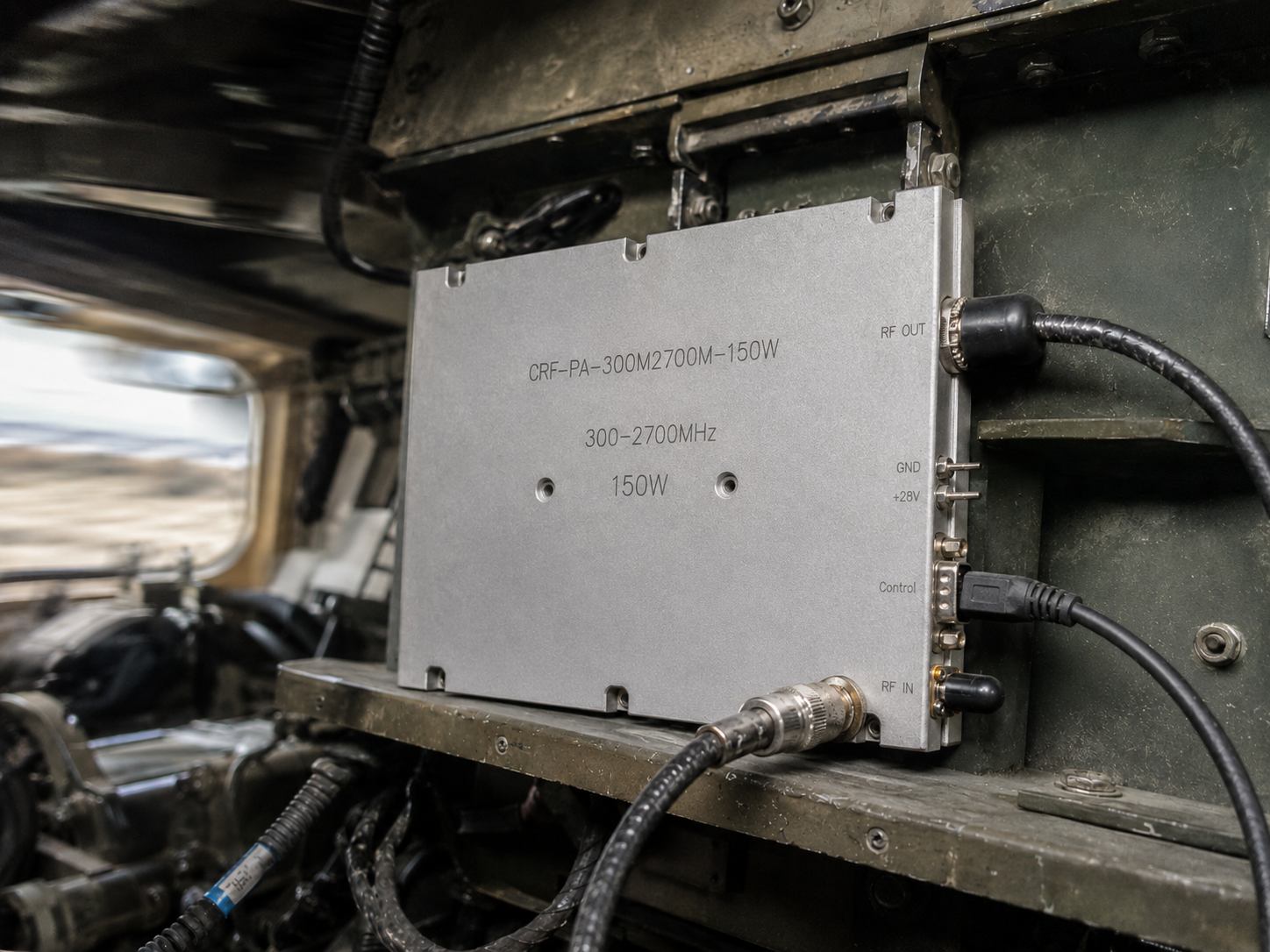
Field Troubleshooting: Diagnosing Tracked Armor Signal Anomalies and Solder Joint Cracking. Tracked armor communication modules face severe mechanical stress during active deployment sequences. Prolonged low-frequency vibration wreaks havoc on internal RF components over extended operational periods. Operators suddenly lose complete situational awareness when transmit power drops without warning mid-mission. These specific tracked armor signal anomalies present massive challenges for frontline repair crews. Continuous mechanical resonance literally shakes internal amplifier structures apart. Here’s the deal: rigorous diagnostic procedures resolve these physical failure modes fast. Integrating our CRF-PA-300M2700M-150W module guarantees permanent reliability under harsh conditions. We engineer all hardware at CorelixRF based purely on verifiable physical truth. This approach eliminates guesswork from military vehicle integration projects. Replacing failing commercial amplifiers with mil-spec designs prevents catastrophic mission failures. Your maintenance technicians need solid data rather than marketing claims. We provide exact methodologies for identifying hidden hardware faults accurately.
1 Field Diagnostics for Tracked Armor Signal Anomalies
Identifying Initial VSWR Alarms
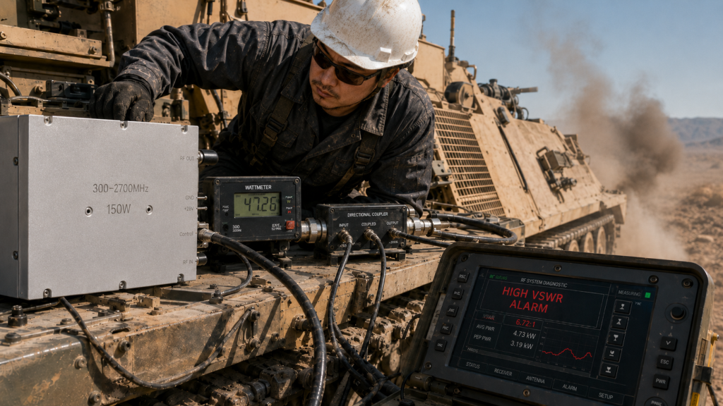
Frontline technicians constantly battle intermittent tracked armor signal anomalies during active maneuvers. Electronic warfare consoles suddenly flash high Voltage Standing Wave Ratio warnings. These critical alerts indicate a severe impedance mismatch within your transmission line. Operators usually reset their systems hoping for an easy software fix. You might be wondering: why do these specific errors disappear when vehicles stop moving completely? Low-frequency engine vibrations cause loose SMA-Female connectors temporarily breaking physical contact. Measuring output power using inline wattmeters reveals massive fluctuations during engine revving. We connect directional couplers directly behind power amplifier output ports. Monitoring forward power drop-offs confirms structural integrity degradation quickly. Our engineers never trust simple software diagnostics for hardware-level physical faults. You must utilize specialized instruments for validating these complex electrical pathways. Field expedient methods often mask underlying mechanical failures temporarily. Proper diagnostics require isolating specific components from broader vehicle subsystems.
Using Oscilloscopes for Low-Frequency Vibration Profiling
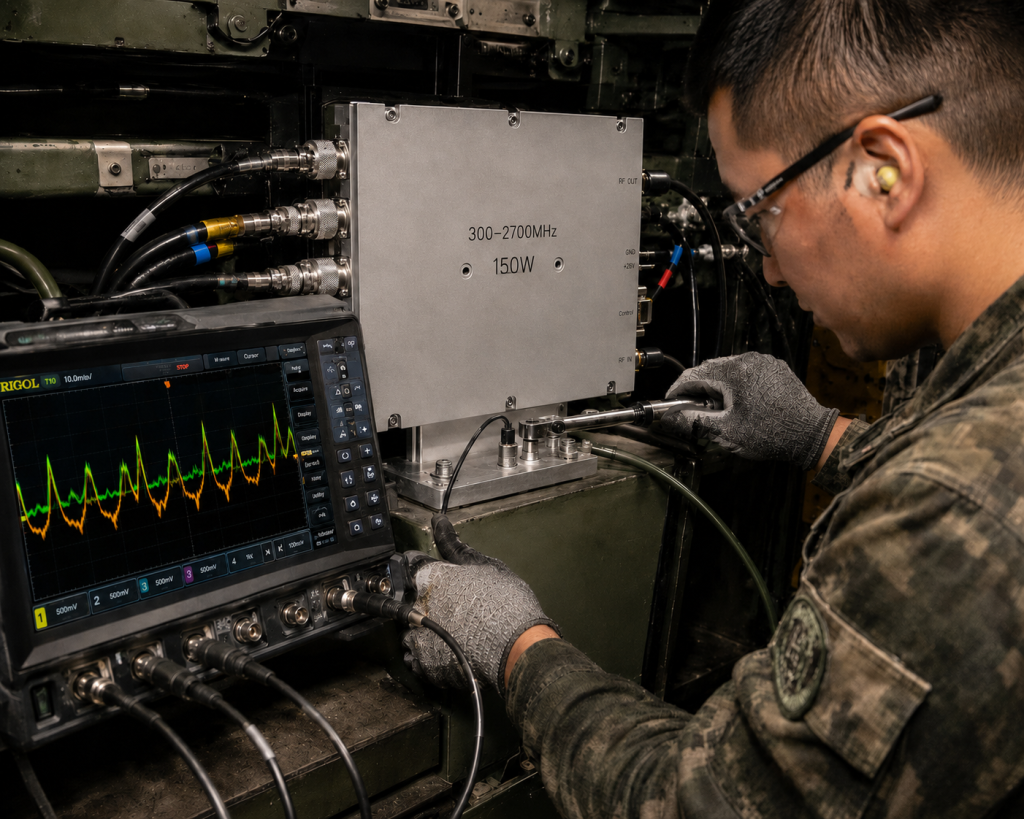
Deploying portable oscilloscopes helps technicians correlate RF dropouts with mechanical shock. We attach specialized vibration sensors adjacent near transmission hardware chassis mounts. Technicians compare mechanical sensor traces against detected envelope signals from RF outputs. A clear visual pattern always emerges matching diesel engine RPM frequencies. These continuous 10 Hz through 50 Hz mechanical waves loosen mounting screws relentlessly. Operators must torque every chassis fastener utilizing properly calibrated mechanical tools. Ignoring this base mechanical reality guarantees subsequent internal amplifier destruction. What’s the real story? Sustained vibration literally changes physical geometries inside waveguide structures. This mechanical deformation alters parasitic capacitances across high-frequency circuit boards. We see specific amplitude modulation appearing on otherwise clean continuous wave signals. Engineers must capture these transient events using deep memory oscilloscope functions. Triggering on envelope voltage drops isolates exact moments of mechanical failure. Replacing affected assemblies remains your only viable long-term operational solution.
VNA Measurements for Solder Joint Degradation
Vector Network Analyzers expose hidden faults inside malfunctioning RF transmission modules. We calibrate our portable VNA units directly at main antenna feedline inputs. Sweeping return loss measurements reveal sudden phase shifts across specific operational bandwidths. A sharp dip in S11 traces indicates internal micro-cracking has occurred. Tracked armor signal anomalies often stem from these completely invisible PCB defects. Evaluating S21 gain parameters shows inconsistent amplification across wide frequency ranges. We replace degraded units immediately upon seeing these specific erratic trace signatures. Connecting a 50-ohm dummy load isolates amplifier hardware from antenna variables. Our field teams record S-parameter files for later laboratory comparative analysis. Tracking these specific degradation curves helps predict future hardware failure rates accurately. Replacing standard commercial units with hardened military hardware stops this failure cycle. You cannot patch microscopic solder fractures using standard field repair techniques.
Field Diagnostic Parameters
| Diagnostic Tool | Target Measurement | Failure Indication | Required Action |
| Inline Wattmeter | Forward/Reflected Power | High VSWR or power drop | Check N-Female RF output connectors |
| Portable Oscilloscope | Envelope Detection | Signal dropouts matching vibration | Torque chassis mounting screws |
| Vector Network Analyzer | S11 Return Loss | Phase shifts and impedance jumps | Replace entire RF amplifier module |
2 The Physics of Vibration-Induced RF Failures
Connector Loosening Under Tracked Armor Strain
Mechanical resonance acts as a destructive force against rigid coaxial interfaces. Tracked armor traverses rocky landscapes generating massive kinetic energy transfer directly. This severe kinetic energy flows straight through standard equipment mounting brackets. Threaded SMA connections lack sufficient friction for maintaining torque under continuous shaking. Here is the kicker: slight rotational loosening creates massive electrical discontinuities instantly. An unseated center pin introduces series capacitance altering system impedance drastically. This sudden impedance mismatch causes high reflected power damaging output transistors. We observe carbon tracking on connector dielectrics indicating internal RF arcing. Commercial off-the-shelf amplifiers utilize cheap brass housings expanding under thermal loads. This thermal expansion compounds baseline vibration loosening issues during summer deployments. Upgrading your hardware demands utilizing modules featuring robust mechanical interface designs. CorelixRF specifies precise torque values guaranteeing connector stability across harsh deployments.
Microscopic Solder Joint Cracking Mechanisms
Surface-mounted power transistors endure immense sheer forces during off-road vehicle transit. Heavy copper flanges act like microscopic hammers against soft solder joints. Repeated flexing of underlying FR4 or Rogers substrates accelerates material fatigue. We analyze failed commercial units using industrial X-ray inspection equipment routinely. These scans reveal hairline fractures propagating through entire lead-free solder fillets. Tracked armor signal anomalies trace back directly towards these invisible structural failures. Ready for the good part? Proper metallurgical engineering solves this specific manufacturing defect entirely. CorelixRF utilizes specialized high-lead solder alloys designed for extreme military environments. These specific alloys offer superior ductility absorbing mechanical shock waves harmlessly. Void-free soldering processes guarantee maximum contact area transferring both heat and RF energy. Rigid quality control ensures every internal bond withstands severe tracked deployment profiles. Our manufacturing facility implements strict temperature profiles during automated reflow operations.
Thermal Expansion Compounding Mechanical Stress
Temperature fluctuations exacerbate existing mechanical vulnerabilities inside standard RF hardware enclosures. Desert deployments force aluminum chassis structures expanding significantly during midday heat. Nighttime cooling causes rapid contraction placing massive sheer stress on internal PCB mounts. This continuous thermal cycling creates microscopic friction between dissimilar conductive materials. Ground planes separate from metal housings causing erratic parasitic inductance values. These changing parasitic elements degrade overall amplifier stability causing spurious emissions. Spurious signals must remain ≤-60 dBc per stringent military specifications. Uncontrolled harmonic generation wastes DC power while jamming friendly adjacent receivers. We maintain strict harmonics limits between -12 and ≤-10 dBc. Properly engineered thermal interfaces mitigate these destructive physical movement cycles effectively. CorelixRF engineers employ matched thermal expansion materials resolving these complex physical interactions. Your systems demand hardware designed specifically for surviving these brutal realities.
Material Failure Modes
| Stress Factor | Affected Component | Physical Result | Electrical Symptom |
| Low-Frequency Vibration | SMA/N Connectors | Thread loosening | Intermittent signal drops |
| Mechanical Shock | Transistor Solder Joints | Hairline fractures | Phase shifts / Gain loss |
| Thermal Cycling | PCB Ground Planes | Substrate delamination | Increased spurious emissions |
3 Evaluating the CRF-PA-300M2700M-150W Architecture
300-2,700 MHz Wideband Hardware Validation
Modern electronic warfare platforms require vast frequency coverage hunting diverse hostile signals. Our engineers developed a monolithic solution covering 300-2,700 MHz continuously. This massive bandwidth eliminates needing multiple narrowband amplifiers cluttering cramped vehicle interiors. We achieve flat gain profiles measuring ≤1.5 dB across all frequencies. This is where it gets interesting… maintaining such flatness under vibration requires genius engineering. Standard commercial amplifiers exhibit wild gain ripples when subjected against mechanical shock. CorelixRF utilizes advanced broadband matching networks etched directly onto rigid substrates. These fixed planar structures cannot vibrate loose unlike hand-wound wire inductors. You receive predictable amplification performance regardless of external terrain roughness factors. A typical gain of 52 dB ensures weak exciter signals reach full power. We guarantee a minimum 51 dB gain across worst-case environmental conditions. System integrators rely on these hard numbers for calculating exact link budgets.
150W Output Power Stability Under Vibration
Delivering consistent RF energy remains paramount for successful jamming or communication missions. The CRF-PA-300M2700M-150W guarantees 150 W of rated output power reliably. We utilize ruggedized LDMOS transistors providing CW or Saturated power modes. Tracked armor signal anomalies often manifest as sudden output power collapse. Our design incorporates robust bias tracking networks compensating for transient thermal spikes. These networks maintain steady transistor operating points during heavy weapon firing shocks. Generating 150 watts requires driving input signals between 0 and 8 dBm. We test every module against severe mechanical drop tests before factory shipment. You never worry about internal component shifts degrading total output wattage. Our engineering team prioritizes physical resilience over simple benchtop laboratory performance metrics. Real-world deployments demand hardware operating perfectly while covered in dust and mud.
VSWR Tolerance and Protection Circuits
Antenna systems mounted on tracked vehicles suffer constant physical battering from obstacles. Branches and debris bend antenna elements altering tuned resonant frequencies constantly. This physical damage creates massive reflected energy flowing backward into amplifier modules. Our architecture tolerates severe output VSWR conditions measuring ≤2.0:1 safely. What’s the catch? Standard amplifiers incinerate themselves facing similar high reflected power scenarios. CorelixRF integrates ultra-fast hardware protection loops monitoring reverse power levels continuously. These analog circuits react micro-seconds faster than software-based polling mechanisms ever could. We maintain excellent input VSWR measuring ≤1.5:1 preventing exciter stage damage. Typical input match performance hovers around a very stable 1.3:1 ratio. Your entire RF chain remains safe despite catastrophic external antenna strikes. Relying on verifiable hardware protection guarantees mission survival during chaotic combat operations.
RF Performance Metrics
| Parameter | Minimum | Typical | Maximum |
| Frequency Range | 300 MHz | – | 2,700 MHz |
| Output Power | 150 W | 150 W | – |
| Gain Flatness | – | – | ≤1.5 dB |
| Input VSWR | – | 1.3:1 | ≤1.5:1 |
4 Structural Integration for Tracked Armor Environments
Analyzing the 200x158x25 mm Package Size
Space constraints dictate hardware selection processes inside cramped modern combat vehicles. Our engineering team prioritized volumetric efficiency without sacrificing internal component spacing. The resulting package size measures exactly 200 x 158 x 25 mm. This ultra-low 25 mm profile allows mounting directly behind standard equipment racks. Here is the deal: bulky legacy amplifiers waste precious internal cabin volume. We milled this chassis from solid aircraft-grade aluminum blocking ensuring extreme rigidity. A total weight measuring ≤1.4 kg minimizes stress on bulkhead mounting points. Lighter modules experience significantly lower kinetic forces during violent vehicular maneuvers. We provide a fully visible mechanical drawing for easier dimensional review. System integrators use these precise dimensions for fabricating custom shock-absorbing mounting trays. Proper physical integration represents your first defense against tracked armor signal anomalies. We deliver physical hardware matching our published mechanical specifications perfectly every time.
Securing SMA-Female and N-Female Connectors
Connector failure remains a primary culprit behind intermittent field communication blackouts. We utilize a ruggedized SMA-Female connector for all RF input signals. This interface accepts flexible coaxial cables routing from central electronic warfare controllers. For high-power output transmission, we specify a massive N-Female bulkhead connector. You might be wondering: why avoid newer lightweight connector formats entirely? N-type connectors feature robust threaded coupling mechanisms resisting violent mechanical separation forces. These massive brass housings dissipate localized heat generated by 150W continuous waves. We secure these connectors directly into thick aluminum chassis walls preventing flexion. Internal coaxial leads feature stress-relief loops decoupling external vibrations from fragile PCBs. Operators must inspect these specific physical junctions during routine vehicle maintenance sweeps. Utilizing proper torque wrenches prevents under-tightening which causes immediate signal degradation. CorelixRF designs physical interfaces built specifically for surviving decades of military abuse.
DB9 Control Interface Reliability
Monitoring amplifier health requires robust digital and analog telemetry data streams. We integrated a classic DB9 connector handling all control interface requirements. This legacy standard provides unmatched physical security utilizing dual captive mounting screws. Flimsy USB or Ethernet jacks simply vibrate loose inside roaring diesel environments. The DB9 interface transmits forward power readings and internal temperature analog voltages. System controllers utilize this data for managing overall vehicle power distribution intelligently. We route these sensitive telemetry lines away from noisy internal RF sections. This physical isolation prevents high-power microwave energy from corrupting digital diagnostic signals. Tracked armor signal anomalies often trigger false alarms on unshielded control cables. Our heavily filtered DB9 port rejects external electromagnetic interference completely during operations. You gain absolute confidence viewing telemetry data matching actual physical hardware states.
Mechanical Dimensions
| Feature | Specification | Material/Type |
| Package Size | 200 x 158 x 25 mm | Milled Aluminum |
| Total Weight | ≤1.4 kg | Solid Block Housing |
| RF Input | SMA-Female | Stainless/Brass |
| RF Output | N-Female | Rugged Brass |
5 Power Supply and Thermal Management Strategies
28 VDC Supply Voltage Stability
Military vehicles utilize massive diesel alternators generating inherently dirty electrical power. Huge voltage spikes occur whenever operators engage heavy turret traverse electric motors. Our amplifier requires a nominal 28 VDC supply voltage for optimal performance. We engineered internal voltage regulators handling massive transient input power surges easily. This is where it gets interesting poor power conditioning destroys RF transistors instantly. Standard commercial amplifiers lack sufficient input capacitance for smoothing brutal vehicular transients. CorelixRF integrates heavy-duty pi-filters directly behind DC power input terminals. These filters block high-frequency alternator whine from contaminating clean RF output signals. Maintaining stable 28 VDC bias lines ensures your gain remains completely flat. Tracked armor signal anomalies frequently originate from these overlooked power supply fluctuations. We demand clean power delivery for generating pristine microwave energy reliably. Upgrading your vehicle power distribution units prevents random amplifier resets during combat.
Managing Current Consumption
Generating massive RF power demands significant DC electrical current pulling capacity. The CRF-PA-300M2700M-150W limits maximum current consumption measuring ≤20 A safely. This predictable current draw prevents overloading centralized vehicular power distribution breakers. We utilize highly efficient LDMOS devices converting DC energy into RF effectively. High efficiency means less wasted power converting directly into unwanted thermal heat. Ready for the good part? Lower current draw extends battery life during engine-off silent watch operations. Operators appreciate retaining communication capabilities without running noisy diesel generators constantly. We specify thick gauge wiring harnesses for handling continuous 20 A loads. Undersized cables cause massive voltage drops starving RF transistors during peak demand. Our field engineers frequently troubleshoot installations featuring inadequate DC power wiring practices. You must calculate voltage drops accurately ensuring full 28 VDC reaches the module.
Air Cooling Implementation and Chassis Heatsinking
Dissipating excess heat determines absolute maximum lifespan for any solid-state amplifier. Our engineers selected an air cooling method for maximizing deployment flexibility. Liquid-cooled systems introduce massive complexity and fatal leak risks inside armored vehicles. We designed massive extruded aluminum fins along the entire chassis bottom plate. These fins maximize surface area transferring heat into ambient cabin air quickly. Tracked armor signal anomalies escalate rapidly when internal junction temperatures exceed limits. We mandate operating within a strict -40 to +85 °C temperature range. The 85 °C upper limit provides massive thermal headroom for desert operations. You must provide adequate forced airflow across these cooling fins during installation. Stacking multiple amplifiers together without spacing causes catastrophic thermal runaway failure cascades. CorelixRF provides detailed thermal modeling data helping integrators design optimal cooling shrouds.
Power and Thermal Specs
| Parameter | Value | Critical Installation Note |
| Supply Voltage | 28 VDC | Use heavy-duty transient suppression |
| Current Consumption | ≤20 A | Requires thick gauge DC wiring |
| Cooling Method | Air Cooling | Provide forced airflow across fins |
| Operating Temp | -40 to +85 °C | Avoid stacking without air gaps |
6 Compliance and Long-Term Reliability Testing
GJB 9001C and ISO 9001 Standards
Procurement engineers demand verifiable proof regarding manufacturing quality and consistency. CorelixRF operates under strict ISO 9001 quality management framework guidelines continuously. We also maintain full compliance regarding rigorous GJB 9001C military manufacturing standards. What’s the real story? Paper certificates mean nothing without grueling physical validation. We track every single component back towards its original silicon foundry source. This extreme traceability prevents counterfeit parts from compromising your critical communication systems. Tracked armor signal anomalies often result from utilizing substandard gray-market electronic components. Our automated optical inspection machines verify every single solder joint flawlessly. We maintain comprehensive documentation detailing exact torque specifications for every assembled chassis. You receive identical performance characteristics whether buying one unit or one thousand. System integrators trust our strict adherence towards verifiable military quality control processes.
Extreme Temperature Operations
Combat vehicles deploy across diverse geographical theaters facing brutal climate extremes. We test amplifiers operating continuously at -40 °C simulating arctic winter conditions. Cold temperatures cause standard PCB substrates shrinking rapidly snapping fragile ceramic capacitors. Our hardware survives these brutal cold-soak periods delivering full power upon activation. Conversely, we bake units at +85 °C simulating closed-cabin desert heat. Storage temperature limits match operating limits precisely spanning -40 to +85 °C. Here is the kicker: thermal cycling destroys weak engineering designs very fast. We execute rapid thermal shock tests forcing components expanding and contracting violently. This aggressive testing identifies latent metallurgical defects long before factory shipment occurs. Our robust environmental hardening guarantees your systems function perfectly regardless of weather. CorelixRF designs microwave modules conquering Earth’s most unforgiving combat environments effortlessly.
Verifying MTBF in Harsh RF Environments
Mean Time Between Failures data dictates logistical supply chain planning requirements. We provide detailed MTBF reliability data available on request for specific projects. CorelixRF engineering teams can provide feasibility reviews within 48 hours rapidly. We bombard prototypes with massive random vibration profiles matching tracked vehicle signatures. Environmental and validation data can be supplied for project review where applicable. Integrators require this hard data for satisfying stringent defense contractor procurement mandates. Custom frequency bands or control interfaces are available matching unique system requirements. Our RoHS compliant designs ensure long-term availability avoiding hazardous material regulatory bans. We maintain CE and FCC certifications ensuring global deployment legality unconditionally. Partnering with CorelixRF guarantees you deploy hardware engineered for absolute survival.
Compliance Framework
| Standard / Metric | Scope | Relevance to Tracked Armor |
| GJB 9001C | Military Quality | Ensures consistent robust manufacturing |
| ISO 9001 | Quality Management | Guarantees component traceability |
| RoHS / CE / FCC | Regulatory Compliance | Global deployment legality |
| MTBF Data | Reliability | Predicts maintenance schedules |
Tracked armor signal anomalies originating from vibration-induced connector loosening demand rugged hardware solutions. The CRF-PA-300M2700M-150W delivers unwavering 150W performance across 300-2,700 MHz, surviving extreme physical abuse. Stop relying on fragile commercial amplifiers for critical combat systems. Contact the CorelixRF engineering team today to request MTBF data and fully evaluate this ruggedized module.
FAQ Section
- Q1: What is the frequency range of the CRF-PA-300M2700M-150W?
- The amplifier covers a continuous wideband frequency range spanning 300-2,700 MHz.
- Q2: How does the module handle high VSWR conditions?
- It tolerates a maximum output VSWR of ≤2.0:1 safely without suffering transistor damage.
- Q3: What power supply specifications does this amplifier require?
- The unit requires a 28 VDC supply voltage with a maximum current consumption measuring ≤20 A.
- Q4: What are the operating temperature limits for field deployment?
- This module guarantees reliable operation across an extreme temperature range spanning -40 to +85 °C.
- Q5: What physical RF connectors are used on this model?
- It utilizes a rugged SMA-Female connector for RF input and a robust N-Female connector for RF output.
Authorized RF engineering and compliance review
For regulated RF systems, this page should be used as an engineering and compliance review path, not as a public deployment checklist. CorelixRF starts with authorization status, operating region, frequency plan, output limit, antenna interface, safety controls, thermal limits and acceptance documents.
- RFQ checklist – send the data buyers usually forget, including band, power, duty cycle, interface and test standard
- delivery documentation – check what documents can support incoming inspection, FAT review and long-term maintenance
- quality and certification review – review the quality and compliance evidence before the project moves into procurement
- RF front-end platform – compare the RF chain as a system instead of selecting one isolated module
- RF configurator – turn frequency, power, thermal and interface requirements into a first configuration brief
- case studies – review similar engineering paths before sending an RFQ
- engineering contact – send the application notes, block diagram or target specification to engineering sales
This keeps the discussion inside lawful, authorized RF programs while still giving procurement teams a clear way to request amplifier, antenna, SDR source, documentation and factory review.