
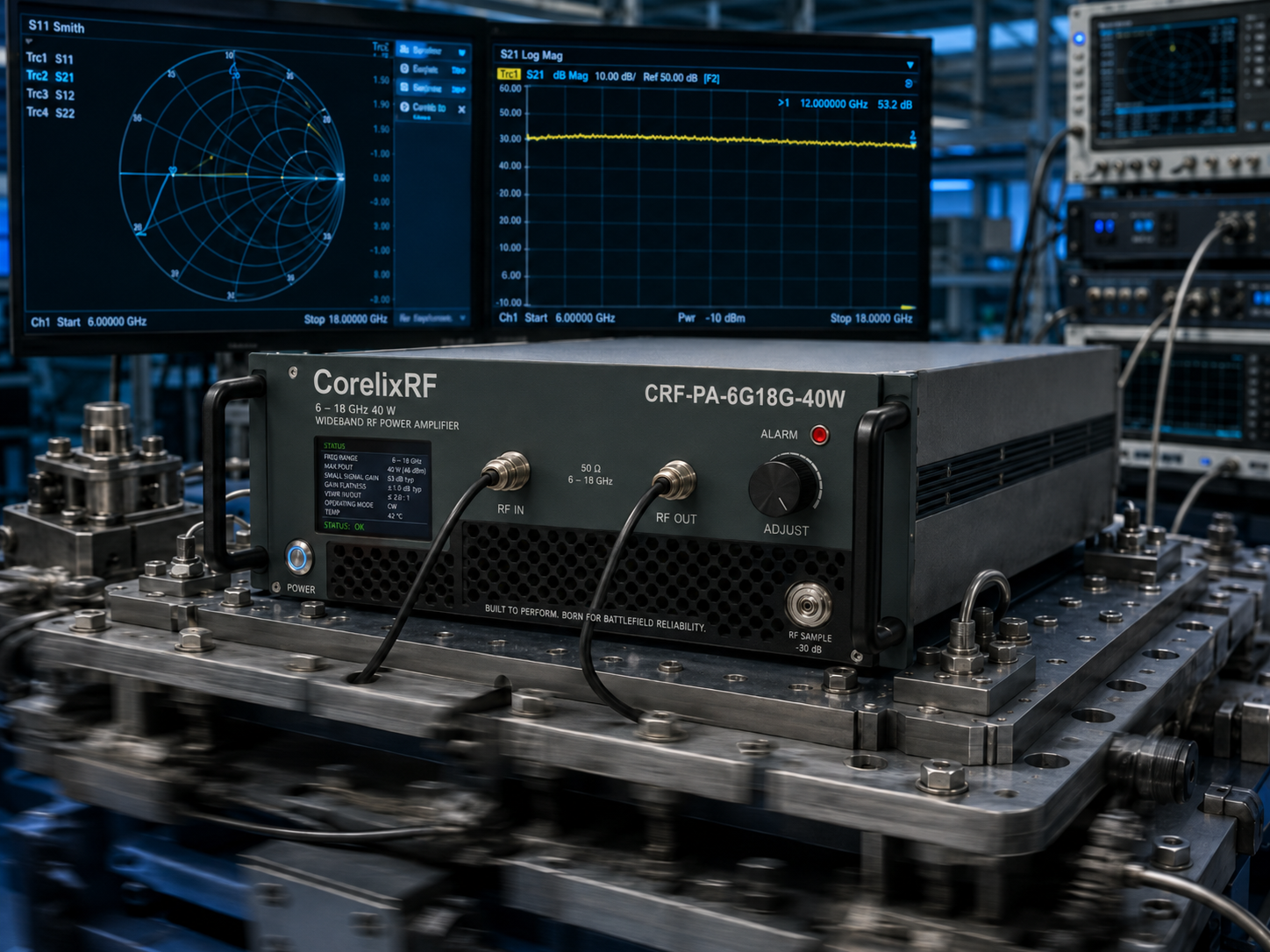
Identify problem: Tracked armored vehicles constantly generate brutal low-frequency kinetic vibrations that systematically destroy commercial RF amplifier architectures. Present solution: Ruggedizing specific 19-inch 3U rack-mounted GaN systems with reinforced interconnects prevents devastating field failures. Establish trust: Having spent two decades diagnosing RF power stage failures in military motor pools, I know exactly why standard laboratory equipment crumbles inside a steel hull.
1. Why Do Tracked Armors Destroy RF Amplifier Architectures?
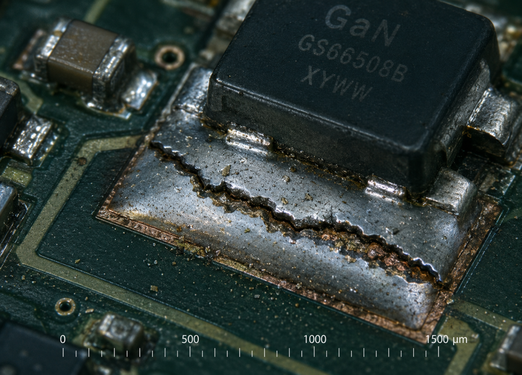
Tracked armors inflict relentless kinetic stress on electronic payloads through continuous low-frequency mechanical vibration. Those heavy steel treads slapping against hard terrain create aggressive harmonic oscillations. Here is the deal, typical RF power amplifiers rely heavily on rigid surface-mount matching networks. Standard commercial off-the-shelf equipment simply assumes a static operating environment. When integrators bolt standard enclosures directly into vehicle racks, catastrophic mechanical failure becomes inevitable. Heavy components begin resonating at specific chassis frequencies. This physical resonance aggressively twists internal circuit boards against their mounting standoffs. Over hundreds of operational hours, microscopic cracks propagate through lead-free solder joints securing sensitive gallium nitride transistors. Field engineers frequently observe sudden output power drops or erratic spectrum analyzer traces during routine maintenance checks. You will notice high-frequency gain collapsing completely because fractured traces introduce massive impedance mismatches. Without strict architectural reinforcement at both macro and micro levels, your electronic warfare module simply becomes useless dead weight inside that armored hull.
The harsh reality of low-frequency chassis vibration
Mechanically induced stress specifically targets dense component clusters located near structural mounting points. Continuous rumbling translates directly into lateral sheer forces across large ceramic capacitors.
Microscopic solder joint fatigue over continuous operation
Thermomechanical fatigue heavily compounds pure kinetic damage within enclosed spaces. Repeated heating cycles during RF transmission weaken solder alloys right before violent physical shocks shatter them completely.
| Parameter | Typical Commercial Standard | Tracked Armor Requirement |
| Vibration Tolerance | Minimal lab environment | Continuous 10-50 Hz high amplitude |
| Solder Joint Strain | Static thermal expansion | Complex thermomechanical shear |
| Component Mounting | Standard PCB standoffs | Dampened sub-chassis isolation |
| Chassis Rigidity | Standard aluminum sheet | Thick milled structural brackets |
2. What Causes RF Connectors to Fail Under Constant Kinetic Stress?
Coaxial connectors serve as primary failure points when integrated into moving metallic platforms. The input and output N-F connectors specified for broadband systems absorb tremendous physical strain from thick coaxial cables. What is the real story? Installers often use heavy corrugated copper cables lacking adequate strain relief loops. Constant chassis bouncing forces these stiff cables to violently leverage against the amplifier bulkhead. This relentless mechanical prying action slowly loosens the threaded N-type coupling nuts. Once a connector loses strict mating torque, the center pin contact resistance fluctuates wildly during vehicle motion. Intermittent electrical contact instantly generates severe voltage standing wave ratio spikes. Reflected RF energy bounces back into the final amplifier stages. Operators staring at their electronic countermeasures console suddenly see flashing red fault indicators as internal protection circuits trip. We constantly find severely degraded center pins displaying microscopic arcing burns during post-incident teardowns. Proper architecture demands meticulous attention regarding how external cable wiring harnesses interface mechanically with fixed bulkhead ports.
Coaxial connector loosening and VSWR mismatch loops
Loose threaded interfaces drastically alter precise 50-ohm characteristic impedances required for microwave transmission. Resulting impedance bumps create resonant cavities that severely distort wideband frequency responses.
System-level diagnostics when the N-F interface shifts
Vector network analyzers will display distinct Smith chart anomalies resembling erratic circular loops. These specific trace artifacts confirm physical connector degradation rather than internal semiconductor faults.
| Connector Type | Interface Vulnerability | Mitigation Strategy |
| Input: N-F | Center pin friction loss | Right-angle adapters with locking wire |
| Output: N-F | Thread loosening under shock | Calibrated torque wrenches plus vibration damping |
| RS485 / LAN | Pin fretting corrosion | Ruggedized circular military equivalents |
| AC Power | Plug backing out | Securing brackets for heavy cords |
3. How Does the CRF-PA-6000M18000M-40W Resolve Mechanical Breakdown?
CorelixRF engineers engineered the CRF-PA-6000M18000M-40W specifically targeting extreme environmental deployment scenarios. Operating seamlessly across a massive 6 – 18 GHz frequency range demands extraordinary mechanical stability. This is where it gets interesting, the entire chassis utilizes a robust 19-inch 3U package designed explicitly for heavy rack integration. Internal gallium nitride technology provides exceptional power density while reducing overall thermal mass. Our design methodology strictly isolates sensitive high-frequency microstrip networks from external kinetic forces. Thick aluminum baseplates secure active GaN devices using precisely torqued fasteners and specialized compliant thermal interface materials. This specific mechanical layout dampens aggressive low-frequency vibrations before they reach fragile ceramic matching networks. Furthermore, the RF connectors (Input: N-F, Output: N-F) feature heavy-duty flange mounting systems bolted directly into the primary structural frame. This architecture completely transfers external cable strain away from the internal printed circuit boards. It effectively prevents those devastating solder joint fractures we discussed earlier.
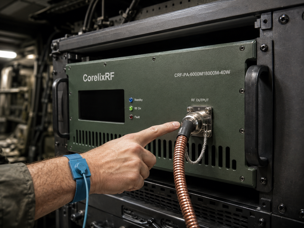
Structural reinforcement for the 19-inch 3U package
Heavy gauge metalwork prevents chassis flex when armored vehicles traverse rugged off-road terrain. Strategic internal cross-bracing severely limits large printed circuit boards from acting like acoustic drumheads.
Integrating advanced GaN technology with ruggedized layouts
Advanced GaN technology allows fewer amplification stages compared to older gallium arsenide designs. Fewer components inherently drastically reduce total statistical failure probabilities under severe shock conditions.
| CorelixRF Specification | Rated Value | Engineering Implication |
| Frequency Range | 6 – 18 GHz | Broad coverage requires absolute dimensional stability |
| Rated Output Power | 40 W | Substantial thermal load needs secure heatsinking |
| Package Size | 19″, 3U | Standard rack mount requires front/rear rail support |
| RF Connectors In/Out | Input: N-F, Output: N-F | Mechanically strong but requires external strain relief |
4. Are VSWR Protection Mechanisms Sufficient for Tracked Vehicles?
Relying exclusively upon electronic VSWR protection circuits remains a dangerous gamble for military integrators. When an antenna gets sheared off by a low-hanging tree branch, reflected power levels spike instantaneously. The CRF-PA-6000M18000M-40W includes built-in protection against over-voltage, over-temperature, over-drive, and VSWR. You might be wondering, can software algorithms react fast enough to save the final amplifier transistors? CorelixRF implemented ultra-fast analog detection loops alongside digital monitoring via RS485 and LAN interfaces. However, true engineering practice dictates that physical robustness must precede electronic intervention. If low-frequency vibration slowly loosens an antenna feedline, the VSWR creeps up gradually. The system maintains an input VSWR of 2.0:1 maximum. Operating continuously at elevated reflection coefficients generates excessive localized heating within the GaN device package. Solid architecture involves pairing this amplifier with equally ruggedized interconnects featuring locking mechanisms. Built-in protection acts as your final safety net rather than a substitute for competent mechanical integration.
Overcoming reverse power reflections during antenna whip
Violent vehicle maneuvers cause tall external antennas to whip violently back and forth. This physical bending dynamically alters antenna impedance properties creating instantaneous mismatch scenarios.
Built-in VSWR protection specifics
Our integrated directional couplers constantly sample forward and reverse microwave power levels. High-speed comparators instantly throttle bias voltages if reflected energy exceeds pre-determined safe thresholds.
| Protection Type | Trigger Condition | System Response |
| Over-voltage | Power Supply anomalies | Shuts down main DC rails |
| Over-temperature | Exceeding 50℃ operating limit | Throttles RF drive or disables bias |
| Over-drive | Input power exceeding 0 dBm | Attenuates small signal gain |
| VSWR | Severe output mismatch | Rapid output power foldback |
5. How to Optimize Link Budgets for 6-18 GHz Jamming Systems?
Designing robust link budgets across ultra-wide bandwidths requires meticulous attention to insertion losses. The 6-18 GHz spectrum suffers severe attenuation through long coaxial cable runs. The CRF-PA-6000M18000M-40W delivers 46 dB of small signal gain with an adjustable gain range of 20 dB. Ready for the good part? This massive gain overhead allows systems engineers significant flexibility when compensating for lossy passive components. You must carefully calculate expected cable losses factoring in temperature extremes. A cable measuring perfectly inside an air-conditioned laboratory will exhibit substantially higher attenuation out in a baking desert environment. The amplifier guarantees a gain flatness of ±4 dB across its entire operating band. Integrators must equalize their driving signals appropriately to ensure maximum 40W rated output power across all frequencies. Neglecting proper drive level equalization often results in heavily distorted output spectra. You will typically see severe harmonic content exceeding the specified -15 to -8 dBc range if driven incorrectly.
Accounting for gain flatness and continuous 40W output
Wideband systems inherently exhibit varying amplification efficiency depending upon the specific frequency utilized. Engineers routinely deploy active slope equalizers preceding the power stage addressing these natural physics limitations.
Cooling and power distribution in cramped armor racks
The equipment utilizes built-in air cooling mechanisms requiring adequate ventilation clearances. Stuffing this 3U chassis inside tightly sealed compartments severely restricts necessary ambient airflow.
| Parameter | CorelixRF Specification | Link Budget Impact |
| Small Signal Gain | 46 dB | Requires very low drive levels |
| Adjustable Gain | 20 dB | Facilitates fine-tuning system output |
| Gain Flatness | -4 to 4 dB | Demands careful input signal leveling |
| Input Power | 0 dBm Max | Exceeding this destroys input stages |
6. What System-Level Integration Tactics Work for RS485 and LAN?
Modern warfare platforms rely absolutely upon continuous telemetry monitoring and remote control capabilities. The CRF-PA-6000M18000M-40W provides comprehensive control interfaces via RS485 and LAN connections. But here is the kicker, standard ethernet RJ45 connectors vibrate loose almost immediately inside armored troop carriers. Experienced integrators immediately cut off commercial plastic connectors replacing them with mil-spec circular threaded equivalents. You must maintain continuous communication with the amplifier verifying internal temperatures and operational status. Optional customization includes forward/reverse power monitoring alongside GPIB control interfaces. Running long data cables alongside high-power RF transmission lines invites disastrous electromagnetic interference issues. Shielded twisted pair wiring remains completely mandatory for RS485 networks operating near 40W microwave emitters. Ground loops will quickly destroy sensitive differential transceivers if you fail isolating different chassis potentials properly. We constantly receive field reports regarding mysterious communication drops traced directly back towards improper grounding schemes.
Maintaining reliable telemetry through hardened interfaces
Digital command packets become easily corrupted by strong local electromagnetic fields generated during transmission. Implementing robust error correction protocols ensures critical shutdown commands penetrate through heavy background noise.
Remote monitoring of internal temperatures and drive levels
Continuous polling of device health metrics allows commanders predictive maintenance insights before catastrophic failures. Graphing internal temperature trends helps identify slowly degrading ventilation fans hidden deep inside racks.
7. Why is Component Selection the Ultimate Trap for Integrators?
Procurement departments frequently attempt substituting cheaper commercial grade cables seeking lower bill-of-materials costs. This practice invariably leads directly toward catastrophic system failures during field deployments. CorelixRF strictly designs equipment utilizing advanced GaN technology meeting CE, FCC, ISO 9001, and GJB 9001C compliance frameworks. Let us dig deeper, cheap commercial cables feature soft dielectric materials which deform under continuous kinetic pressure. When a cable physically squishes, its characteristic impedance changes dramatically. This impedance shift throws off your entire 6-18 GHz matching network. The amplifier’s noise floor rests quietly at -40 dBm/MHz while spurious emissions remain below -60 dBc. Installing poorly shielded cheap components immediately degrades these excellent specifications. External interference easily penetrates weak cable braiding elevating system noise floors unacceptably. You cannot achieve reliable test, measurement, communication, interference, or aviation control applications using compromised interconnects. Professional engineering dictates spending necessary budget acquiring verified ruggedized accessories.
Commercial off-the-shelf vs. military-grade ruggedization
Commercial markets prioritize low manufacturing costs utilizing automated assembly techniques optimized for stationary indoor usage. Ruggedized equipment requires intensive manual inspection processes ensuring every single sub-assembly withstands brutal punishment.
The reality of thermal cycles combined with kinetic shock
Materials expand differently based upon their specific thermal expansion coefficients during operational heating phases. Adding severe mechanical vibration creates a destructive synergy rapidly tearing dissimilar metallic junctions apart.
8. How to Verify Tracked Armor RF Reliability in the Lab?
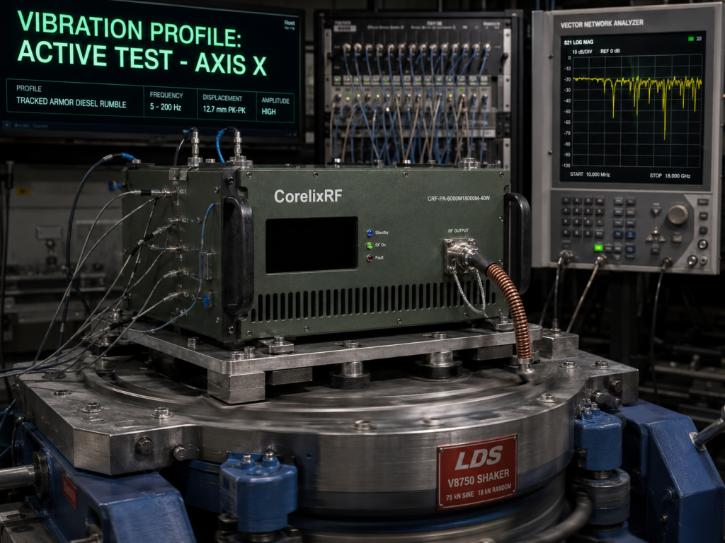
You cannot simply plug a power cord in and declare an amplifier ready for battlefield deployment. Proper verification requires aggressively simulating harsh operational realities inside controlled laboratory environments. The device operates across temperatures ranging from 0 to 50 ℃ utilizing standard AC 220V±10%, 50/60Hz power supplies. You might ask yourself, how do we replicate a diesel engine using test benches? Engineers mount the 19-inch 3U package onto programmable electrodynamic shaker tables. We run continuous swept sine and random vibration profiles matching recorded vehicle chassis telemetry. Simultaneously, we monitor the N-F RF In/Out connectors analyzing forward transmission characteristics using high-speed vector network analyzers. Any microscopic internal solder joint failure instantly registers as sudden jagged dropouts along the S21 gain curve. You must constantly monitor the RS485 / LAN control interface ensuring telemetry does not drop during violent shaking. Only after surviving these grueling multidimensional stress tests can we guarantee reliability.
Simulating the diesel engine rumble on the vibration table
Engineers utilize recorded accelerometer data gathered directly from moving armored vehicles establishing accurate test profiles. These specialized profiles concentrate kinetic energy exactly within those destructive low-frequency bands causing maximum damage.
Interpreting spectrum analyzer noise floors during stress tests
Vibration easily induces microphonic effects inside certain microwave components generating unwanted phase noise. Watching broadband noise floors elevate during physical shaking highlights marginal internal grounding connections requiring immediate redesign.
9. What are the Long-Term Maintenance Protocols for 40W GaN Amplifiers?
Deploying sophisticated GaN microwave technology requires establishing rigid preventative maintenance schedules ensuring longevity. The CRF-PA-6000M18000M-40W relies strictly upon active air cooling mechanisms dissipating substantial thermal energy. Truth be told, armored vehicles operate within incredibly dusty environments quickly clogging intake filters. Reduced airflow forces internal operating temperatures rapidly toward the 50 ℃ absolute maximum limit. Maintenance technicians must routinely pull these 3U chassis units from their racks performing thorough compressed air blowouts. Furthermore, you must continuously inspect those critical N-F RF connectors looking for subtle signs of mechanical fretting. Vibration causes microscopic metal transfer between mating surfaces eventually destroying electrical continuity. We strongly recommend routinely replacing heavy external coaxial cables annually regardless of their apparent visual condition. This proactive replacement strategy drastically reduces unexpected VSWR alarms tripping during critical jamming operations. Ignoring these harsh environmental realities guarantees a drastically shortened operational lifespan.
Air cooling considerations in dusty, high-vibration enclosures
Cooling fans possess rotating bearings highly susceptible toward premature failure when subjected against continuous vibration. Implementing redundant fan architectures ensures adequate thermal management even if one primary blower seizes completely.
Preventive replacement cycles for RF interconnects
Military technicians track exact mating cycles for critical RF interfaces preventing unpredictable contact resistance degradation. Implementing strict torque wrench protocols during reinstallation prevents technicians accidentally crushing delicate center dielectric insulators.
10. How Does CorelixRF Support Complex Vehicle Integrations?
Integrating 40W wideband amplifiers inside heavily armored platforms demands close collaboration between manufacturers and system designers. CorelixRF provides complete mechanical outline drawings ensuring clear integration reference before physical metal cutting begins. Here is the bottom line, guessing rack clearances usually results in highly expensive mechanical rework. We supply comprehensive test data and pattern files explicitly supporting rigorous project reviews where applicable. Our engineering team understands exactly how custom optional forward/reverse power monitoring helps you map dynamic antenna behaviors. We fully support LAN remote control customization fitting seamlessly into your proprietary vehicle management software. Building RoHS compliant equipment meeting CE, FCC, ISO 9001, and GJB 9001C standards proves our absolute commitment toward uncompromising quality. When you select CorelixRF, you acquire extensive field-tested expertise solving those hidden mechanical nightmares destroying lesser equipment. We build architecture meant for war zones.
Customization options and quality framework compliance
Offering flexible command interfaces allows prime contractors seamless integration utilizing their existing legacy software architectures. Adhering strictly toward internationally recognized quality frameworks guarantees consistent manufacturing tolerances across large volume production runs.
Direct engineering support for critical deployments
Accessing factory-level RF engineers dramatically accelerates difficult system-level troubleshooting procedures during prototype vehicle trials. We routinely analyze customer field failure logs identifying subtle interactions between unique antenna structures and amplifier protection algorithms.
Summarize key points: Integrating wideband 40W GaN amplifiers into tracked armor necessitates aggressive mechanical mitigation against low-frequency vibration. Emphasize main message: You must protect internal solder joints and N-F connectors from kinetic shock to maintain a reliable 6-18 GHz RF link. Call to action: Stop relying on fragile commercial hardware and contact CorelixRF engineering to implement the CRF-PA-6000M18000M-40W in your next armored platform upgrade. Engage emotionally: Your operators deserve electronic warfare systems that survive the battlefield reality.
FAQ
Q1: What is the frequency range of the CRF-PA-6000M18000M-40W?
The amplifier covers a continuous wideband frequency range from 6 to 18 GHz.
Q2: How does the built-in protection system work?
It includes built-in protection automatically safeguarding the unit against over-voltage, over-temperature, over-drive, and VSWR anomalies.
Q3: What type of control interfaces are available on this model?
The standard control interfaces provided are RS485 and LAN connections.
Q4: What is the rated output power for this amplifier?
The system delivers a rated output power of 40 W.
Q5: What cooling method does the amplifier utilize?
The equipment utilizes an air cooling method to maintain operating temperatures between 0 and 50 ℃.
Authorized RF engineering and compliance review
For regulated RF systems, this page should be used as an engineering and compliance review path, not as a public deployment checklist. CorelixRF starts with authorization status, operating region, frequency plan, output limit, antenna interface, safety controls, thermal limits and acceptance documents.
- RFQ checklist – send the data buyers usually forget, including band, power, duty cycle, interface and test standard
- delivery documentation – check what documents can support incoming inspection, FAT review and long-term maintenance
- quality and certification review – review the quality and compliance evidence before the project moves into procurement
- RF front-end platform – compare the RF chain as a system instead of selecting one isolated module
- RF configurator – turn frequency, power, thermal and interface requirements into a first configuration brief
- case studies – review similar engineering paths before sending an RFQ
- engineering contact – send the application notes, block diagram or target specification to engineering sales
This keeps the discussion inside lawful, authorized RF programs while still giving procurement teams a clear way to request amplifier, antenna, SDR source, documentation and factory review.