
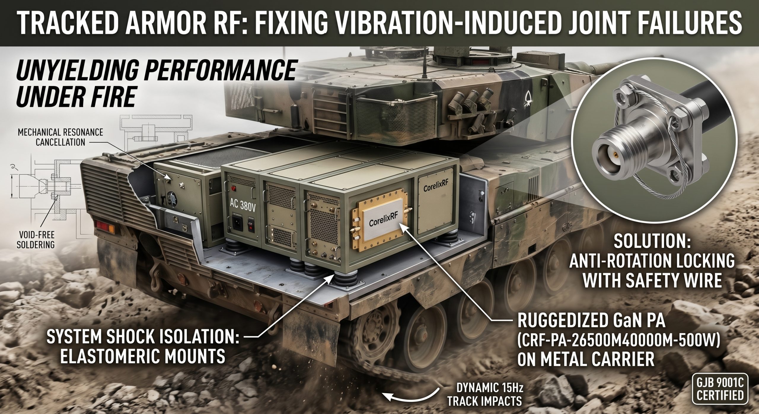
Tracked Armor RF: Fixing Vibration-Induced Joint Failures solves severe hardware degradation. Tracked armor operations subject communication systems directly against harsh physical forces. This article explains physical failure mechanisms inside military microwave circuits. We present practical matching logic solving severe connector loosening issues.
1. Why Do Tracked Armor RF Systems Fail Constantly?
● Combat Vehicle Mechanics
● Electronic Warfare Reliability
● Radar System Diagnostics
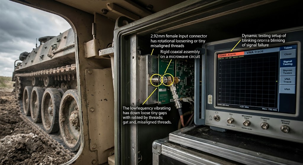
Continuous 15Hz track impacts shake military electronic warfare cabinets violently. Engineers stare at blank VNA screens during rigorous field testing. A sudden VSWR alarm triggers power reduction algorithms almost immediately. Combat units lose vital communication links mid-operation without any warning. Standard commercial RF components fail rapidly inside heavily armored chassis. Here’s the deal: Mechanical resonance tears apart rigid microwave traces. Tracked vehicles generate massive continuous mechanical stress across rough terrain. Commanders demand absolute reliability from their expensive signal jamming equipment. Three distinct field cases demonstrate these specific hardware failure patterns. First an anti-drone system experienced intermittent signal loss across frequencies. Turret rotation caused internal coaxial assemblies inside a chassis bend. Second a heavy tank radar showed degraded high-frequency receiver sensitivity. Technicians found fractured solder joints underneath critical GaN amplifier flanges. Third a mobile jammer suffered complete output power stage destruction. Intense engine vibrations loosened a primary 2.92mm female input connector. These distinct catastrophic failures require fundamentally different hardware selection logic. Source factory engineers must analyze actual physical stress distribution patterns. You cannot deploy delicate laboratory equipment onto rugged battlefield machinery. We replace fragile consumer electronics utilizing military grade ruggedized components. This specialized environment requires exceptional engineering discipline.
Track-Induced Vibration Failure Modes
| Failure Component | Physical Cause | System Consequence |
| 2.92mm Connector | Rotational loosening | VSWR alarm triggering |
| Solder Joint | Shear stress cracking | Intermittent signal loss |
| Rigid Coaxial | Bending fatigue | Complete power drop |
2. How Does Low-Frequency Vibration Destroy Solder Joints?
● Micro-cracking Mechanics
● Thermal Expansion Mismatch
● Material Fatigue Accumulation
Low-frequency vibrations transfer destructive kinetic energy into delicate circuit assemblies. Massive metal vehicle hulls amplify specific mechanical resonance frequency bands. What’s the real story? Micro-cracks propagate slowly across countless thermal cycles. Solder balls absorb severe shear stress during rapid armor movements. Differential thermal expansion rates compound this physical damage over time. Copper traces expand differently compared against rigid ceramic substrate materials. We observed microscopic fractures spreading beneath high-power transistor mounting flanges. Repeated track impacts force brittle intermetallic layers open microscopic fissures. These tiny invisible cracks increase local electrical resistance quite dramatically. Higher resistance generates extreme localized heating during continuous transmission operations. Heat accelerates crack propagation creating a vicious destructive feedback loop. A once solid electrical connection becomes a sparking intermittent nightmare. Engineers investigating broken modules frequently miss these microscopic physical fractures. Standard continuity tests might show normal results during static laboratory conditions. Dynamic testing using vibration tables reveals these hidden catastrophic flaws. Three specific evaluation metrics expose vulnerable circuit board assembly techniques. We monitor real-time phase stability during intense multi-axis shake testing. Technicians measure dynamic insertion loss variations across entire operating bands. Specialists analyze cross-sectional microscopic photography examining failed solder joint structures. Operating temperatures spanning 0 to 50 °C exacerbate these stresses constantly.
Solder Joint Degradation Stages
| Degradation Stage | Physical Symptom | Electrical Impact |
| Initial Phase | Microscopic surface fissures | Negligible change |
| Middle Phase | Crack propagation across pad | Slight impedance shift |
| Final Phase | Complete physical separation | Catastrophic signal failure |
3. What Are The Hidden Traps In Standard BOM Selection?
● Commercial Component Weaknesses
● Substrate Rigidity Issues
● Cost Reduction Consequences
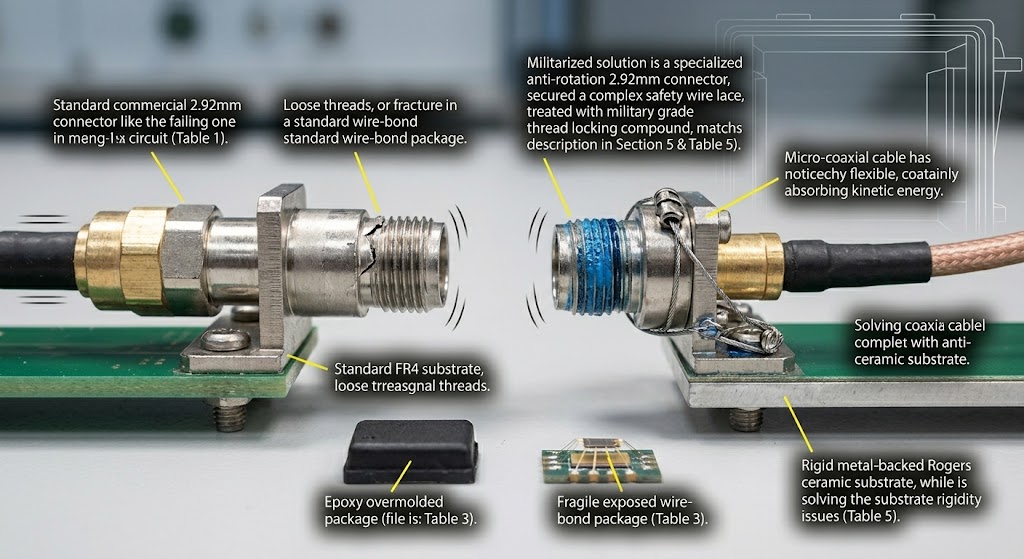
System integrators often select components utilizing standard commercial databanks blindly. Purchasing departments prioritize lower costs over extreme mechanical survival capabilities. This is where it gets interesting Ordinary FR4 circuit boards flex disastrously under constant heavy vibration. High-frequency Rogers materials lack sufficient mechanical rigidity without proper backing. Component datasheets rarely specify performance under continuous 20G shock conditions. Designers specify standard surface-mount capacitors ignoring mass-induced acceleration shearing forces. A heavy component simply rips its copper pads straight off. Commercial-grade power dividers split apart internally during rapid temperature cycling. Three distinct BOM selection errors cause predictable field deployment failures. First integrators choose cheap connectors lacking specialized anti-vibration locking mechanisms. Second buyers procure standard wire-bonded packages instead of robust overmolded designs. Third design teams ignore specialized conformal coating requirements completely. Uncoated boards allow moisture ingress exacerbating vibration-induced physical component rubbing. We analyze military failure reports identifying these specific component weaknesses. An electronic warfare jammer requires parts matching harsh operational realities. Every single capacitor must survive brutal mechanical shock wave forces. We reject components lacking comprehensive military standard environmental test data. Standard designs fail satisfying stringent GJB 9001C military quality requirements.
BOM Selection Pitfalls
| Component Type | Commercial Weakness | Military Requirement |
| Substrate | Flexible FR4 | Metal-backed Rogers |
| Connector | Standard thread | Anti-rotation lock |
| Package | Exposed wire bonds | Epoxy overmolded |
4. How Do We Design Frontend Matching Networks For Armor?
● Mechanical Decoupling Strategies
● Impedance Control Under Stress
● Ruggedized Circuit Topologies
RF front-end architecture demands careful mechanical decoupling inside tracked vehicles. Long rigid coaxial cables transmit destructive mechanical forces between modules. Ready for the good part? We implement flexible micro-coaxial assemblies reducing stress transmission significantly. Engineers distribute matching networks across physically isolated sub-assemblies very strategically. A centralized rigid matching block cracks under continuous torsional twisting. We utilize distributed element filters absorbing minor physical substrate deformations. Coplanar waveguide structures offer better mechanical stability compared against microstrip. Three specific architectural choices improve overall system mechanical shock resilience. We specify heavy metal carrier plates providing immense physical rigidity. Technicians bond ceramic substrates directly onto these thick metal carriers. Designers minimize unsupported trace lengths preventing damaging harmonic structural resonances. Active components require precise impedance matching despite shifting physical dimensions. Constant vibration causes minor capacitive changes between adjacent conducting surfaces. Our broadband matching topologies tolerate minor parasitic capacitance variations easily. We simulate mechanical deformation impacts calculating resultant electrical performance shifts. A ruggedized front-end maintains acceptable return loss despite physical warping. High-frequency bands expose every tiny manufacturing flaw during vehicle movement. Ka-band signals reflect aggressively when internal connector dimensions shift slightly. Our design philosophy prevents these catastrophic microscopic shifts from occurring.
Matching Network Resilience
| Design Strategy | Mechanical Benefit | Electrical Benefit |
| Flexible Coaxial | Absorbs vibration energy | Maintains phase stability |
| Metal Carriers | Prevents substrate bending | Keeps trace impedance |
| Distributed Filters | Tolerates minor warpage | Reduces return loss |
5. Why Do Standard Connectors Loosen Under Constant Shock?
● Thread Loosening Physics
● Torque Relaxation Phenomena
● Interface Degradation
Standard threaded RF interfaces fail predictably under continuous tracked movement. Rotational kinetic energy slowly unscrews perfectly torqued SMA mating nuts. You might be wondering: How much torque withstands track vibrations? The answer requires specialized locking mechanisms beyond simple torque wrenches. Constant low-frequency rumble causes microscopic slipping between mated thread surfaces. This slipping gradually reduces clamping force connecting center pin contacts. A loose connector introduces air gaps causing massive impedance mismatches. Reflected power surges backward triggering immediate system damage protection protocols. Three documented cases illustrate this specific mechanical loosening failure mode. A mobile radar system lost its primary antenna feed connection. A heavy armored vehicle navigated a rocky dry river bed. Severe chassis twisting forces sheared a locked WR28 waveguide flange. An internal 2.92mm female connector unscrewed itself dropping output power. We mandate specialized anti-rotation connector designs solving this exact problem. Engineers apply military-grade thread locking compounds preventing microscopic rotational slipping. Safety wire secures critical flange bolts stopping any backward movement. Every physical interface must remain locked during brutal continuous shaking. We test these interfaces using extreme shock simulation profiles repeatedly. The resulting connection withstands massive physical abuse without failing electrically.
Connector Anti-Loosening Methods
| Method | Application Area | Effectiveness Level |
| Thread Locker | SMA / 2.92mm nuts | Moderate |
| Safety Wire | Waveguide flanges | Very High |
| Anti-rotation | Blind mate connectors | High |
6. What Architecture Withstands Cabinet System Stresses?
● Heavy Weight Management
● Shock Mount Engineering
● Structural Resonance Control
A 300 kg cabinet system requires massive structural engineering efforts. Tracked armor movements toss heavy enclosures generating immense G-forces internally. Let that sink in for a moment. Our design incorporates specialized elastomeric shock mounts isolating internal electronics. These mounts absorb destructive 15Hz track impacts preventing chassis destruction. We calculate center-of-gravity locations balancing heavy power supply transformers carefully. Unbalanced loads snap mounting brackets during violent vehicle combat maneuvers. Three architectural principles guide our heavy equipment cabinet construction process. First we utilize welded tubular steel internal framing structures exclusively. Second engineers deploy multiple internal damping layers killing high-frequency ringing. Third heavy RF amplifier modules mount near rigid floor structures. A high center-of-gravity causes disastrous swaying motions ruining waveguide alignments. The CRF-PA-26500M40000M-500W model utilizes thick machined aluminum housing enclosures. This rigid housing prevents physical twisting protecting delicate internal microelectronics. We test these massive cabinets using giant hydraulic shaker tables. Instruments measure mechanical transfer functions ensuring internal resonance remains low. Power supplies utilizing AC 380V must remain perfectly secured structurally. Massive weight requires uncompromising mechanical foundation designs surviving armored transport.
Cabinet Structural Parameters
| Component | Material/Type | Purpose |
| Framework | Welded tubular steel | Maximum rigidity |
| Shock Mount | Elastomeric isolator | Vibration absorption |
| Enclosure | Machined aluminum | Twist prevention |
7. How Does Advanced Technology Solve Power Drops?
● High Frequency Performance
● GaN Material Advantages
● Output Stability Under Duress
Design based on advanced GaN technology provides extreme operational durability. Gallium Nitride devices handle higher operating temperatures compared against GaAs. But wait, there’s more. The CRF-PA-26500M40000M-500W delivers 500W across 26,500 – 40,000 MHz continuous. Maintaining this massive power level requires robust semiconductor die attachment. Solder voiding under GaN chips causes catastrophic localized thermal runaway. We employ advanced vacuum soldering techniques eliminating dangerous trapped air. A perfectly void-free attachment prevents hot spots during continuous jamming. Three performance metrics highlight this advanced semiconductor technology application success. The amplifier maintains a tight 8 dB gain flatness specification. Gain reaches a minimum 57 dB across the entire band. Harmonics remain suppressed below -10 dBc during full power output. These electrical characteristics depend entirely upon stable mechanical die foundations. A cracked die attachment degrades power output long before failing. Our rigorous environmental screening weeds out weak semiconductor mounting flaws. A reliable GaN frontend survives extreme battlefield conditions without degrading. Operators depend upon this constant power output during critical missions. Wideband amplifiers require flawless assembly practices guaranteeing long operational lifespans.
CRF-PA-26500M40000M-500W RF Specs
| Parameter | Value | Condition |
| Frequency | 26,500 – 40,000 MHz | 50 Ω system |
| Output Power | 500 W | Rated maximum |
| Spurious | -60 dBc | Typical operating |
8. How Do We Prevent VSWR Alarms During Combat Movement?
● Protection Circuit Implementation
● Dynamic Impedance Handling
● Autonomous System Recovery
Combat vehicles encounter varying antenna environments causing rapid impedance shifts. Driving near metal structures reflects massive RF energy backward quickly. Truth be told: Built-in protection covering over-voltage and VSWR prevents catastrophic amplifier destruction. The system monitors forward versus reflected power continuously without pausing. Fast-acting directional couplers detect dangerous standing wave ratios within microseconds. An analog control loop throttles input drive avoiding transistor burnout. We integrate RS485 / LAN control interfaces reporting telemetry instantly. Three specific protection mechanisms ensure electronic warfare systems survive combat. First over-drive protection clamps excessive input signals entering the amplifier. Second temperature sensors monitor thermal baseplates triggering cooling fan maximums. Third rapid shutdown circuits isolate GaN drains during severe mismatch. A tracked vehicle bouncing across trenches damages external antenna elements. A broken antenna creates an infinite VSWR short circuit condition. The amplifier must survive this sudden complete load reflection safely. Our fast protection logic saves expensive RF hardware from destruction. Input power hitting 0 dBm triggers immediate internal safety protocols. Engineers specify 2:1 input VSWR handling preventing false alarm shutdowns.
Built-in Protection Features
| Protection Type | Trigger Condition | System Action |
| VSWR | High reflected power | Power fold-back |
| Over-temperature | Exceeding 50 °C | Fan speed increase |
| Over-drive | Input > 0 dBm | Gain reduction |
9. What Are The Thermal Dissipation Rules For Sealed Armor?
● Air Cooling In Confined Spaces
● Heat Flux Density Management
● Ambient Temperature Constraints
Tracked vehicles offer terrible thermal environments cooking sensitive electronic equipment. A sealed armored hull traps heat raising internal ambient temperatures. Here is the kicker: An 8000W power consumption generates massive waste heat loads continuously. We implement aggressive forced air cooling keeping semiconductor junctions cold. Operating temperature must remain strictly between 0 and 50 °C. Designing thermal management inside cramped military spaces requires extreme precision. Three distinct thermal design rules govern our high-power amplifier construction. We utilize massive copper heat spreaders pulling heat from dies. High-CFM military grade fans force ambient air across finned heatsinks. Engineers route exhaust airflow away from sensitive intake venting paths. Recirculating hot exhaust air destroys cooling efficiency causing thermal shutdowns. The AC 380V supply drives powerful cooling blowers moving massive airflows. We simulate thermal fluid dynamics analyzing air currents inside cabinets. A well-designed cooling system prevents localized hot spots under vibration. Thick thermal interface materials crack unless compressed evenly using bolts. We torque heatsink mounting hardware verifying perfect flat surface mating. Cooling performance dictates overall system reliability inside hot desert battlefields.
Thermal Management Parameters
| Component | Characteristic | Specification |
| Power Supply | AC 380V±10% | Provides blower power |
| Cooling Method | Air cooling | Forced convection |
| Operating Temp | 0 to 50 °C | Strict ambient limit |
10. How To Evaluate System-Level Reliability For Electronic Warfare?
● Comprehensive Testing Regimens
● Interface Communication Checks
● Final Qualification Standards
Evaluating system-level reliability demands rigorous testing exceeding standard commercial procedures. We subject every unit against brutal mechanical and electrical profiles. Consider this: A single loose data cable disables an entire jamming system. We verify the RS485 / LAN control interface under vibration. Test data and pattern files support comprehensive project review evaluations. Three final qualification steps guarantee battlefield readiness for armored units. First technicians run continuous full-power transmission tests checking thermal stability. Second systems endure massive multi-axis shaker tables simulating rough terrain. Third we monitor spurious emissions ensuring absolute spectral purity compliance. Spurious signals must remain below -60 dBc preventing fratricide interference. Compliance frameworks include CE / FCC and ISO 9001 certifications. We adhere strictly following rigorous GJB 9001C military quality standards. These comprehensive evaluations prove our hardware survives actual combat deployments. Engineers can trust CorelixRF solutions delivering unyielding performance under fire. A fully qualified RF subsystem guarantees successful electronic warfare operations. We document every single test result providing complete customer transparency.
Qualification Framework
| Certification | Focus Area | Standard |
| Quality | Management | ISO 9001 |
| Military | Reliability | GJB 9001C |
| Emissions | Regulation | CE / FCC |
Conclusion
Tracked armor environments destroy ordinary RF front-end matching networks quickly. Our rigorous engineering logic eliminates microscopic solder cracking and loosening. A proper hardware selection requires deep understanding regarding physical stresses. Contact CorelixRF evaluating our ruggedized solutions solving your tough integration problems.
FAQ
Q1: What is the frequency range and output power? The frequency range covers 26,500 – 40,000 MHz delivering 500 W.
Q2: How does the built-in protection work? Built-in protection monitors over-voltage, over-temperature, over-drive, preventing VSWR damage.
Q3: What cooling method is used for this system? The system utilizes an aggressive air cooling method preventing overheating.
Q4: What control interfaces are available for system integration? Control interfaces include RS485 / LAN supporting seamless remote management.
Q5: What are the typical applications for this amplifier? Applications include test & measurement, communication, interference, and aviation control.
Translate rugged-site symptoms into a complete RF-chain review
Rugged RF issues often combine grounding, vibration, thermal range, connector retention, signal source stability and amplifier power margin. Share the site condition and acceptance evidence needed before choosing a platform.
Recommended next step: send the operating band, output power target, duty cycle, load condition, control interface, protection or thermal limits and required FAT documents. CorelixRF can review this How to Eliminate Vibration-Induced RF Joint Failures Using GaN PAs? requirement against standard RF amplifier platforms, RF front-end options and controlled customization paths.