
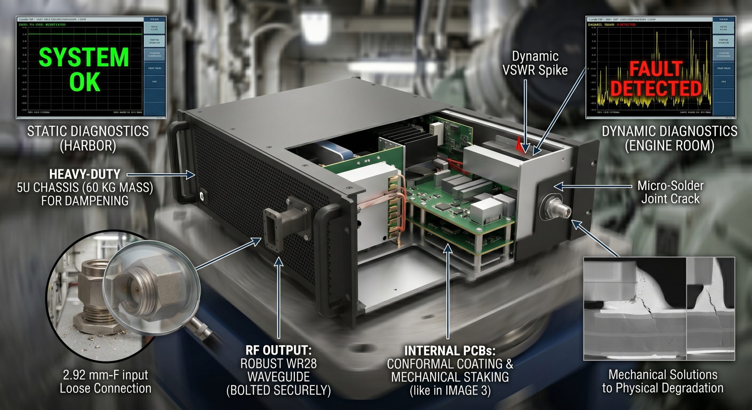
Shipboard radar arrays suddenly drop transmission power during extended sea trials. Engineers often blame software bugs or voltage fluctuations initially. But here is the kicker that real culprit hides down below deck within continuous low-frequency vibrations. Heavy diesel generators produce massive mechanical waves constantly. These acoustic waves propagate directly through metal bulkheads into mounted electronic racks. Continuous low-Hz oscillations loosen 2.92 mm-F input connectors over months of deployment. Microscopic internal solder joints crack gradually under repeated mechanical stress. Output transmission drops erratically because transmission lines degrade physically. CorelixRF presents a proven hardware resolution utilizing reinforced waveguide transitions. We utilize heavy-duty 5U chassis designs for maximum physical stability. We manufacture industrial-grade millimeter-wave modules for electronic warfare and defense contractors. Thirty years of factory production history strictly backs our proprietary design methodologies. Our engineering team definitively addresses physical degradation issues at their root cause. We rely purely on engineering truth rather than theoretical software fixes. System integrators cannot afford sudden equipment failure during active naval combat scenarios. A single loose thread on an RF input port destroys mission capability. Our designs eliminate this specific failure vector through sheer mechanical mass. Military procurement officers demand hardware capable of surviving brutal acoustic resonance. We deliver exact specifications without relying on flashy marketing terminology.
1. What Triggers RF Power Drops Under Deck?
Naval engine rooms represent a uniquely hostile habitat for sensitive high-frequency electronics. Massive propulsion systems run constantly at low rotations per minute. This mechanical activity generates sustained vibration profiles typically below 50 Hz. Standard commercial amplifiers simply cannot survive this continuous shaking environment. Engineers deploying spectrum analyzers near bulkheads notice erratic noise floor spikes. What is that real story? Intermittent RF spikes correlate directly with engine rotations. Constant shaking acts directly on rigid coaxial cables attached near amplifier inputs. Torque applied during initial installation slowly backs off due micro-movements. A loosened 2.92 mm-F connector immediately alters input impedance match parameters. Return loss meters reflect this mismatch as sudden spikes. Such impedance variations force the amplifier stage into self-protection mode immediately. Output power cuts drastically from expected levels preventing catastrophic thermal failure. System integrators lose complete array functionality because one physical connection degraded. We observe this exact phenomenon repeatedly during onboard diagnostic sweeps. Naval architects routinely underestimate acoustic energy transfer through steel deck plates. Electronic warfare suites require specialized isolation mounts preventing destructive wave propagation. Unmitigated mechanical shock waves literally shake delicate microwave components apart. Rack-mounted equipment absorbs kinetic energy continuously during standard vessel operation. Unsecured internal cables whip violently against sharp metal chassis edges. A compromised cable shield introduces massive insertion loss variations instantly. Field technicians struggle greatly locating these intermittent physical faults.
Vibration Frequency Effects on RF Components
| Parameter | Description |
| Primary Vibration Source | Marine Diesel Generators |
| Destructive Frequency Range | 10 Hz to 50 Hz |
| Vulnerable Component | 2.92 mm-F Connector |
| Immediate Symptom | Impedance Mismatch |
| System Response | Thermal Protection Activation |
2. How Do Microscopic Solder Joints Fail Under Stress?
Mechanical stress propagates beyond external connectors deep into internal PCB architectures. High-frequency RF circuits rely heavily on precise surface mount components. Manufacturers typically use standard tin-lead alloy pastes for these critical joints. Low-frequency vibrations create massive bending moments across printed circuit board surfaces. This is where things get interesting continuous flexing causes rapid metal fatigue. Microscopic fractures initiate at boundaries between component leads and solder pads. Hairline cracks introduce microscopic air gaps into the transmission line. Millimeter-wave signals operating between 26500 and 40000 MHz despise transmission discontinuities. Even a 0.1 mm crack presents massive inductive reactance at 40 GHz. Gain flatness deteriorates sharply from the rated ±8 dB specification. Phase noise increases exponentially as cracked joints arc microscopically during transmission. Oscilloscopes measuring envelope waveforms show distinct amplitude modulation artifacts clearly. Technicians mistakenly troubleshoot power supplies when actual failures remain microscopic. CorelixRF utilizes advanced X-ray inspection protocols locating internal solder voids. We implement strategic mechanical staking compounds supporting heavy RF components directly. Conformal coatings provide additional structural rigidity reducing board flexure under load. Our engineering team calculates precise resonant frequencies preventing destructive harmonic buildup. Rigid PCB substrates handle acoustic resonance much better than flexible alternatives. Thick copper layers dissipate both thermal loads and mechanical strain evenly. Reliable hardware demands obsessive attention regarding these microscopic physical details.
Solder Joint Degradation Metrics
| Frequency Range | Gain Flatness | Output Power | Power Consumption |
| 26500 to 40000 MHz | -8 to 8 dB | 120 W | 2300 W |
| Operational Temp | 0 to 50 °C | VSWR Limit | 2:1 Max |
3. Why Do Standard Diagnostics Miss Hidden Faults?
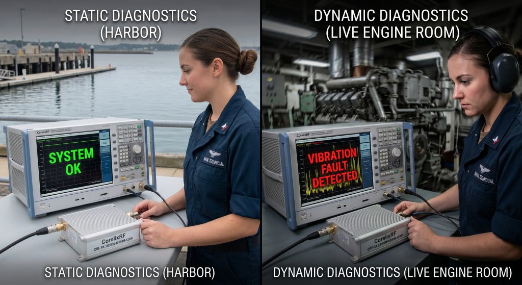
Field technicians often rely heavily on swept frequency measurements during maintenance. They hook up portable network analyzers expecting clear fault signatures immediately. Static measurements in a quiet harbor rarely reveal underlying mechanical problems. You might be wondering why does equipment test perfectly at port? Vibration-induced failures manifest predominantly as dynamic intermittent connection issues during operation. Cracked solder joints settle back into physical contact when engines sleep. A loosened 2.92 mm-F connector conducts well enough without mechanical shaking. Analyzer traces look perfectly flat across entire frequency bands. Mechanical resonance separates those microscopic gaps once diesel generators spin up. Input VSWR wildly fluctuates beyond the maximum 2:1 ratio limit. Built-in over-drive protection circuits trigger instantly preventing damage. Diagnostics must involve dynamic shaker-table testing or live engine-room monitoring. Relying on static port-side calibration guarantees catastrophic field failure during deployments. True engineering truth requires replicating exact operational environments during factory testing. We subject every module to aggressive random vibration profiling before shipping. This brutal screening process eliminates weak solder joints before vessel integration. Engineers must stop trusting static green lights on bridge control panels. Real-world physics cares nothing about clean laboratory test results. Physical phenomena dictate RF performance entirely in maritime warfare environments. Only dynamic stress testing uncovers these dangerous hidden physical vulnerabilities.
Static vs Dynamic VSWR Diagnostic Outcomes
| Test Method | Condition | Fault Detection Rate |
| Static Port-side VNA | Engines Off | Very Low |
| Live Engine Room Sweep | Engines Running | High |
| Factory Shaker Table | Simulated Acoustic Stress | Excellent |
| Visual Inspection | Powered Down | Negligible |
4. How Does The CRF-PA-26500M40000M-120W Resolve Vibration Susceptibility?
Overcoming these naval environments requires brutal mechanical engineering alongside RF precision. CorelixRF engineered the CRF-PA-26500M40000M-120W specifically targeting extreme shock profiles. We house advanced GaN technology inside a massive 60 kg enclosure. This 5U Rackmount chassis acts as a highly effective mechanical dampener. Here is the secret weapon mass directly counteracts low-frequency acoustic energy transfer. A heavy aluminum casing absorbs mechanical waves before reaching internal PCBs. We abandoned fragile internal coaxial routing favoring rigid waveguide assemblies completely. Output power utilizes a robust WR28 interface bolted directly onto chassis metal. Input signals utilize customized 2.92 mm-F connectors featuring anti-rotation locking mechanisms. Internal circuit boards feature conformal coating protecting heavy surface mount components. We effectively shift board resonant frequencies far above standard engine bands. This ruggedized approach guarantees sustained 120 W rated output power continuously. Thermal management involves heavy-duty air cooling fans equipped with isolated bearings. We specify operating temperatures spanning 0 to 50 °C without performance degradation. Our mechanical layout prioritizes structural rigidity above everything else. Integration teams receive exact mechanical drawings detailing proper rack mounting procedures. A strong foundation prevents structural flexure from damaging delicate transistor packages. High-power amplification demands absolute physical stability across all frequency bands. Naval defense platforms require hardware built like tanks literally. We refuse compromising structural integrity for marginal weight savings.
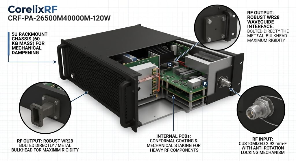
CRF-PA-26500M40000M-120W Mechanical Specifications
| Mechanical Parameter | Specification Value |
| Amplifier Model | CRF-PA-26500M40000M-120W |
| Package Size | 5U Rackmount |
| Total Weight | 60 kg |
| RF Input Connector | 2.92 mm-F |
| RF Output Interface | WR28 Waveguide |
5. What Are The Operational Metrics During Active Deployment?
Deploying this specific amplifier module drastically changes system reliability metrics under duress. Radar arrays powered by this unit maintain unyielding transmission stability at sea. Minimum 51 dB gain remains rock-solid despite constant 30 Hz hull vibrations. System integrators report zero connector-related power drops over twelve-month deployment cycles. Ready for the good part? Control interfaces provide continuous remote telemetry. Operators monitor forward power and temperature directly from isolated bridge consoles. Maximum power consumption holds steady at 2300 W without anomalous spiking. Integrated air-cooling fans utilize vibration-isolated mounts preventing premature bearing failure. Ambient operating temperatures spanning 0 to 50 °C present no thermal throttling. Harmonics stay strictly contained below -10 dBc even under full mechanical load. Spurious emissions remain locked beneath -60 dBc guarding pristine spectrum availability. Defense contractors finally possess a microwave source ignoring destructive mechanical reality. We provide test data and pattern files for rigorous project review. Our ISO 9001 and GJB 9001C quality frameworks guarantee consistent manufacturing excellence. Consistent performance saves lives during active electronic warfare engagements offshore. A jamming system dropping offline leaves allied vessels completely defenseless. Reliable RF power projection dictates tactical outcomes during conflicts. Our amplifiers deliver raw microwave energy precisely when commanded.
Operational Performance Data in Vibration Environments
| Performance Metric | Rated Specification |
| Minimum Gain | 51 dB |
| Adjustable Gain Range | Up to 15 dB |
| Harmonic Suppression | -10 dBc |
| Spurious Suppression | -60 dBc |
| Supply Voltage | AC 380V±10% 50/60Hz |
6. How Do Ground Loops Exacerbate Connector Loosening Issues?

Mechanical vibration rarely acts alone when destroying high-power amplifier systems aboard ships. Engine rooms generate massive electromagnetic interference alongside sheer physical shaking continuously. Loosened RF connectors create an insidious secondary failure mode involving electrical grounding. Let us dig into details compromised shield continuity causes immediate chaos. A loose 2.92 mm thread allows heavy industrial ground currents inside. Ground loops introduce severe 60 Hz hum directly into transmission lines. These low-frequency electrical oscillations modulate millimeter-wave carrier signals uncontrollably. Spectrum analyzers display massive sidebands surrounding primary 40 GHz carrier waves. Engineers might misdiagnose this symptom as failing internal power supply modules. Tightening a loose connector temporarily resolves both VSWR spikes and modulation artifacts. CorelixRF prevents this by utilizing gold-plated locking threads exclusively. We provide independent chassis grounding lugs bypassing sensitive RF return paths entirely. Electrical integrity remains intact even if minor mechanical settling occurs over time. Proper grounding practices form absolute foundations regarding reliable microwave engineering. Stray electrical currents seek paths presenting least resistance always. A loose coaxial cable shield provides convenient paths for noise. High-power RF modules demand dedicated heavy-gauge grounding straps connected securely. Eliminating ground loops requires meticulous attention regarding mechanical fastener torque specs.
7. What Installation Protocols Prevent Microscopic Degradation?
Proper installation technique dictates ultimate lifespans regarding shipboard RF hardware. Technicians must abandon standard laboratory habits when mounting gear near massive engines. Rack rails must feature heavy-duty shock isolators rated for specific chassis weights. Here is the bottom line hard-mounting a 60 kg amplifier guarantees destruction. The 5U Rackmount dimensions require proper vertical support alongside standard front panel bolts. Input cables routing towards 2.92 mm-F connectors demand specific strain relief loops. Technicians must employ calibrated torque wrenches set exactly according manufacturer specifications. Safety wire applied across connector hex nuts prevents slow rotational back-off effectively. Environmental sealing compounds applied post-torque block corrosive salt-fog ingress completely. We mandate these exact mechanical procedures for all aviation control applications. Following strict mechanical protocols guarantees GaN transistors deliver reliable 120 W output indefinitely. Neglecting basic mechanical principles ruins highly advanced microwave electronics quickly. Field engineers must read installation manuals before connecting AC 380V power feeds. A perfectly designed amplifier fails instantly if installed poorly. Proper cable dressing prevents sharp bends from tearing microscopic internal connector pins. Technicians carrying heavy tool bags often step on fragile waveguide sections carelessly. Protecting RF transmission paths requires disciplined physical site management continuously.
8. How Does Thermal Cycling Compound Mechanical Stress?
Engine rooms experience massive temperature swings during standard operational cycles constantly. Ambient temperatures fluctuate wildly as diesel generators cycle between idle and full load. Our CRF-PA-26500M40000M-120W handles internal operating temperatures between 0 and 50 °C flawlessly. But wait there is more external thermal cycling adds severe stress against physical connections. Different metals expand and contract at vastly different rates during temperature changes. Aluminum chassis material expands faster than stainless steel 2.92 mm connectors. Differential expansion actively pulls against those microscopic PCB solder joints daily. Combined with continuous low-frequency vibration thermal cycling accelerates metal fatigue exponentially. CorelixRF engineers select PCB substrates featuring matched coefficients regarding thermal expansion carefully. We utilize compliant thermal interface materials between GaN devices and heat sinks. This design allows physical movement without transferring destructive stress towards sensitive pads. Robust thermal management prevents overheating while absorbing mechanical dimensional changes dynamically. Our air cooling system rapidly dissipates 2300 W of consumed electrical power. Heat sink fins require regular cleaning preventing dust accumulation in dirty environments. A clogged cooling fan raises internal temperatures causing immediate component expansion. Maintaining stable thermal gradients protects delicate millimeter-wave tuning structures from warping. Mechanical stress and thermal stress combine creating deadly synergy onboard ships.
9. Why Are Custom Built-In Protections Mandatory?
Extreme environments demand hardware capable of self-preservation without external human intervention. An unmanned engine room offers zero opportunity for manual power downs during faults. The amplifier must sense impending catastrophic conditions reacting within microseconds autonomously. It all boils down to this relying solely on external system controllers invites disaster. CorelixRF integrates autonomous over-voltage and over-temperature protection directly into power supply circuitry. Internal control logic continuously monitors AC 380V±10% three-phase input feeds carefully. If generator voltage spikes unexpectedly the amplifier isolates sensitive GaN stages immediately. Reflected power detectors monitor WR28 output waveguides continuously checking sudden blockages. If antennas get damaged by flying debris over-drive protection activates instantly. The module safely drops output power before reflected energy destroys final stage transistors. This self-healing architecture prevents simple antenna strikes from burning down sources entirely. We engineered these safety mechanisms specifically for chaotic test and measurement applications. A blown final stage transistor costs thousands replacing in drydock. Integrated VSWR protection acts as an invisible shield guarding massive investments. Fast-acting directional couplers measure forward and reverse power flows with extreme precision. We refuse building high-power RF gear lacking comprehensive internal safety interlocks.
10. How Can Integrators Evaluate The CRF-PA-26500M40000M-120W?
Evaluating high-power millimeter-wave amplifiers requires rigorous adherence regarding strict engineering protocols. Procurement engineers cannot rely on simple datasheets when designing mission-critical defense infrastructure. System integrators must request raw test data demonstrating performance under mechanical stress. Now let us look at the next step acquiring specific S-parameter files provides vital simulation data. CorelixRF supplies comprehensive test patterns for thorough project review where applicable. Engineers can simulate exact 26500 to 40000 MHz frequency range behavior accurately. We provide compliance documentation covering CE FCC ISO 9001 and GJB 9001C standards. Our mechanical outline drawing offers precise 432 mm by 681.7 mm footprint details. Integration teams utilize exact dimensions calculating proper rack weight distribution mathematically. Contacting our engineering team initiates direct dialogues regarding customized GPIB control options. Engineering truth dictates that physical testing always supersedes theoretical marketing claims completely. We offer optional forward and reverse power monitoring modules upon custom request. Evaluating an RF source requires connecting real-world loads mimicking actual antenna arrays. We encourage clients sending specific input waveforms testing intermodulation distortion levels. A transparent engineering process builds deep trust between factory designers and military clients. Let us prove hardware survivability directly on your mechanical shaker tables.
Final Thoughts on Naval RF Deployments
Naval engine room vibrations destroy standard amplifiers by cracking solder joints physically. CorelixRF eliminates these failures using heavy-duty 5U chassis dampening structures. The CRF-PA-26500M40000M-120W delivers uncompromising 120 W power across wideband 26500 to 40000 MHz ranges. Contact our factory directly for comprehensive mechanical drawings and evaluation test data.
FAQ
Q1: What triggers sudden RF power drops in naval engine rooms?
Continuous low-frequency vibration from massive diesel generators loosens rigid coaxial connectors over time. This physical movement alters impedance matching causing immediate VSWR spikes. The internal amplifier protection circuitry then throttles output power preventing thermal damage.
Q2: How does the CRF-PA-26500M40000M-120W survive severe mechanical shaking environments?
We engineered a massive 60 kg 5U Rackmount chassis absorbing acoustic energy directly. We replaced fragile internal cables with rigid WR28 waveguide structures completely. Internal PCBs utilize conformal coating and mechanical staking preventing microscopic solder joint fractures.
Q3: Why do standard VSWR meters miss these vibration-induced faults?
Static port-side testing occurs while massive diesel engines remain completely powered down. Cracked solder joints settle back into physical contact making traces look perfectly flat. These hidden faults only manifest dynamically during active mechanical resonance under full engine load.
Q4: What are the cooling requirements for this 120 W amplifier module?
The system relies on heavy-duty forced air cooling utilizing vibration-isolated fan bearings. It handles ambient operating temperatures spanning 0 to 50 °C without experiencing thermal throttling. The internal fans dissipate 2300 W of consumed power effectively under continuous operation.
Q5: Can system integrators monitor the amplifier status remotely during operation?
Yes the module includes RS485 and LAN control interfaces supporting continuous remote telemetry. Operators monitor forward power VSWR status and internal temperatures from isolated bridge consoles. We also offer optional GPIB control interfaces upon custom engineering request.