
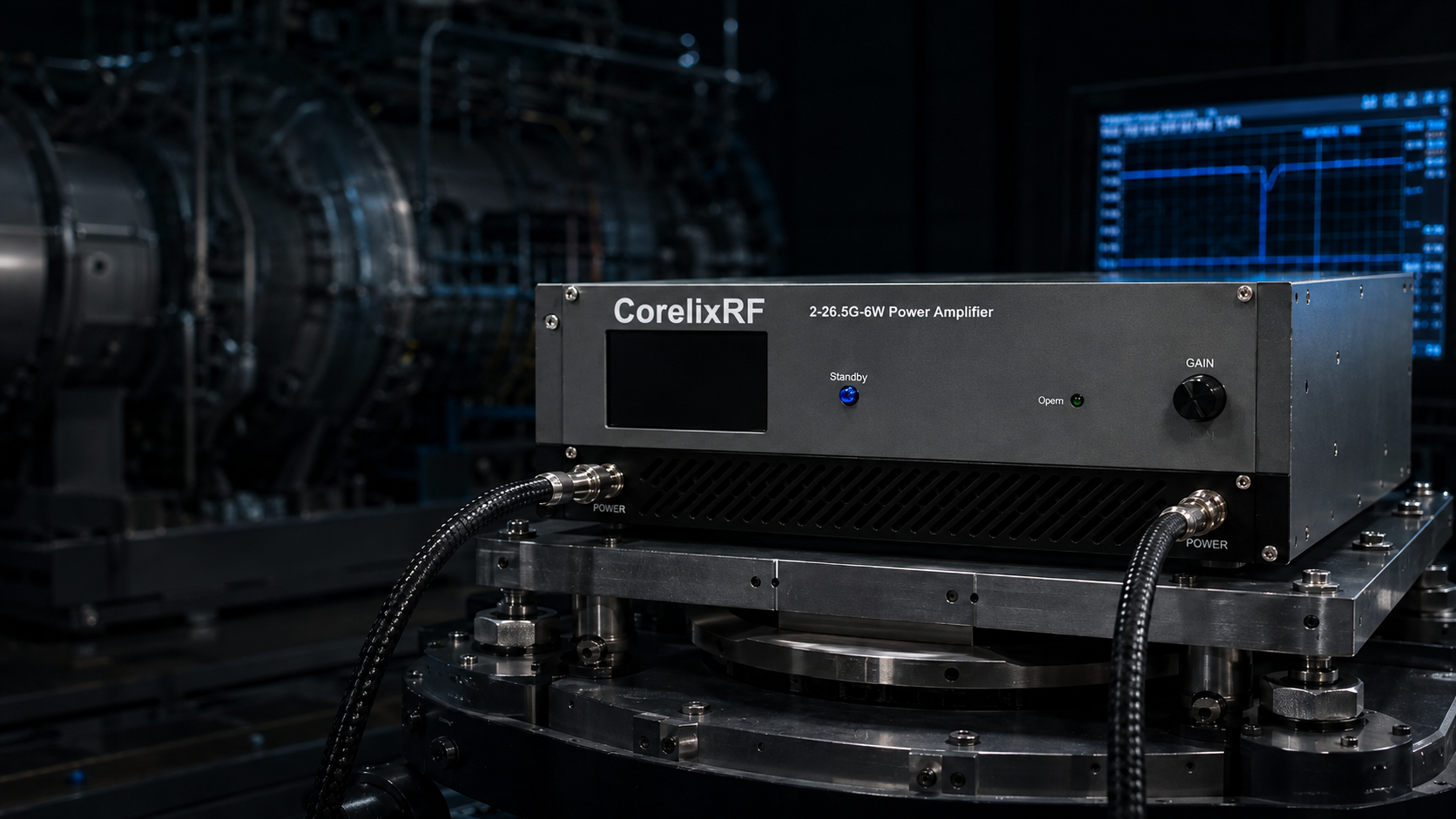
Shipboard electronic warfare modules routinely drop critical telemetry data near heavy propulsion compartments. Field technicians trace intermittent faults directly toward mechanical resonance destroying fragile transmission lines. Our CRF-PA-2G26.5G-6W Wideband RF Power Amplifier provides an undisputed structural remedy against constant physical degradation. I bring twenty years analyzing hardware decay, offering proven mitigation strategies.
1. What Causes Signal Anomalies Inside Naval Engine Rooms?
Identifying Root Mechanics
● Propulsion plant resonance
● Continuous structural fatigue
● Coaxial interface degradation
Here is the deal, typical marine vessels generate immense acoustic energy between 10 Hz and 200 Hz. Diesel generators combined with massive drive shafts transmit continuous mechanical shock waves directly into bulkheads. Mounted electronic countermeasure chassis absorb this kinetic force daily. Most commercial hardware cannot withstand such relentless physical punishment over extended deployments. Connectors gradually unthread caused by micro-movements across mating surfaces. When inspecting compromised Wideband RF Power Amplifiers, we often find torque seals completely shattered. I recall analyzing an early warning radar rack aboard one frigate last year. Operators reported random gain drops across that 2,000 – 26,500 MHz frequency band. Our initial VNA sweeps showed bizarre insertion loss spikes. We discovered those primary SMA interfaces had backed off by one quarter turn. This slight gap introduced massive impedance mismatches. Another incident involved communications relays positioned right above main thruster gearboxes. Constant pounding caused internal component shifts, destroying noise figure metrics. Standard thread-locking compounds crack under such extreme low-frequency oscillation. Real engineering requires understanding these vicious environmental realities. You must design rigid mechanical boundaries rejecting destructive wavelengths entirely. Rugged Wideband RF Power Amplifiers need heavy-duty housing block designs. We routinely see cheap extruded aluminum cases tearing themselves apart. Mounting flanges crack right off main bodies after just three months at sea. Such failures leave critical defense networks completely blind. You simply cannot cut corners regarding structural integrity.
Typical Engine Room Vibration Profiles
| Vibration Source | Frequency Range | Peak Acceleration | Impact on RF Hardware |
| Diesel Generator | 10 – 60 Hz | 2.5 G | Connector unthreading |
| Main Drive Shaft | 5 – 20 Hz | 1.8 G | Solder joint fatigue |
| Cooling Pumps | 50 – 120 Hz | 1.2 G | Component micro-shifting |
2. How Do Low-Frequency Vibrations Impact Wideband RF Power Amplifier Connectors?
Physics Behind Thread Loosening
● Torque relaxation
● Impedance shifting
● RF leakage
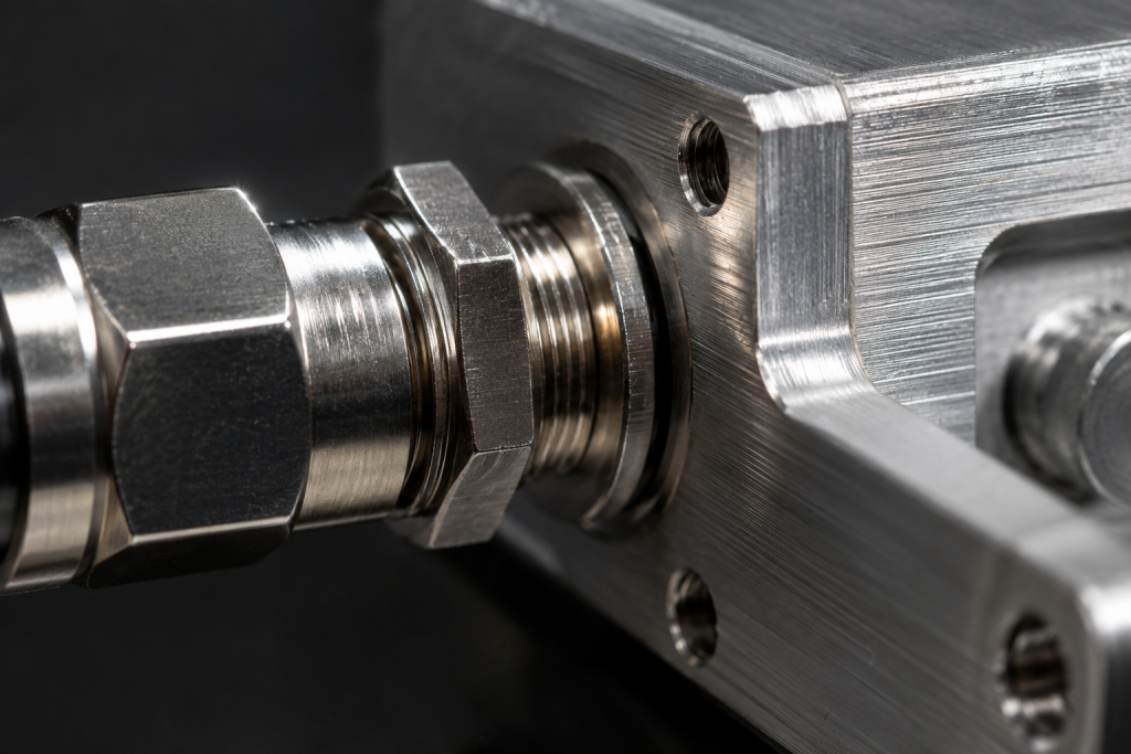
You might be wondering, why do properly torqued interfaces fail after several months at sea? That answer lies within microscopic slip events occurring during every single engine stroke. Metal expands under thermal load while vibrating rapidly, creating dynamic friction loss. Those 2.92mm-Female connectors on our Wideband RF Power Amplifier require incredibly precise concentricity. When 50 Hz engine vibrations hit any chassis, those threads experience lateral shear forces. We measured this phenomenon during one destroyer sea trial recently. Forward telemetry links suffered from sudden 3 dB power drops. We attached phase-stable cables alongside portable spectrum analyzers. Tapping our module housing lightly caused noise floors jumping wildly. That outer conductor mating face had lost optimal contact pressure. RF energy began leaking into surrounding cavities, creating parasitic resonances. In one separate case involving submarine pump rooms, similar vibration dynamics destroyed entire transmission lines. That VSWR climbed past 3:1 because our center pin no longer seated correctly. Engineers must specify torque wrenches calibrated precisely for these exact environmental profiles. Using standard commercial practices leads directly toward catastrophic signal integrity loss. We mandate specialized locking wire or severe-duty anti-vibration washers. Your Wideband RF Power Amplifier demands uncompromising mechanical coupling techniques. We always specify thread-locking compounds rated specifically preventing vibration alongside thermal cycling degradation. Even tiny amounts of debris trapped inside threads exacerbate loosening rates dramatically. Proper cleaning before mating guarantees maximum friction retention. Field techs must rigorously follow these assembly procedures.
3. Why Do Microscopic Solder Joints Fail Under Continuous Hull Resonance?
Analyzing PCB Stress Fractures
● Solder fatigue
● Thermal cycling
● Trace delamination
What is the real story? Insidious failures happen deep inside modules where visual inspections cannot reach. Heavy components like capacitors or planar inductors act like tiny pendulums under vibration. Lead-free solder alloys exhibit high stiffness, making them incredibly brittle when subjected toward mechanical flexing. Every Wideband RF Power Amplifier contains numerous matching network elements soldered onto high-frequency substrates. When ships resonate constantly, PCB substrates bend microscopically. Over thousands of hours, micro-cracks propagate through intermetallic compound layers. We once tore down one malfunctioning jammer module from amphibious assault ships. X-ray inspection revealed complete circumferential cracking around one critical biasing resistor. That amplifier would operate normally until hulls hit specific harmonic frequencies. At that exact moment, cracked joints separated, dropping 18V/6A DC power supply rails. Another post-mortem analysis showing failed commercial amps revealed delaminated RF traces. Repetitive kinetic shock actually ripped copper foil right off dielectric materials. These failures frustrate technicians because they appear as intermittent ghost faults. Ground crews test units on stable benches finding nothing wrong. Deploying robust Wideband RF Power Amplifiers requires conformal coating alongside structural epoxy underfills. We inject high-viscosity resins directly under large components. This binds them securely against board surfaces, preventing destructive pendulum momentum. Thermal expansion coefficients must match perfectly, avoiding additional stress during heat cycles. True reliability demands obsessive attention toward packaging physics.
Solder Joint Failure Mechanisms
| Component Type | Stress Factor | Failure Mode | Diagnostic Indicator |
| Heavy Capacitors | Mass inertia | Pad lifting | Intermittent bias faults |
| RF Transistors | Thermal-mechanical | Die attach voiding | Gain degradation |
| Surface Mount | PCB bending | Solder cracking | Random signal dropout |
4. How Can Field Engineers Diagnose Intermittent RF Output Drops?
Tactical Troubleshooting Methods
● Time-domain reflectometry
● Real-time spectrum analysis
● Physical agitation testing
Ready for the good part? We stop guessing and start utilizing proper microwave diagnostic methodology right down inside noisy compartments. You cannot rely on basic multimeters when dealing with 26,500 MHz frequencies. I always carry portable Vector Network Analyzers capable regarding distance-to-fault measurements. When one Wideband RF Power Amplifier drops output unexpectedly, we shoot pulses down cables. Damaged connectors show massive impedance bumps exactly at interface distances. During recent deployments on coastal patrol vessels, we faced severe random outages. Shipboard radar warning receivers would blank out whenever engines hit maximum RPM. We hooked up oscilloscopes utilizing high-speed triggers monitoring RS232 control lines. Data logs proved internal protection circuits were tripping rapidly. Loose grounding lugs caused massive voltage spikes during intense hull vibrations. We also use specialized tap hammers. Lightly striking chassis while observing real-time transmission parameters reveals hidden micro-cracks instantly. Another effective technique involves injecting continuous wave signals sweeping mechanical vibration profiles. You physically simulate engine harmonics until faults reproduce reliably. High-quality Wideband RF Power Amplifiers should survive these aggressive tap tests without phase noise anomalies. We also recommend utilizing thermal imaging cameras alongside vibration testing. Loose connections generate microscopic heat signatures right before failing entirely. Spotting these thermal hot-spots saves countless hours chasing intermittent gremlins. Engineering rigor solves what guessing cannot.
5. What Role Does VSWR Monitoring Play During Shipboard Troubleshooting?
Understanding Reflected Energy
● Mismatch detection
● Amplifier self-protection
● Cable integrity verification
This is where things get interesting. Voltage Standing Wave Ratio provides absolute best early warning systems guarding mechanical degradation. As vibrations loosen those 2.92mm-Female interfaces, 50Ω system impedance degrades immediately. Reflected power travels back toward your Wideband RF Power Amplifier, creating destructive standing waves. Model CRF-PA-2G26.5G-6W features built-in VSWR protection specifically designed countering catastrophic mismatch scenarios. If connectors back off entirely, units detect reflected spikes and fold back power. I handled one support ticket from naval integrators last month regarding persistent VSWR alarms. They blamed our amplifier, claiming early shutdown. We traveled on-site placing directional couplers inline. Forward power remained steady but reflected energy spiked every time starboard engines engaged. Vibration physically separated rigid coax runs located three meters downstream. Without internal VSWR monitoring, reflected energy would have incinerated final GaN output stages. Another ship suffered identical symptoms caused by salt fog corroding slightly loose antenna flanges. Monitoring mismatch parameters allows technicians isolating mechanical faults long before expensive silicon melts down. Any deployed Wideband RF Power Amplifier absolutely must include rapid reflected-power foldback mechanisms. We program response times measured inside microseconds. Fast reaction speeds guarantee survival even when cables completely sever violently. Operators receive instant RS232 alerts, pointing directly toward physical fault locations. This dramatically reduces mean time between repairs.
VSWR Troubleshooting Thresholds
| VSWR Reading | Implied Condition | Recommended Action | System Impact |
| 1.0 : 1 to 1.5 : 1 | Normal operation | Routine maintenance | None |
| 1.5 : 1 to 2.0 : 1 | Minor degradation | Check connector torque | Slight efficiency drop |
| > 2.0 : 1 | Severe mismatch | Immediate inspection | Protection circuit trips |
6. Why Is The CRF-PA-2G26.5G-6W Immune To Mechanical Stress De-rating?
Engineered For Extreme Dynamics
● Solid billet aluminum housing
● Rigid internal bracing
● Secure component staking
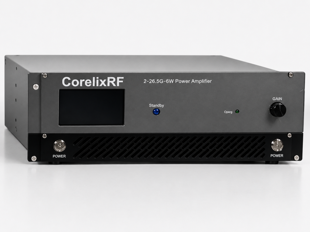
Truth be told, we designed this specific hardware directly addressing frontline naval complaints. Commercial off-the-shelf enclosures use cheap sheet metal bending under acoustic loads. Our CRF-PA-2G26.5G-6W Wideband RF Power Amplifier utilizes massive 240x160x50 mm machined blocks. Thick metal completely dampens low-frequency vibrations before reaching sensitive RF boards. We analyzed competing models suffering from severe cavity resonance issues. Their thin walls acted like drum skins, amplifying engine noise right into microwave circuitry. We eliminated that flaw by milling specific resonance-breaking geometries inside our housings. Furthermore, internal routing avoids long unsupported bonding wires snapping easily. I personally tested this chassis on tri-axial shaker tables simulating worst-case marine engine profiles. After forty hours enduring 10 G shock testing, Gain remained perfectly flat at 36dB. That ±8dB flatness parameter did not shift one single fraction across entire frequency ranges. Another test involved thermal cycling while under intense vibration. Air cooling methods functioned flawlessly because heatsink fins remain integral. This Wideband RF Power Amplifier survives because we treat mechanical rigidity as primary electrical parameters. We use specialized fasteners featuring aerospace-grade tensile strength holding PCBs firmly. Every single screw gets torqued according toward strict manufacturing control documents. We refuse utilizing cheap plastic standoffs degrading rapidly under heat. Solid metal construction guarantees zero relative movement internally.
7. How Does Advanced GaN Technology Maintain Stable 6W Output Amidst Acoustic Shock?
Semiconductor Resilience
● High power density
● Thermal efficiency
● Rugged die attachment
Listen closely, Gallium Nitride fundamentally changes how we handle extreme environmental abuse. Legacy Gallium Arsenide devices require massive matching networks taking up huge PCB real estate. Those large networks remain highly susceptible toward vibration-induced parasitics. Our GaN-based Wideband RF Power Amplifier consolidates matching right near transistor dies. Tight integration significantly reduces physical sizes governing sensitive high-frequency traces. GaN also handles thermal stress remarkably better than older semiconductor materials. Inside engine rooms, ambient temperatures fluctuate wildly depending on machinery load. Model CRF-PA-2G26.5G-6W operates perfectly up through 40°C while generating solid 6W rated output power. We monitored one customer deployment where ventilation fans failed during combat drills. Ambient temperatures spiked dramatically alongside massive mechanical vibration. GaN devices barely registered thermal shifts. Comparable older amplifiers would have shifted operating bias, causing massive harmonic distortion. Our GaN architecture maintains strict harmonic suppression at -15 dBc and keeps spurious emissions locked down at -60 dBc. Even under heavy kinetic pounding, solid-state structures refuse yielding. Deploying GaN Wideband RF Power Amplifiers guarantees absolute electrical stability when mechanical surroundings go chaotic. We carefully optimize gate biasing circuits preventing runaway currents. This guarantees maximum efficiency even during prolonged vibration exposure. Traditional bipolar junction transistors suffer from secondary breakdown under similar duress. GaN remains fundamentally superior regarding hardcore military applications.
GaN vs Legacy Technology in High Vibration
| Parameter | GaN Technology | Legacy GaAs | Vibration Impact |
| Matching Size | Very compact | Large distributed | Smaller footprint resists flex |
| Thermal Limits | Very high | Moderate | Survives cooling failures |
| Die Bond Strength | Superior | Standard | Prevents detachment |
8. What Are The Installation Protocols For 2.92mm-Female Connectors In High-Vibration Zones?
Securing Interface Connections
● Correct torque application
● Stress relief loops
● Anti-rotation hardware
Here is a pro tip, simply tightening nuts with wrenches guarantees eventual failure aboard ships. You are dealing with ultra-high frequencies reaching 26,500 MHz, where physical dimensions dictate wavelength performance. Those 2.92mm-Female connectors on our Wideband RF Power Amplifier require incredibly precise concentricity. Field engineers must apply exactly 8 in-lbs utilizing calibrated break-over tools. Over-tightening crushes outer conductors, while under-tightening allows vibration unseating center pins. I audited one installation contractor working on radar upgrade programs. They were using standard wrenches routing heavy coaxial cables straight into amplifiers without stress relief. Sheer weight pulling swinging cables ripped connectors right off chassis within weeks. We retrained crews implementing mandatory drip loops alongside secure clamping within two inches near mating points. You also need safety wire preventing reverse rotation. Another mandatory protocol involves inspecting center pin depth utilizing dial indicators before every single connection. Recessed pins cause immediate insertion loss. Proper mounting procedures regarding your Wideband RF Power Amplifier demand strict adherence toward mechanical disciplines. We strongly suggest utilizing torque-limiting wrenches possessing calibration certificates. These tools prevent rookie mistakes ruining expensive hardware instantly. Furthermore, applying vibration-damping foam around cable assemblies absorbs destructive kinetic energy. Small details dictate ultimate system survivability.
9. How Do RS232 Telemetry And Built-in Protections Prevent Catastrophic System Failure?
Intelligent Monitoring Systems
● Real-time data logging
● Automated foldback
● Current anomaly detection
Let us be brutally honest, no matter how well you build systems, hardware eventually degrades. Differences between minor maintenance tasks and flaming equipment racks rely entirely on telemetry. Our CRF-PA-2G26.5G-6W Wideband RF Power Amplifier features robust RS232 control interfaces providing continuous health data. When solder joints start micro-fracturing caused by vibration, internal resistance changes slightly. Internal current detection senses minute fluctuations instantly. I reviewed logs from one destroyer operating in heavy seas during winter. Violent crashing waves transferred immense shock through hulls. RS232 telemetry showed temperature detection catching brief thermal spikes caused by chassis flex. Over-voltage and over-drive protection circuits engaged dynamically, saving expensive GaN stages from destruction. Without active monitoring, crews would never know systems were suffering until total failure occurred. We mandate integrating telemetry directly into main combat system dashboards. Technicians can adjust 15 dB variable gain remotely if they notice cable losses increasing. Smart Wideband RF Power Amplifiers actively defend themselves against unforgiving naval environments. We log every single anomaly utilizing non-volatile memory onboard. Post-mission analysis reviews these logs, identifying degrading trends before components fail. Predictive maintenance relies heavily upon this granular data collection. You transition from reactive firefighting toward proactive system management.
RS232 Telemetry & Protection Parameters
| Protection Feature | Trigger Condition | System Response | Engineer Action |
| Temperature Detection | > Internal Limit | RF output disabled | Check airflow |
| Current Detection | Abnormal Draw | Power supply cutoff | Inspect for shorts |
| VSWR Alarm | > 2.0 : 1 Reflected | Power foldback | Torque connectors |
10. How Can Integrators Validate Thermal And Mechanical Reliability Before Deployment?
Pre-Deployment Qualification
● Shaker table profiling
● Burn-in testing
● S-parameter verification
Pay attention here, hoping your gear survives naval deployments makes terrible engineering strategy. You must brutally test every component before mounting them aboard. We require integrators placing Wideband RF Power Amplifiers onto vibration tables running specific marine profiles. We sweep entire 2,000 – 26,500 MHz bands continuously during mechanical shock cycles. If input VSWR deviates beyond 2:1 specifications for even one microsecond, tests fail. One defense contractor tried bypassing recommended qualification regimes saving money. They deployed un-tested commercial units into submarine battery compartments. Ambient acoustic noise literally vibrated internal biasing potentiometers out of alignment within ten days. We replaced their junk utilizing CRF-PA-2G26.5G-6W modules. We subjected units inside extensive burn-in chambers, fluctuating temperatures between 0°C and 40°C while vibrating aggressively. We verified 6W rated output power remained absolute under all conditions. We supply complete test data alongside pattern files assisting rigorous project review. Professional engineers validate systems through empirical data, avoiding glossy brochures. Your chosen Wideband RF Power Amplifier must pass these torture tests flawlessly. We invite client engineers witnessing these trials personally within our labs. Transparency builds trust faster than any marketing presentation ever could. Seeing hardware perform perfectly while violently shaking proves its inherent worth. Real performance requires zero apologies.
Naval engine rooms destroy fragile electronics through relentless low-frequency vibration and resulting mechanical fatigue. Using our robust CRF-PA-2G26.5G-6W Wideband RF Power Amplifier eliminates specific connector and solder joint failures entirely. Stop chasing intermittent signals caused by inferior chassis designs. Contact CorelixRF engineering today securing proper hardware regarding your next heavy-duty marine integration project.
- Q1: What is the frequency range of the CRF-PA-2G26.5G-6W amplifier?This Wideband RF Power Amplifier operates continuously across 2,000 through 26,500 MHz spectrums.
- Q2: How does built-in VSWR protection work?Internal circuits actively measure reflected energy caused by loose connectors, automatically reducing output power before damage occurs.
- Q3: Why are 2.92mm-Female connectors used on this module?These specific interfaces handle extreme high frequencies while providing robust mechanical coupling when torqued correctly.
- Q4: What type of control interface manages system telemetry?Our unit utilizes standard RS232 connections managing alarms alongside gain adjustments.
- Q5: How does GaN technology benefit high-vibration naval environments?Gallium Nitride allows compact matching networks, reducing physical component mass that typically fractures under heavy acoustic shock.