
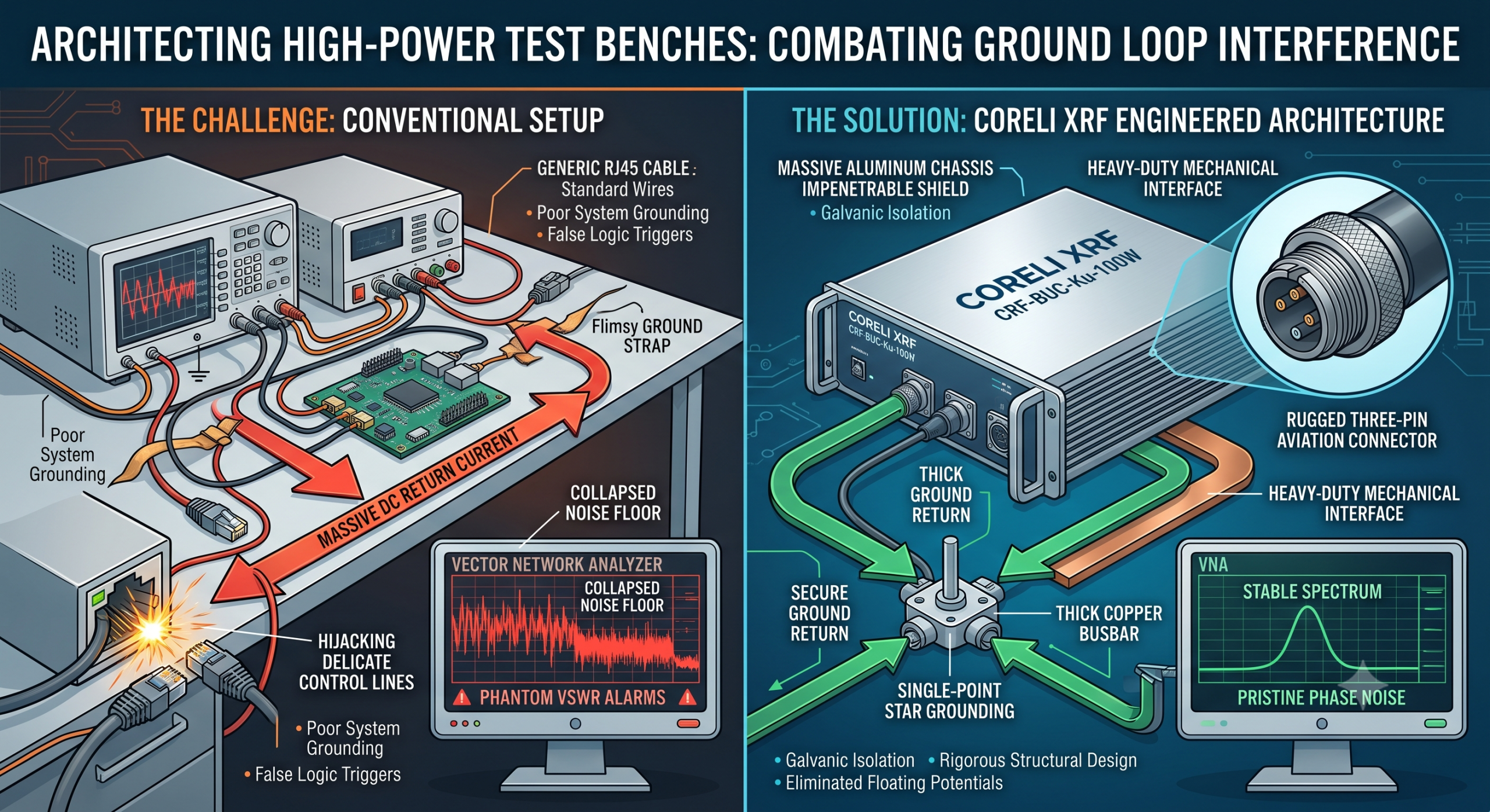
What creates true despair inside a microwave laboratory? You connect a Ku-band block upconverter operating at 14.5 GHz, initiate a 100 W CW sweep, and watch your vector network analyzer noise floor completely collapse. Here’s the deal: this catastrophic failure rarely originates from faulty RF components. Engineers consistently misdiagnose these phantom VSWR alarms and logic-level anomalies. We face a systemic grounding architecture flaw where massive DC return currents hijack delicate control lines.
1. What Exactly Causes Test Bench Ground Loop Interferences?
Anatomy of a Grounding Failure
What’s the real story? When evaluating high-power RF systems, power consumption typically reaches 450 W. That translates into nearly ten amperes flowing through a 48 V supply line. In an ideal laboratory environment, return current flows peacefully back through thick copper busbars. Real-world testing setups rarely possess perfectly equipotential surfaces. A voltage potential difference emerges between your DC power supply ground and instrument chassis ground. Your Ethernet monitoring cable suddenly becomes a path of least resistance. Millivolts of ground shift can easily violate CMOS logic thresholds on RJ45 pins. This specific condition triggers spurious hardware interrupts inside microcontrollers. The system processor incorrectly registers a catastrophic thermal event or a severe overcurrent situation. Your expensive VNA might display sudden gain drops because internal bias controllers shut down active amplification stages prematurely. Such misbehavior forces engineers into exhausting debugging cycles targeting nonexistent thermal issues.
| Parameter | Typical Bench Issue | Consequence |
| Ground Potential Shift | > 500 mV on logic ground | False logic state triggers |
| Return Current Path | Ethernet shielding | MCU interrupt storms |
| Power Supply Ripple | 60 Hz coupling | Phase noise degradation |
2. How Does High-Current Return Impact RF Performance?
The Silent Killer of Phase Noise
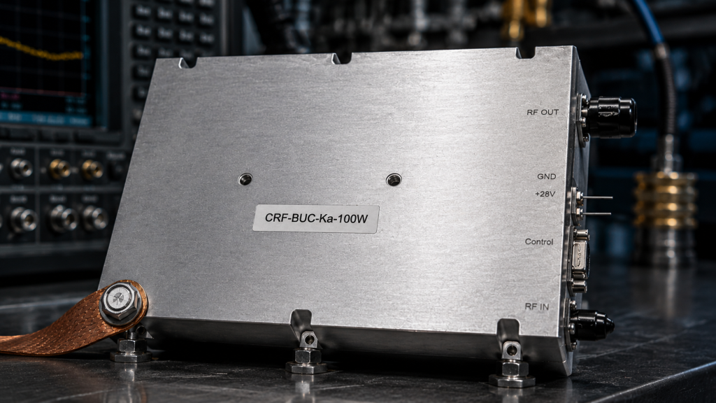
This is where it gets interesting… Ground loops do not just crash digital microcontrollers; they actively destroy critical microwave specifications. Modulating your internal power rails with stray AC currents degrades spectral purity severely. You expect your output phase noise tightly constrained at ≤-85 dBc/Hz @ 10KHz. Poor return paths inject low-frequency noise directly into voltage-controlled oscillators. A 10 MHz reference signal passing through an unbalanced coaxial connection will pick up this stray current loop. This unwanted modulation appears as aggressive sidebands around your 14.5 GHz carrier. We frequently observe spectrum analyzer traces showing elevated noise floors mimicking broadband amplifier instability. In reality, your RF frontend matching network remains perfectly fine. The actual culprit hides within substandard bench wiring routing 450 W of dissipation incorrectly. Addressing these physical phenomena requires understanding how magnetic fields couple into unshielded control wiring harnesses during transient power surges.
| Phase Noise Offset | Target Specification | Degraded Loop Performance | | | | | | 100 Hz | ≤-65 dBc/Hz | -40 dBc/Hz (Erratic) | | 1 KHz | ≤-75 dBc/Hz | -55 dBc/Hz (Elevated) | | 10 KHz | ≤-85 dBc/Hz | -70 dBc/Hz (Sidebands) | | 100 KHz | ≤-95 dBc/Hz | -85 dBc/Hz (Noise Floor) |
3. What Are Common BOM Selection Traps in Test Systems?
Avoiding Cheap Connector Pitfalls
But here’s the kicker… System integrators often ruin excellent RF chains by selecting inappropriate low-frequency connectors. Engineers might deploy standard plastic RJ45 jacks for monitoring, assuming ethernet traffic remains immune against nearby gigahertz radiation. A robust architecture demands strict galvanic isolation alongside heavy-duty mechanical interfaces. The CorelixRF methodology specifies a dedicated three-pin aviation connector handling primary 48 V supply feeds. This ruggedized military-grade component ensures contact resistance remains negligible even under maximum thermal stress. Cheap commercial connectors degrade over repeated mating cycles inside busy testing facilities. Their contact impedance rises, forcing return currents toward alternative paths like delicate communication interfaces. You must evaluate your Bill of Materials from an electromagnetic compatibility perspective. Every single metallic junction acts as a potential failure node when pushing 50 dBm of saturated output power. Selecting components based purely upon unit cost guarantees catastrophic measurement inaccuracies during critical validation phases.
| Component Type | Standard Lab Selection | Recommended High-Power Selection | | | | | | DC Power Input | Banana plugs | Three-pin aviation connector | | Comm Interface | Plastic RJ45 | Shielded aviation connector (RJ45) | | RF Output | SMA / 3.5mm | WR75 Waveguide |
4. How Does CorelixRF Solve the Isolation Challenge?
Physical Architecture for Superior Reliability
Ready for the good part? Resolving these brutal testing environment challenges requires more than applying ferrite beads arbitrarily. The CRF-BUC-Ku-100W model demonstrates proper systems-level defensive engineering. Our hardware isolates the primary power ground from digital logic references internally. When deploying this 5.5 kg aluminum block upconverter, its massive chassis provides an impenetrable shield against radiated emissions. We integrate a built-in high-power isolator protecting the output stage against severe mismatch conditions. If your WR75 waveguide connection loosens during violent vibrational testing, reverse RF currents safely dissipate into internal dummy loads. This architectural choice prevents reflected energy from coupling back into sensitive biasing circuits. The IP65 rating ensures environmental seals maintain continuous conductivity across all mating surfaces. Such rigorous structural design eliminates those dreaded floating ground potentials causing random Ethernet link drops. We fundamentally block errant DC return paths through physical separation and careful PCB layout geometries.
| Model Specification | CorelixRF Value | Engineering Benefit | | | | | | RF Frequency Range | 13.75 / 14 – 14.5 GHz | Covers standard Ku-band operations | | Rated Output Power | 50 dBm / 100 W | Delivers robust test stimuli | | Small Signal Gain | ≥68 dB | Minimizes driver amplifier requirements | | Package Weight | 5.5 kg | Maximizes thermal mass dissipation |
5. What Is the Correct Procedure for Ground Fault Isolation?
Hardcore Troubleshooting on the Bench

You might be wondering: how do we precisely locate these insidious grounding faults using standard laboratory equipment? Stop guessing and grab a high-bandwidth oscilloscope paired with differential active probes. Disconnect your WR75 waveguide output entirely, capping it using a calibrated high-power termination load. Monitor the DC voltage resting on your RJ45 Ethernet chassis shield while gradually increasing RF drive levels. A poorly designed test bench will exhibit an immediate voltage creep directly proportional towards output power. If you observe any potential exceeding 100 millivolts, your primary grounding busbar has failed completely. Next, utilize a precision VSWR meter positioned right before the antenna feed point. Watch for abrupt fluctuation spikes during long-duration 100 W continuous wave transmissions. These spikes indicate internal protection logic falsely triggering due to transient ground shifts rather than genuine impedance mismatches. Implementing a single-point star grounding topology instantly eliminates these chaotic multi-path return scenarios plaguing complex integration setups.
| Diagnostic Tool | Measurement Target | Failure Indicator |
| Differential Oscilloscope | RJ45 Shield Voltage | > 100 mV DC shift |
| VSWR Meter | Output Port | Sudden artificial spikes |
| Thermal Imager | Aviation Connector | Localized hotspots |
6. Why Is Frontend Matching Crucial for Thermal Stability?
Dissipating 450W Without Logic Failures
Here is the deal: thermal management directly impacts electrical grounding integrity over time. Operating continuously at 60 °C ambient temperatures stresses every solder joint across the RF frontend matching network. CorelixRF designs ensure an Input/Output VSWR of 1.5:1 / 1.35:1 respectively. This tight impedance control minimizes standing waves trapped inside internal transmission lines. Trapped energy converts entirely into localized heat, exacerbating thermal expansion stress on PCB ground vias. When a via cracks microscopically, local resistance increases dramatically. A previously stable 450 W typical power consumption profile suddenly encounters new impedance bottlenecks. Current redistributes across secondary pathways, invariably finding its way onto sensitive monitoring lines. Our rigid mechanical outline (225 × 151 × 141 mm) spreads thermal loads uniformly across vast aluminum heatsink fins. Maintaining consistent temperatures prevents mechanical degradation of critical ground planes holding your entire system stability together.
7. How Does Phase Noise Reflect System Health?
Reading the Frequency Domain Signatures
This is where it gets interesting An experienced microwave engineer reads phase noise plots like a diagnostic electrocardiogram. The specification requires ≤-65 dBc/Hz @ 100Hz. If your spectrum analyzer reveals a sudden bulge near the carrier, suspect your AC220V ±15% optional power supply immediately. Low-frequency AC ripple easily bypasses inadequate filtering modules, modulating your local oscillator (12.8 / 13.05 GHz or 11.5 GHz). This phenomenon worsens drastically when test bench grounding loops form inductive pickup coils. These unintended coils capture ambient magnetic fields generated by nearby laboratory chillers. The CorelixRF architecture implements ultra-low phase noise circuitry utilizing heavily shielded internal compartments. We actively isolate the IF input port (950 MHz – 1450 / 1700 MHz or 2500 MHz – 3000 MHz) from high-current power switching regulators. This meticulous separation guarantees that your baseline reference remains pristine despite chaotic electromagnetic environments typical of radar evaluation facilities.
8. What Role Do Aviation Connectors Play in RF Reliability?
Rugged Interfaces for Harsh Realities
What’s the real story? We must stop treating DC power interfaces as an afterthought during system integration planning. The CRF-BUC-Ku-100W incorporates a specialized three-pin aviation connector specifically designed for abusive environments. Vehicle and maritime satellite communication applications subject equipment to unrelenting multi-axis vibration profiles. Standard commercial terminal blocks will inevitably loosen, creating intermittent high-resistance connections causing severe voltage drops. A sudden supply dip forces internal regulators into aggressive compensation modes, generating massive current transients. These spikes travel backward through shared logic grounds, instantly resetting Ethernet communication protocols. Your automated test script suddenly fails because the monitoring heartbeat dropped for ten milliseconds. Our aviation-grade interfaces feature threaded locking collars ensuring absolute mechanical stability under extreme shock conditions. The resulting continuous low-impedance ground path effectively shunts dangerous transient currents away from your delicate RJ45 communication data lines completely.
9. How to Calculate Accurate Link Budgets for Test Benches?
Preventing Receiver Saturation and Spurious Errors
But here’s the kicker… Test bench link budgets require significantly more precision compared to standard field deployments. You must account for every fractional decibel of insertion loss across complex coaxial cable runs. The CorelixRF unit provides a generous small signal gain of ≥68 dB alongside a 20 dB gain adjustment range (0.5 dB steps). This flexibility allows engineers precise control over output levels preventing VNA receiver saturation. If you push a +50 dBm signal into mismatched attenuators, the reflected power generates intermodulation distortion. Our datasheet guarantees IM3 levels ≤-25 dBc @ 3 dB rated power back-off. Achieving this metric demands a strictly controlled ground potential across the entire RF amplification chain. Poor grounding introduces nonlinear mixing products appearing as spurious signals (≤-55 dBc) ruining your measurement dynamic range entirely. Proper budgeting ensures your test stimuli remain clean, preventing false readings masking actual unit-under-test performance flaws.
10. What Are the Final Integration Checklists?
Ensuring Long-Term Evaluation Success
Ready for the good part? Successful high-power microwave integration follows strict, non-negotiable verification protocols. Before applying primary voltage, engineers must measure DC resistance between the BUC chassis and the main facility earth ground. A reading above 0.1 ohms requires immediate remediation involving thicker copper strapping. Next, verify your IP65 weatherproofing seals if operating within maritime simulation chambers featuring salt-fog environments. Corrosion acts as an excellent insulator, slowly destroying carefully constructed equipotential grounding planes over time. Finally, activate the system and monitor the integrated alarm/protection functions for temperature and current via the Ethernet interface. Watch for any erratic telemetry fluctuations during initial warmup phases. The CorelixRF platform delivers stable ±2 dB gain stability over full operating temperature limits (-40 to 60 °C). True engineering relies on empirical verification rather than hopeful assumptions regarding electromagnetic compliance.
Conclusion
Mastering high-power test bench architecture requires eliminating parasitic ground loops that plague delicate logic interfaces with high-current return interference. We examined how 450W power draws destroy RF phase noise metrics and trigger false MCU alarms without proper galvanic isolation. Implementing the CRF-BUC-Ku-100W guarantees robust physical separation between your massive microwave output stages and vulnerable ethernet monitoring connections. Stop fighting phantom VSWR faults and secure reliable measurement data by upgrading your foundational hardware architecture today. Please contact our engineering team to review detailed performance pattern files supporting your next complex integration project.
FAQ
Q1: What is test bench ground loop interference?
It occurs when high return currents find unintended paths through delicate logic or communication pins instead of designated thick grounding busbars, causing false logic triggers and system resets.
Q2: How does high-current return impact RF performance?
Unstable ground potentials introduce low-frequency AC ripple into voltage-controlled oscillators, severely degrading phase noise and elevating the overall spectral noise floor during measurements.
Q3: What are common BOM selection traps in test systems?
Engineers often select cheap plastic connectors for monitoring lines, which fail to handle stray return currents, whereas rugged aviation connectors provide necessary isolation and mechanical stability.
Q4: How does CorelixRF solve the isolation challenge?
The CRF-BUC-Ku-100W utilizes distinct galvanic boundaries, a massive aluminum chassis for thermal and ground stability, and military-grade aviation connectors to isolate RF, power, and logic paths completely.
Q5: What is the correct procedure for ground fault isolation?
Use a differential oscilloscope to measure DC voltage shifts on communication cable shields during high-power RF transmission; any significant voltage creep indicates a failing main system ground.
Make test-bench grounding part of the acceptance setup
A 100W Ku-band test bench needs a defined ground path, load condition, cable loss, signal source, protection behavior and measurement curve list. Include those items in the RFQ so factory data and lab data can be compared.
Recommended next step: send the operating band, output power target, duty cycle, load condition, control interface, grounding or thermal limits and required FAT documents. CorelixRF can review this 100W Ku-band RF test bench grounding requirement against standard RF amplifier platforms, RF front-end options and controlled customization paths.