
1 Field Troubleshooting USV Signal Anomalies: Why Grounding Fails?
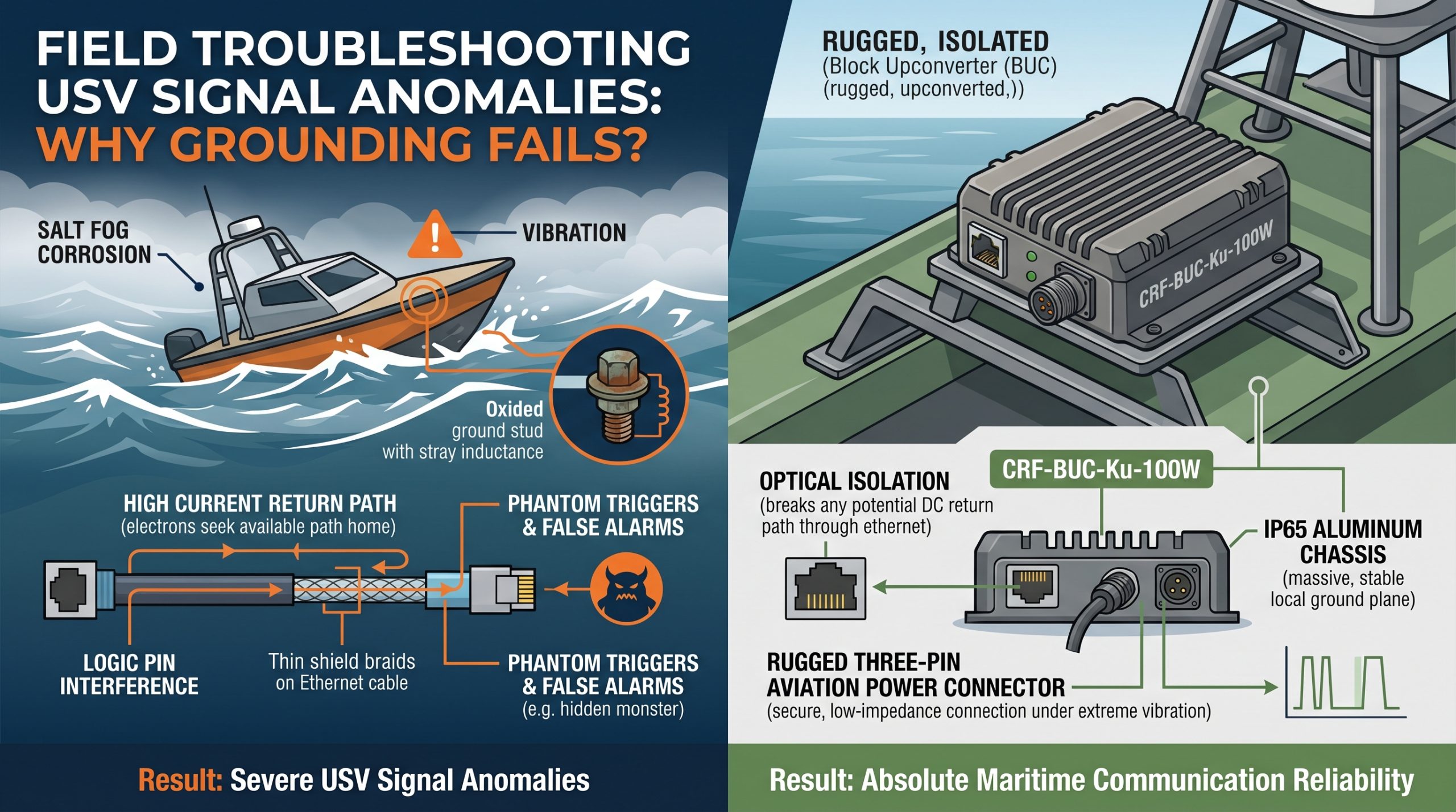
Your Unmanned Surface Vehicle bobs violently within choppy saltwater. Sudden communication drops plague your mission. An intermittent fault triggers autonomous return protocols prematurely. Here is the deal: software developers initially blame messy code. Hardware engineers suspect power amplifier thermal shutdown. Reality proves far more insidious. A hidden monster lurks within your system architecture. Large current returns flowing through poor grounding paths hijack weak logic pins. This phenomenon creates phantom triggers. I have spent two decades chasing these specific RF phantoms across marine platforms. We will dissect this failure mechanism using raw physics. No marketing fluff exists here. Just pure engineering truth.
2 What Causes USV Signal Anomalies in Rough Seas?
Unmanned marine vessels operate within unforgiving environments constantly. Salt fog degrades exposed chassis connections rapidly. High-frequency hull vibrations loosen grounding straps over extended periods. These physical degradations inevitably lead toward severe USV signal anomalies. Marine deployments demand absolute hardware resilience from every component. Standard commercial amplifiers cannot survive such brutal mechanical stress. Your Vector Network Analyzer might display collapsing high-frequency traces during initial bench tests. Field reality hits much harder than controlled laboratory environments. What is the real story? An oxidized ground stud introduces stray inductance immediately. This parasitic impedance blocks high-current return paths completely. RF power modules draw massive transient currents during burst transmissions. When that 450W power demand hits, electrons seek any available path home. They bypass degraded main grounds entirely. Parasitic paths through fragile control interfaces become their new highway. This chaotic electron migration corrupts sensitive control lines instantly. We see this daily when consulting for maritime defense contractors. Those symptoms look exactly like software crashes. However, root causes remain purely electrical. Proper diagnosis requires looking past digital screens toward physical metal.
Symptoms and Root Causes Analysis
| Symptom Observed | Initial Misdiagnosis | Actual Physical Root Cause |
| Intermittent Ethernet drops | Bad network switch | Ground loop current over RJ45 shield |
| Spurious temperature alarms | Faulty thermal sensor | Ground bounce shifting ADC reference |
| Sudden RF power reduction | Transistor degradation | High VSWR from vibration-loosened waveguide |
| Complete system reboot | Software memory leak | Massive DC voltage sag from stray inductance |
3 How Does Poor System Grounding Create Large Current Returns?
A 100W Block Upconverter demands significant DC power continuously. Our CRF-BUC-Ku-100W unit consumes 450 watts typically at 48 volts. That translates into substantial instantaneous current spikes during transmission bursts. Proper system architecture routes this current safely back via massive ground planes. Consider this fact: electrons always follow paths of least resistance. A corroded hull connection increases main return path impedance significantly. High-frequency signals treat this stray inductance like a solid brick wall. Those large return currents must find another route quickly. They divert through thin shield braids wrapping your Ethernet cables. They push violently through RJ45 connector housings. They even travel via serial communication logic grounds. We measure these rogue currents using precision current probes clamped around control wiring. An oscilloscope captures horrifying transient voltage spikes riding on supposedly clean DC lines. These massive current loops induce strong magnetic fields nearby. Those magnetic fields couple directly into nearby sensitive circuitry. Your beautiful RF architecture becomes a chaotic noise generator. USV signal anomalies multiply exponentially as mechanical grounding integrity worsens.
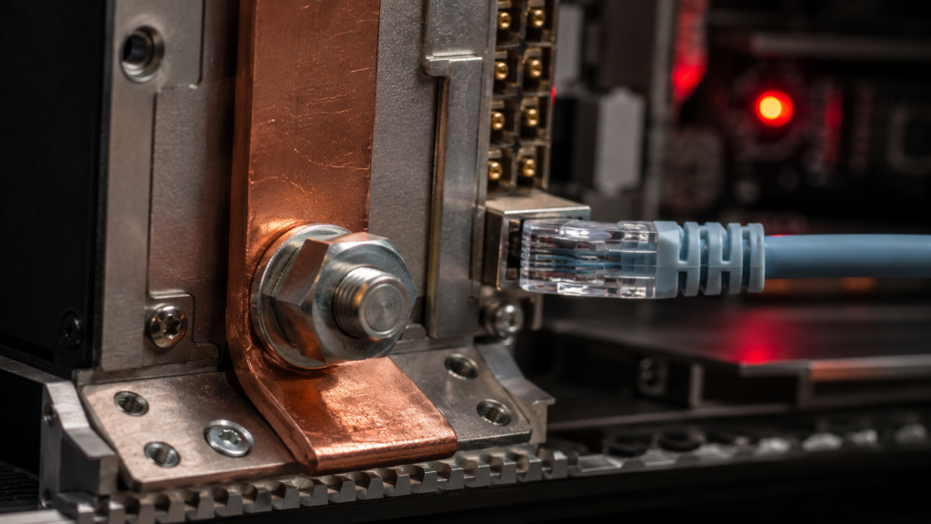
Measured Ground Loop Currents
| Measurement Location | Expected Current | Measured Fault Current | Impact |
| Main Chassis Ground Strap | 10.0 A | 1.5 A | High resistance at hull joint |
| RJ45 Ethernet Shield | 0.0 A | 4.5 A | Packet loss and CRC errors |
| RS-485 Logic Ground | 0.0 A | 2.8 A | Phantom alarm triggers |
| 48V Return Wire | 10.0 A | 8.2 A | Voltage sags during burst |
4 Why Do Weak Current Pins Suffer from Mis-triggering?
System integrators often overlook microscopic details within complex architectures. Modern RF amplifiers utilize low-voltage TTL or CMOS logic for alarm monitoring. These weak current pins operate on tiny voltage thresholds. A mere 3.3V differential dictates a logic high state. Here is the kicker: those stray return currents elevate your local ground potential. We call this phenomenon ground bounce in our industry. When a 10-ampere transmission burst diverts through a 0.5-ohm parasitic path, ground potential shifts by 5 volts. Your microcontroller still outputs 3.3V relative to its local reference. That receiving chip sees a negative voltage relative to newly elevated grounds. This tricks microprocessors into registering false alarms instantly. Thermal fault sensors trigger without actual heat buildup. VSWR protection circuits trip despite perfect antenna matching. Your control computer receives a barrage of false error codes. It shuts down critical RF payloads defensively. Engineers waste weeks rewriting software algorithms trying unsuccessfully mask these hardware-induced USV signal anomalies. Software cannot fix broken physics. You must address electrical architecture at its mechanical source.
Logic Pin Threshold Vulnerabilities
| Logic Family | Nominal High Threshold | Vulnerability Threshold (Ground Bounce) | Resulting Action |
| 3.3V CMOS | > 2.0V | 1.5V shift | False logic low |
| 5.0V TTL | > 2.4V | 2.0V shift | Phantom trigger |
| Analog Sensor | 10mV / Degree | 50mV noise injection | Fake 5-degree spike |
| Mute Pin | Active Low | 1.0V shift | Accidental transmitter shutdown |
5 How Can the CRF-BUC-Ku-100W Resolve These USV Signal Anomalies?
Our factory spent thirty years perfecting RF hardware manufacturing. We employ 400 specialists dedicated toward eliminating these exact field failures. Our CRF-BUC-Ku-100W design specifically mitigates maritime ground loop hazards. Ready for the good part? We isolated all communication interfaces mechanically and electrically. That RJ45 aviation connector features advanced optical isolation techniques natively. This breaks any potential DC return path through your ethernet cables completely. Power delivery utilizes a rugged three-pin aviation connector. This guarantees a secure, low-impedance connection even during extreme hull vibrations. Our unit operates smoothly across a wide 36 through 72 volt range. This wide tolerance absorbs ground-bounce induced voltage sags effortlessly. Integrated receive rejection filtering prevents out-of-band noise from compounding your USV signal anomalies. Our heavy-duty IP65 aluminum chassis provides a massive, stable local ground plane. We mandate strict torque specifications for all chassis mounting points. This prevents vibration-induced impedance changes over extended deployments. Our engineering truth dictates that robust mechanical design solves complex electrical problems permanently.
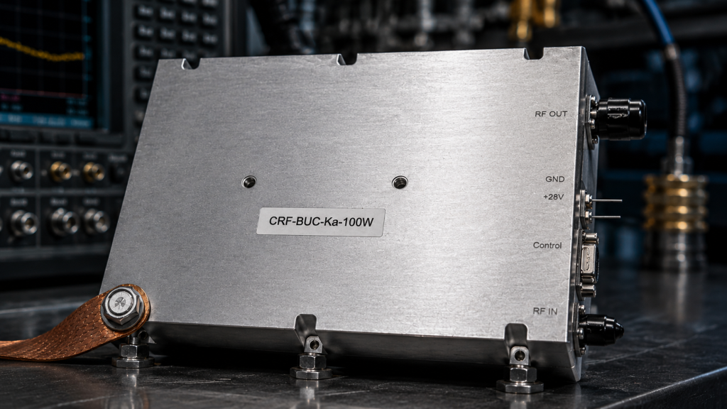
CRF-BUC-Ku-100W Key Specifications
| Parameter | Minimum | Typical | Maximum |
| RF Frequency Range | 13.75 GHz | – | 14.5 GHz |
| Saturated Output Power | 50 dBm | – | – |
| Small Signal Gain | 68 dB | – | – |
| Supply Voltage | 36 V | 48 V | 72 V |
| Power Consumption | – | 450 W | – |
6 What Are the Field Troubleshooting Steps for Grounding Issues?
Field troubleshooting demands rigorous, logical procedures. Never guess when tracking USV signal anomalies. Grab your oscilloscope and a high-bandwidth current probe. Let that sink in: your standard multimeter cannot capture microsecond transient spikes. First, clamp your current probe around that RJ45 communication bundle. Trigger your transmitter into a dummy load. If you read anything above a few milliamperes during transmission, you have a ground loop. Second, probe voltage potentials between your BUC chassis and battery negative terminals. A solid ground yields zero volts AC and DC. Any measurable voltage difference indicates high impedance within your main return path. Third, inspect every physical connection point visually. Look for galvanic corrosion between dissimilar metals. Saltwater accelerates this destructive process rapidly. Clean oxidized surfaces using abrasive pads thoroughly. Apply conductive marine-grade grease before reassembling those joints. These raw physical steps cure ninety percent of phantom logic triggers. Stop chasing ghosts in your software code. Fix that metal first.
Field Troubleshooting Checklist
| Step | Action Required | Equipment Needed | Success Criteria |
| 1 | Measure RJ45 cable shield current during TX | Current Probe + Oscilloscope | < 5 mA peak |
| 2 | Check voltage drop across chassis ground strap | Digital Multimeter | < 0.1 V DC |
| 3 | Inspect waveguide flange mating surfaces | Visual Inspection / VNA | No pitting, Return Loss < -15dB |
| 4 | Verify power supply voltage sag during burst | Oscilloscope | Minimum 36V maintained |
7 How Does CorelixRF Ensure Reliability for System Integrators?
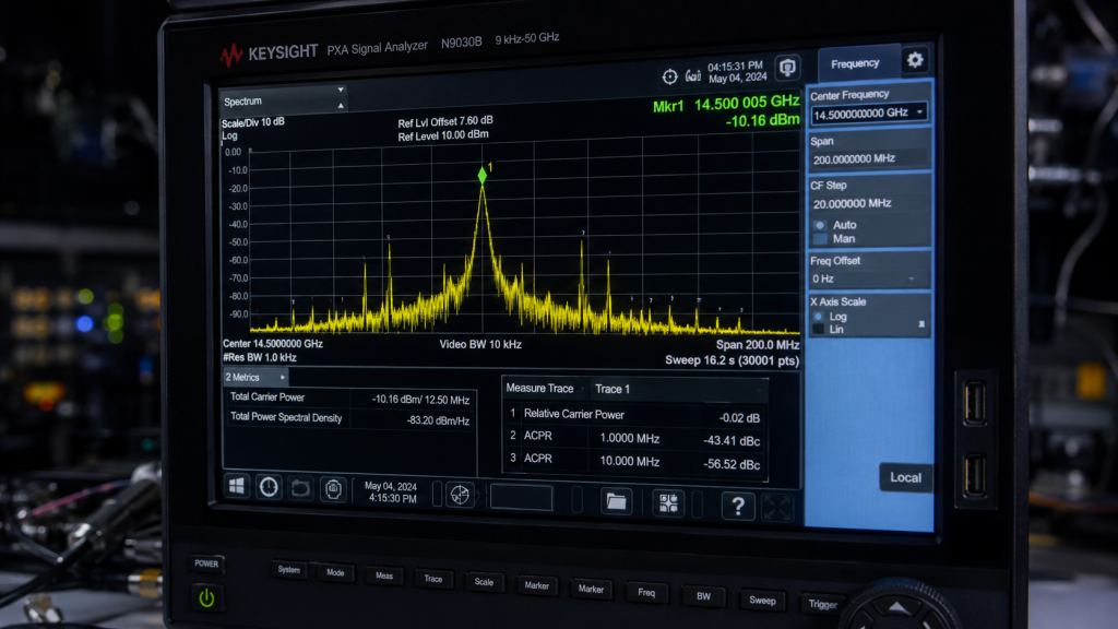
Defense contractors and system integrators require absolute predictability. We build predictability into every module leaving our factory floor. We test every CRF-BUC-Ku-100W unit under brutal thermal conditions. That operating range spans negative 40 through positive 60 degrees Celsius. We push saturated output power beyond 50 dBm continuously. This is where it gets interesting: our test benches replicate harsh maritime ground loop scenarios intentionally. We inject massive common-mode noise into power lines. We verify that phase noise remains ultra-low, hitting negative 95 dBc/Hz at 100KHz offset. Spurious emissions stay firmly below negative 55 dBc. We measure transmit in-band noise meticulously. Our rigorous GJB 9001C quality framework leaves zero room for error. Real-world engineering requires realistic lab-based testing. We supply detailed test data and pattern files for every project review. Integrators deserve transparent metrics, not empty promises. We deliver pure performance backed by massive manufacturing scale.
8 What Should Procurement Engineers Check Before Deployment?
Sourcing RF components requires deep technical scrutiny. Procurement teams often fall into dangerous traps buying commercial off-the-shelf equipment. Standard gear fails spectacularly aboard USVs. You might be wondering: what specifications actually matter? First, demand IP65 environmental protection minimum. Salt spray kills unprotected circuitry within days. Second, verify mechanical connector types. Standard N-type connectors fail under constant vibration. Our N-F input and WR75 output flanges provide rock-solid mechanical stability. Third, check power interface specifications. A flimsy terminal block will cause USV signal anomalies immediately. We use robust aviation connectors exclusively. Fourth, review cooling mechanisms. Our 225 by 151 by 141 millimeter package incorporates high-efficiency air cooling. It dissipates 450 watts of heat effectively. Never accept AI-estimated datasheets from unverified vendors. Demand empirical measurement data. Your entire maritime mission depends on these specific physical tolerances. Quality RF manufacturing demands extreme attention toward microscopic mechanical details.
9 How Do You Validate Fixes Using Oscilloscopes and SWR Meters?
Verification separates true engineers from mere technicians. You cleaned those grounds and installed a CRF-BUC-Ku-100W. Now you must prove those USV signal anomalies vanished. Connect a directional coupler between your BUC output and antenna. Attach an SWR meter or spectrum analyzer. Listen closely: monitor reflected power during full 100W continuous wave transmission. Input/Output VSWR must remain tightly controlled around 1.35. Any sudden spike indicates arc-over within waveguide structures. Next, attach oscilloscope probes onto alarm logic pins. Set trigger modes for capturing single-shot negative-going transients. Fire a rapid sequence of RF bursts. A properly grounded system maintains flat, stable 3.3V logic levels. No spikes, no dips, no phantom triggers exist. That noise floor should remain perfectly flat. This empirical validation builds supreme confidence. You can now sign off on vessel deployment. You conquered physics through precise measurement and proper hardware application.
10 What Are the Long-Term Benefits of Proper RF Architecture?
Investing time into perfect grounding pays massive dividends. Vessels stay deployed longer without requiring emergency maintenance trips. Mean time between failures increases dramatically. The bottom line is: proper physical architecture prevents cascading electronic failures. Your high-value satellite communication links remain stable through violent storms. That CRF-BUC-Ku-100W delivers its rated 50 dBm output reliably year after year. System integrators build stronger reputations by delivering bulletproof platforms. Our thirty years of RF manufacturing experience proves this daily. We see clients transition from constant firefighting toward strategic expansion. They stop wasting engineering hours debugging ground loops. They start developing next-generation autonomous features instead. Physical engineering truth forms bedrock for every successful technological advancement. Master those electrons, secure your grounds, and your maritime communication networks will dominate any harsh environment.
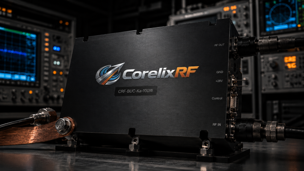
USV signal anomalies frequently stem from poor grounding causing massive return currents. These currents disrupt weak logic pins, creating phantom errors. Upgrading toward mechanically robust CRF-BUC-Ku-100W hardware eliminates these paths through superior isolation. Secure physical connections, validate with oscilloscopes, and achieve absolute maritime communication reliability today.
FAQ
Q1: What causes USV signal anomalies in rough seas?
Salt spray corrosion and severe hull vibrations degrade main grounding straps. This forces large return currents through weak communication pins, causing false triggers.
Q2: How does the CRF-BUC-Ku-100W prevent ground loops?
It utilizes optically isolated RJ45 communication ports and heavy-duty three-pin aviation power connectors. This mechanical isolation breaks stray electrical paths effectively.
Q3: What tools are required for field troubleshooting grounding issues?
You need a high-bandwidth oscilloscope, a precision current probe, and a Vector Network Analyzer. A standard multimeter cannot detect high-speed transient spikes.
Q4: Why do weak current pins suffer from mis-triggering?
Massive RF transmission currents divert through parasitic paths, elevating local ground potentials. This ground bounce tricks microcontrollers into registering false logic states.
Q5: How can procurement engineers ensure USV communication reliability?
They must demand IP65-rated enclosures, rugged aviation connectors, and transparent empirical test data from established RF manufacturers with proven field experience.
Authorized RF engineering and compliance review
For regulated RF systems, this page should be used as an engineering and compliance review path, not as a public deployment checklist. CorelixRF starts with authorization status, operating region, frequency plan, output limit, antenna interface, safety controls, thermal limits and acceptance documents.
- RFQ checklist – send the data buyers usually forget, including band, power, duty cycle, interface and test standard
- delivery documentation – check what documents can support incoming inspection, FAT review and long-term maintenance
- quality and certification review – review the quality and compliance evidence before the project moves into procurement
- RF front-end platform – compare the RF chain as a system instead of selecting one isolated module
- RF configurator – turn frequency, power, thermal and interface requirements into a first configuration brief
- case studies – review similar engineering paths before sending an RFQ
- engineering contact – send the application notes, block diagram or target specification to engineering sales
This keeps the discussion inside lawful, authorized RF programs while still giving procurement teams a clear way to request amplifier, antenna, SDR source, documentation and factory review.