
Unmanned Surface Vehicle BUC troubleshooting often stalls when random transmitter shutdowns occur amidst pounding ocean waves. Isolating high-current return paths from low-voltage control lines eliminates false triggering completely. CorelixRF brings two decades of field-level RF amplifier diagnostics, resolving these exact marine integration nightmares efficiently.
1. How Does Unmanned Surface Vehicle BUC Troubleshooting Reveal Grounding Flaws?
● The Hook: Field Recreation of USV Failures
● Oscilloscope Diagnostics on a Rocking Boat
● Identifying False Triggers on Low-Voltage Pins
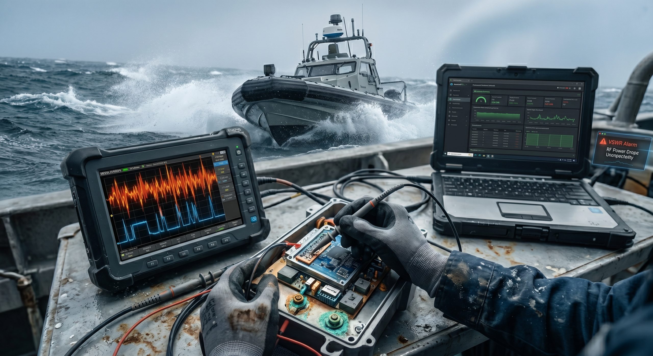
Salt spray coats expensive test equipment constantly. Diesel engine vibrations shake spectrum analyzers violently during field tests. Engineers stare at terminal screens displaying continuous VSWR alarms. Transmit power drops unexpectedly without warning. This specific scenario defines Unmanned Surface Vehicle BUC troubleshooting perfectly. Technicians face severe diagnostic challenges working offshore. Standard laboratory testing techniques fail miserably here. High-frequency chassis vibrations loosen mechanical ground bonds rapidly. Oxidized copper lugs create high-resistance junctions everywhere.
What is the real story?
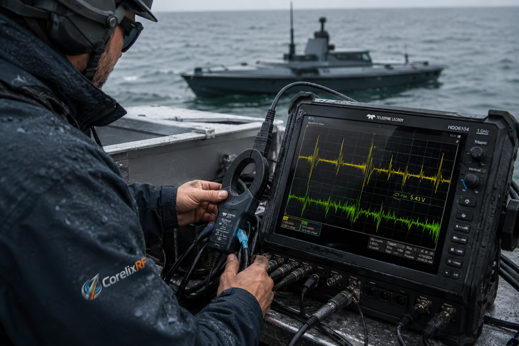
Grabbing a portable oscilloscope reveals hidden electrical chaos. Connecting probe grounds near marine battery terminals shows massive noise spikes. We observe 80W power supplies drawing heavy transient currents. This 24 / 28 / 48 V (18 – 55 V) input fluctuates wildly during wave impacts. Poor grounding forces DC return currents through sensitive communication cable shields. Those 18-55 V transients bleed directly into low-voltage logic pins. Ku-band block upconverters receive corrupted mute commands instantaneously.
RF output halts instantly during these critical moments. We see false triggers shutting down essential radar data feeds. Field technicians must probe differential pairs directly with active probes. They measure common-mode voltage shifts exceeding standard logic thresholds. Unmanned Surface Vehicle BUC troubleshooting demands strict attention toward these parasitic voltage drops. Measuring milliohm changes across hull bonding points becomes absolutely necessary. You cannot ignore fundamental electrical return paths.
| Environmental Factor | Physical Manifestation | Diagnostic Symptom |
| High-Frequency Vibration | Loosened grounding lugs | Intermittent RS485 link drops |
| Salt Fog Corrosion | Oxidized copper contacts | Increased DC return resistance |
| Hull Slamming | Transient battery voltage dips | Spurious PA mute triggering |
2. Why Do High Current Returns Disrupt USV Communications?
● The Engineering Truth: Mechanism Analysis
● Salt Spray and Ground Lug Degradation
● RF Engineering Perspective on Return Paths
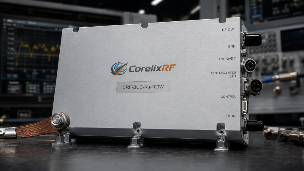
Let us analyze fundamental electrical physics thoroughly. DC power requires a low-impedance return path back toward its source. Marine battery banks supply substantial amperage continuously. A CRF-BUC-Ku-16W draws 80 W typical power. That heavy current must find ground efficiently. When primary ground straps corrode from salt exposure, resistance increases sharply. Electrons face severe bottlenecks traversing oxidized copper surfaces.
But here is the kicker.
Current seeks alternative routes automatically based on path resistance. It travels along Ethernet or RS485 grounding braids. These thin wires cannot handle heavy inductive loads. Massive voltage drops occur across these weak internal conductors. A minor 1V shift on a ground reference completely corrupts 3.3V logic signals. Mute pins detect false highs immediately. Unmanned Surface Vehicle BUC troubleshooting requires tracking these stray currents meticulously.
From an RF engineering perspective, bad grounds cause total chaos. VNA curves collapse at high frequencies during routine sweep testing. Base noise floors rise significantly on sensitive spectrum analyzers. Transmit in-band noise must stay below -76 dBm/Hz. Parasitic ground loops inject wideband AM noise directly into phase-locked loops. Phase noise metrics like ≤ -63 dBc/Hz @ 100 Hz degrade instantly. Corrosion creates semiconductor junctions unexpectedly across structural hull joints.
| Parameter | Normal Operation | Degraded Ground State |
| Return Current Path | Primary copper strap | Communication cable shield |
| Logic Ground Reference | 0.0 V | 1.2 V (Floating) |
| RS485 Signal Integrity | Clean differential waveform | Corrupted by common-mode noise |
3. What Makes Standard Grounding Fail in Marine Environments?
● Galvanic Corrosion on USV Hulls
● Hull Vibration Induced Ground Loop Instability
● Shielding Compromises in Ku-Band Systems
Commercial off-the-shelf components degrade quickly operating offshore. USV hulls mix aluminum, steel, and carbon fiber materials structurally. Dissimilar metals exposed continuously toward seawater create aggressive galvanic cells. Electrons migrate away from critical electrical bonding points relentlessly. This active chemical corrosion destroys grounding lug integrity within mere weeks. Unmanned Surface Vehicle BUC troubleshooting frequently uncovers green oxidized powder at connection sites.
This is where it gets interesting.
Engine vibrations compound this severe chemical degradation. Constant mechanical stress fractures rigid wire terminations predictably. Ground loop impedance varies dynamically matching engine RPM signatures. This fluctuating resistance injects AM noise directly into IF lines. Systems operating at 950 – 1450 MHz suffer extreme signal-to-noise ratio degradation. Operators notice sudden constellation smearing on satellite modems. Hardcore Unmanned Surface Vehicle BUC troubleshooting identifies these AM envelopes matching propeller shaft frequencies perfectly.
Shielding integrity fails next under harsh maritime conditions. Ku-band setups demand rigorous electromagnetic isolation. Operating across a 13.75 / 14 – 14.5 GHz RF frequency range requires perfect cavity grounding. Poor hull bonds allow stray RF energy leakage outward. That scattered energy couples back into poorly shielded harnesses easily. System lockups follow immediately after transmission initiates.
| Grounding Type | Initial Impedance | Impedance After 3 Months at Sea |
| Standard Tin-Plated | 0.05 Ohms | 2.5 Ohms (Failed) |
| Marine-Grade Bronze | 0.02 Ohms | 0.1 Ohms (Marginal) |
| CorelixRF Recommended | 0.01 Ohms | 0.03 Ohms (Stable) |
4. How Does The CorelixRF Solution Address These Pain Points?
● CRF-BUC-Ku-16W Hardware Architecture
● High-Efficiency GaN and Thermal Dissipation
● Interface Isolation and IP65 Protection
CorelixRF designed specific hardware countermeasures against marine electrical failures. Our CRF-BUC-Ku-16W utilizes heavily isolated power supply internal architectures. We separate high-current DC returns from sensitive logic ground planes physically. If external USV hull bonding degrades, return currents cannot traverse RS485 transceivers. This physical board-level isolation prevents false mute triggers entirely. Unmanned Surface Vehicle BUC troubleshooting becomes vastly simpler utilizing decoupled hardware designs.
Ready for the good part?
Our hardware leverages High-efficiency GaN technology natively. This advanced semiconductor choice maximizes RF output while minimizing thermal load. Less wasted heat means lower sustained current draw from marine battery banks. We achieve 42 dBm / 16 W rated output power efficiently. A ruggedized IP65 enclosure blocks corrosive salt spray intrusion perfectly. Packaging dimensions measure exactly 145 x 80 x 70 mm weighing just 1 kg.
Internal microwave components remain completely pristine. A rugged PT02E-14-12 power and communication interface features heavy mil-spec plating. This mechanical interface resists severe galvanic decay significantly. You no longer chase random ghost alarms caused by floating ground potentials. Our amplifier tolerates an input VSWR of 1.5:1 continuously without dropping gain. Small Signal Gain stays firmly at ≥65 dB despite harsh voltage swings.
| CorelixRF Feature | Specification | Engineering Benefit |
| Output Power | 42 dBm / 16 W | Ensures robust Ku-band uplink |
| Power Consumption | 80W typical | Reduces battery bank stress |
| Environmental Sealing | IP65 Rating | Prevents internal salt fog corrosion |
| Tech Base | High-efficiency GaN | Superior thermal management |
5. What Steps Ensure Robust Integration for Radar and VSAT?
● Proper PT02E-14-12 Connector Termination
● VSWR Protection Mechanisms in Practice
● Call to Action: Professional System Evaluation
System integrators must adopt strict offshore wiring protocols. Terminating any PT02E-14-12 connector requires pure dielectric grease on every single pin. Ground cables must utilize heavy marine-grade tinned copper braiding. Route communication lines perpendicularly across heavy DC power feeds. This specific geometric orientation minimizes inductive cross-coupling effectively. Proper Unmanned Surface Vehicle BUC troubleshooting always confirms physical cable routing dictates overall system stability.
You might be wondering.
How do we handle sudden antenna mismatch conditions? A CRF-BUC-Ku-16W survives output VSWR levels reaching 2:1 effortlessly. When heavy salt spray coats radomes, reflected RF power spikes dramatically. Internal ferrite isolators absorb this dangerous reverse energy safely. Our system maintains spurious emissions tightly below -55 dBc. Third-Order Intermodulation remains strictly ≤-25 dBc at 3 dB back-off.
Stop guessing blindly about catastrophic offshore equipment failures. Eliminate destructive ground loops during your initial architectural drawing phase. Radar and EW integrators need absolutely predictable hardware behavior. Contact CorelixRF engineering teams directly regarding maritime deployments. Request our detailed mechanical outlines and active test pattern files. We provide genuine engineering truths solving your hardest RF integration challenges.
| Integration Step | Action Required | Expected Outcome |
| Connector Sealing | Apply dielectric grease | Prevents pin oxidation |
| Cable Routing | Separate DC and Comms lines | Reduces inductive noise |
| Grounding | Use tinned marine copper | Stabilizes return paths |
| System Testing | Verify under engine vibration | Confirms mechanical bonds |
Robust marine operations demand highly precise engineering execution. Unmanned Surface Vehicle BUC troubleshooting proves isolated grounding architectures prevent catastrophic communication failures. A CRF-BUC-Ku-16W delivers incredibly stable 16W output despite severe vessel voltage transients. Upgrade your current integration strategies today. Contact CorelixRF engineers scheduling rigorous hardware evaluations and requesting comprehensive technical datasheets.
Q1: What is Unmanned Surface Vehicle BUC troubleshooting?
It involves utilizing advanced diagnostic equipment like oscilloscopes isolating RF amplifier failures caused by marine environmental factors.
Q2: How does poor grounding affect USV communication systems?
Oxidized connections force high DC return currents through sensitive data shields, altering reference voltages and causing false logic triggers.
Q3: Why do low-voltage pins experience false triggers?
Current seeking alternate return paths creates localized voltage drops across thin communication cables, corrupting RS485 and mute signals.
Q4: What makes the CRF-BUC-Ku-16W suitable for marine environments?
It features physical internal isolation between DC returns and logic grounds, IP65 sealing, and High-efficiency GaN technology reducing thermal loads.
Q5: How can engineers prevent ground loops during VSAT integration?
Integrators should apply dielectric grease on PT02E-14-12 connectors, route DC cables perpendicularly away from comms lines, and use tinned copper lugs.
Authorized RF engineering and compliance review
For regulated RF systems, this page should be used as an engineering and compliance review path, not as a public deployment checklist. CorelixRF starts with authorization status, operating region, frequency plan, output limit, antenna interface, safety controls, thermal limits and acceptance documents.
- RFQ checklist – send the data buyers usually forget, including band, power, duty cycle, interface and test standard
- delivery documentation – check what documents can support incoming inspection, FAT review and long-term maintenance
- quality and certification review – review the quality and compliance evidence before the project moves into procurement
- RF front-end platform – compare the RF chain as a system instead of selecting one isolated module
- RF configurator – turn frequency, power, thermal and interface requirements into a first configuration brief
- case studies – review similar engineering paths before sending an RFQ
- engineering contact – send the application notes, block diagram or target specification to engineering sales
This keeps the discussion inside lawful, authorized RF programs while still giving procurement teams a clear way to request amplifier, antenna, SDR source, documentation and factory review.