
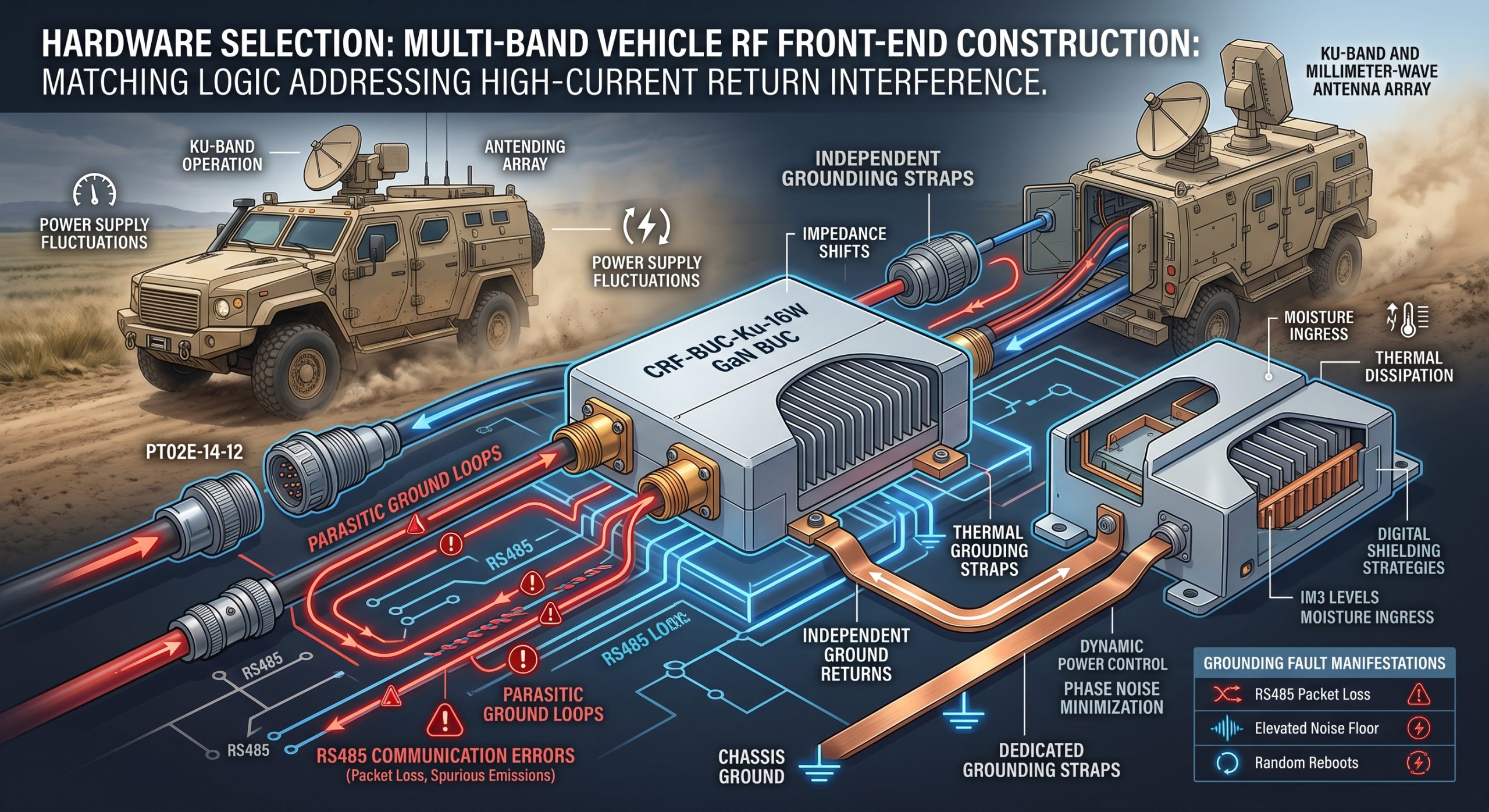
Multi-band Vehicle RF Front-end Construction: Matching Logic Addressing High-Current Return Interference. Consider an actual field scenario. System integrators often face catastrophic transmission drops inside mobile satellite communication platforms. You fire up your millimeter-wave array, and suddenly, RS485 communication lines throw continuous errors. Such faults stem directly from poor system chassis grounding, forcing heavy direct current returns through fragile data paths. Addressing these parasitic loops forms a critical prerequisite establishing stable Ku-band operations. Our discussion tackles exact physical mechanisms behind these failures.
1. What physical mechanisms drive ground return interference during vehicle deployment?
Identifying Parasitic Current Paths
Here lies an undeniable truth. Mobile platforms possess inherently noisy electrical environments. Heavy diesel alternators generate massive voltage ripples across any metallic chassis. When engineers integrate a 42 dBm transmission module like our CRF-BUC-Ku-16W, they frequently underestimate dynamic current consumption profiles. A device pulling 80 W typical power at 24 V requires exceptionally clean, physically isolated return paths. If heavy DC power returns share a common copper plane with weak logic pins, massive voltage drops occur across minimal resistive traces. Ohm’s law dictates that even fifty milliohms of parasitic resistance will elevate local ground potentials massively during peak envelope power transmission bursts. Such elevated potentials push digital thresholds beyond safe operating areas. Our three decades of manufacturing expertise reveal that commercial-grade connectors fail under continuous high-frequency vibration found across terrestrial vehicles. We utilize robust PT02E-14-12 power and communication interfaces, physically separating high-current supplies from sensitive monitoring lines. System architects must measure shield continuity continuously. Otherwise, your spectrum analyzer will display unexplainable noise floors rising alongside transmit output spikes. High-current loops create magnetic fields inducing noise voltages onto adjacent sensitive traces. Managing these paths dictates ultimate mission success.
Grounding Fault Manifestations
| Fault Manifestation | Root Cause Analysis | Engineering Mitigation |
| RS485 Packet Loss | High-current ground loop | Isolated shielding implementation |
| Elevated Noise Floor | Chassis voltage ripples | Independent return paths |
| Random System Reboots | Supply voltage droop | Heavy gauge wire routing |
| Spurious Emissions | Shared DC return planes | Dedicated grounding straps |
2. How do power supply fluctuations degrade RF front-end stability?
Managing Extreme Voltage Swings
What represents our real story? Direct current supplies inside military or commercial vehicles never remain flat. Engines rev, charging circuits engage, causing bus voltages fluctuating wildly. Standard consumer-grade converters struggle managing inputs dropping below 20 V or spiking above 30 V. These massive swings inject amplitude modulation directly onto sensitive Gallium Nitride bias networks. If local oscillator circuits lack extreme line isolation, phase noise degrades rapidly. You might observe a vector network analyzer trace showing gain flatness tearing itself apart across our 13.75 through 14.5 GHz operating band. We engineered our CRF-BUC-Ku-16W input regulation stage accommodating an ultra-wide 18 through 55 V range. This robust architecture guarantees constant 42 dBm saturated output power despite sudden vehicle battery sag. Our internal switching regulators operate far above common IF frequency ranges spanning 950 through 1450 MHz, eliminating harmonic crossover interference completely. When designing your power distribution network, always calculate maximum voltage drops across supply cables. Thicker gauge wire minimizes resistive heating while preventing low-voltage shutdown triggers during cold engine starts. Solid regulation guarantees clean spectrum emissions.
Power Supply Stability Metrics
| Parameter | Standard Commercial Unit | CRF-BUC-Ku-16W |
| Operating Voltage Range | 24 V fixed | 18 – 55 V dynamic |
| Gain Stability (-40 to 60 °C) | ±5 dB | ±2 dB |
| Input Regulation Scheme | Linear LDO | High-frequency Switching |
| Low Voltage Dropout | System Halt at 22 V | Continuous Operation at 18 V |
3. Why do standard matching networks fail under mobile vibration?
Impedance Shifts Under Kinetic Stress
This constitutes where things become interesting. Mobile satellite antennas constantly track moving targets. Mechanical steering or electronic beamforming causes temporary impedance mismatches at your WR75 waveguide output interface. Traditional continuous-wave protection circuits react too slowly when facing rapid phase shifts. Reflected energy travels back into your final GaN amplification stage, creating extreme standing waves. Heat concentrates at microscopic junctions within active transistors. Without immediate detection, thermal runaway destroys expensive semiconductor dies within microseconds. Our engineering teams implemented high-speed directional couplers measuring forward versus reflected power simultaneously. We guarantee stable operation even when facing a 2:1 output VSWR environment. Our control loop reduces drive levels instantly before junction temperatures exceed safe operating limits. Base station integrators must verify waveguide flange mating surfaces continuously. Even slight salt-fog corrosion degrades conductivity, causing reflections that standard protective logic might miss. We seal our IP65 rated enclosures tightly, preventing moisture ingress from shifting resonant frequencies across sensitive microstrip filters. Consistent matching saves expensive hardware.
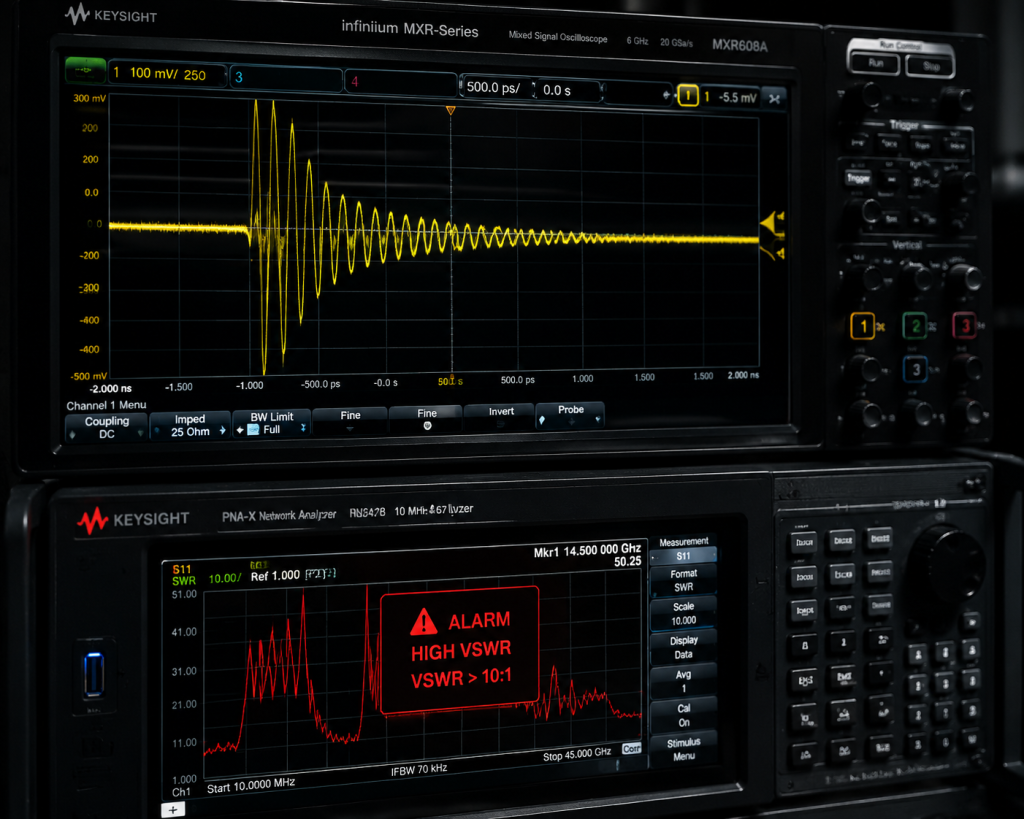
VSWR Protection Dynamics
| Scenario | Detection Speed | System Response |
| Gradual Impedance Drift | Milliseconds | Auto-leveling bias adjustment |
| Sudden Antenna Disconnect | Microseconds | Complete drive stage shutdown |
| 2:1 Output VSWR Condition | Continuous | Safe operation maintained |
| Corroded Waveguide Flange | Real-time monitoring | Forward power scaling |
4. How does our structural design optimize critical thermal dissipation?
Thermodynamics In Confined Spaces
Ready for our good part? Heat represents an ultimate enemy regarding RF reliability. Generating 16 W of clean microwave energy requires burning 80 W typical power as heat. In enclosed vehicular compartments, ambient temperatures easily reach 60 degrees Celsius. Standard extruded aluminum heatsinks lack sufficient surface area supporting convective cooling under zero-airflow conditions. We designed our chassis utilizing advanced thermodynamic modeling, maximizing fin density without compromising mechanical rigidity. Measuring 145 by 80 by 70 millimeters, this compact 1 kg package acts as a highly efficient thermal mass. High-efficiency GaN technology natively supports higher junction temperatures compared against legacy GaAs equivalents. We apply military-grade thermal interface materials between active components and our baseplate, ensuring rapid heat transfer away from sensitive areas. Engineers mounting these units must maintain flat, thermally conductive contact surfaces. Adding external forced air cooling dramatically extends mean time between failures during continuous high-power transmission cycles. Neglecting proper airflow paths will trigger internal sensors, commanding automatic shutdown protocols protecting internal circuitry.
Thermal Management Specifications
| Specification | Value / Method | Operational Impact |
| Package Size | 145 x 80 x 70 mm | Compact integration footprint |
| Total Weight | 1 kg | Minimal payload burden |
| Cooling Methodology | Optimized air cooling | Reliable convective transfer |
| Operating Temperature Range | -40 to 60 °C | Global deployment capability |
5. What integration protocols eliminate RS485 communication misfires?
Digital Shielding Strategies
Let us examine another critical factor. Digital control lines transmitting via RS485 differential pairs offer inherent noise immunity. However, severe common-mode voltage spikes can still exceed transceiver breakdown limits. When high-power RF stages pulse, electromagnetic pulses radiate from poorly shielded cables. These fields couple into nearby Ethernet or serial wires, causing packet loss or complete microprocessor lockup. We mandate shielded, twisted-pair cabling for all PT02E-14-12 interconnects. Grounding both ends of a cable shield might seem logical, but doing so often creates massive ground loops across vehicle chassis potentials. Our recommended practice involves tying shields firmly at your main controller while leaving remote amplifier ends capacitively coupled. This approach bleeds off RF energy while preventing direct current flow through shielding braids. A reliable system demands meticulous attention concerning signal routing paths. Keeping weak-current digital lines physically separated from high-power DC feeds eliminates inductive crosstalk, guaranteeing zero false triggers during critical field operations. Flawless communication requires strict physical layer discipline.
Communication Interface Reliability
| Interface Type | Vulnerability | Recommended Shielding Practice |
| RS485 | Common-mode voltage spikes | Twisted-pair with capacitive grounding |
| Ethernet | Inductive crosstalk | Physical separation from DC lines |
| Analog Monitor | RF ingress | Low-pass filtering at connector |
| Power Feed | High current loops | Dedicated heavy-gauge returns |
6. How do intermodulation distortion limits impact complete link budgets?
Spectral Purity Requirements
Here lies another undeniable truth. Multi-carrier satellite uplinks demand pristine linearity. Driving an amplifier deep into saturation generates third-order intermodulation products. These spurious emissions interfere with adjacent channels, violating strict regulatory masks. A poorly designed front-end forces operators toward massive power back-offs, wasting valuable RF potential. We specify our CRF-BUC-Ku-16W delivering IM3 levels below -25 dBc at just 3 dB back-off. This exceptional linearity stems from optimized bias sequencing and careful load-pull matching across our entire GaN output stage. System planners can allocate link budgets confidently, knowing our module maintains tight spectral purity. When you inject a two-tone test signal, your spectrum analyzer will display incredibly sharp main carriers devoid of wideband noise shoulders. Transmit in-band noise remains strictly suppressed below -76 dBm/Hz. Achieving these metrics requires engineers supplying ultra-clean 10 MHz reference clocks via our IF port. Phase noise present on reference lines multiplies directly up into Ku-band, destroying complete error vector magnitude performance.
7. Why must procurement engineers prioritize rigorous environmental sealing?
Defeating Moisture Ingress
Consider an everyday engineering reality. Vehicle-mounted hardware endures relentless environmental abuse. Highway speeds drive rain, dust, and corrosive road salts directly into exposed equipment bays. A standard vented enclosure provides zero defense against microscopic particulate ingress. Conductive dust settling onto microstrip lines alters impedance parameters, detuning meticulously calibrated matching networks. We encase our CRF-BUC-Ku-16W within a fully sealed, IP65 certified chassis. This hermetic barrier prevents moisture absorption within dielectric substrates, maintaining constant electrical length over years of deployment. We utilize specialized O-rings and environmental gaskets sealing every N-F input connector and data port. Maritime satellite communication applications particularly benefit from our rigorous anti-corrosion treatments applied across all external aluminum surfaces. Field technicians no longer need apply messy conformal coatings during installation. A robust mechanical outline guarantees drop-in replacement compatibility across diverse mounting brackets. Your maintenance crews will appreciate zero required field tuning, slashing operational downtime massively.
8. How do phase noise specifications influence target acquisition speed?
Oscillator Jitter Minimization
You might wonder about this detail. Radar and advanced tracking systems rely heavily upon phase stability. High phase noise effectively smears returned signals across frequency domains, burying small targets beneath local oscillator jitter. We grasp how critical absolute frequency precision acts during mobile operations. Our internal synthesizer architecture guarantees exceptional spectral purity. Phase noise drops below -63 dBc/Hz at 100 Hz offsets, plunging rapidly below -93 dBc/Hz at 100 kHz. Such tight specifications enable rapid coherent integration times within your baseband processors. Achieving these numbers demands zero compromise regarding internal component selection. We isolate noisy digital control circuits physically away from voltage-controlled oscillators using thick metallic shielding walls. Integrators utilizing external 10 MHz references must guarantee zero ground loop currents flow through their coaxial feeds. An interfering hum modulating your reference input will create massive sidebands, completely invalidating our meticulous internal phase noise optimizations. Pure tones guarantee rapid locking.
9. What role do precise gain adjustment steps play during network calibration?
Dynamic Power Control
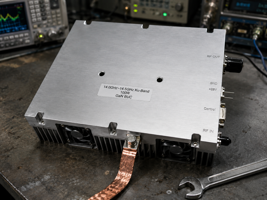
This concept alters traditional paradigms. Satellite networks require dynamic power control managing atmospheric attenuation. Rain fade quickly degrades signal-to-noise ratios, demanding immediate transmit power increases. Conversely, clear skies require power reduction preventing satellite transponder saturation. We incorporated a highly precise digital step attenuator within our RF chain. Operators command a 20 dB gain adjustment range utilizing fine 0.5 dB steps via RS485 or Ethernet interfaces. Our internal microcontrollers compensate for temperature variations automatically, maintaining gain stability within ±2 dB across a grueling -40 through 60 degrees Celsius operating range. You experience consistent small signal gain exceeding 65 dB regardless of environmental extremes. Gain flatness remains incredibly tight, holding ±0.6 dB across any 40 MHz transponder bandwidth. Field engineers aligning vehicle arrays can dial output levels exactly where needed without relying upon bulky external attenuator pads. This integrated approach shrinks total bill-of-materials costs while eliminating multiple potential point-of-failure connector interfaces.
10. How does source factory capability streamline custom RF integration?
Rapid Hardware Iteration
We arrive at our core advantage. Purchasing off-the-shelf components often forces uncomfortable design compromises. Integrators might find perfect electrical specs housed within incompatible mechanical formats. With four hundred dedicated personnel operating our manufacturing facility, we provide unprecedented customization flexibility. Our CRF-BUC-Ku-16W serves as a proven baseline platform. If your specialized radar application demands custom IF frequencies or unique LO configurations, our R&D teams execute rapid hardware iterations. We manufacture these modules under strict ISO 9001 and GJB 9001C quality frameworks. Every unit undergoes rigorous automated testing before shipment. We provide exhaustive test data alongside pattern files, facilitating smooth project reviews. Procuring directly from an original equipment manufacturer eliminates middleman markup while establishing a direct communication line addressing deeply technical integration challenges. We invite you into our laboratories testing these modules under your specific operational loads, proving our engineering truth definitively. Customization empowers dominant market positioning.
Successful multi-band vehicle RF integration demands rigorous attention toward grounding mechanics and power stability. Eliminating high-current return interference prevents catastrophic false triggers across sensitive data lines. A robust hardware design guarantees reliable continuous field operations. Contact our engineering team today requesting exhaustive datasheet specifications addressing your next heavy-duty mobile system deployment.
FAQ Section
- Q1: What represents a primary cause behind RF front-end grounding failures?Heavy direct current returns from high-power amplifiers sharing physical copper planes with sensitive digital logic pins.
- Q2: How does high-current return interference affect system logic?It creates localized voltage drops across resistive traces, pushing digital logic thresholds beyond safe levels, causing packet loss.
- Q3: Why do vehicle vibrations degrade standard matching networks?Vibration loosens commercial-grade connectors, causing sudden impedance shifts creating massive reflected power traveling back toward active amplification stages.
- Q4: What thermal dissipation methods work best for high-power GaN modules?Utilizing high-density finned heatsinks machined from solid blocks, combined with military-grade thermal interface materials transferring heat rapidly.
- Q5: How can integrators prevent RS485 communication misfires?By implementing strict shielded twisted-pair cabling, coupling remote shields capacitively, preventing stray RF energy from corrupting differential data streams.
Translate rugged-site symptoms into a complete RF-chain review
Rugged RF issues often combine grounding, vibration, thermal range, connector retention, signal source stability and amplifier power margin. Share the site condition and acceptance evidence needed before choosing a platform.
Recommended next step: send the operating band, output power target, duty cycle, load condition, control interface, protection or thermal limits and required FAT documents. CorelixRF can review this How to Protect Your Vehicle RF Front-end from Interference? requirement against standard RF amplifier platforms, RF front-end options and controlled customization paths.