
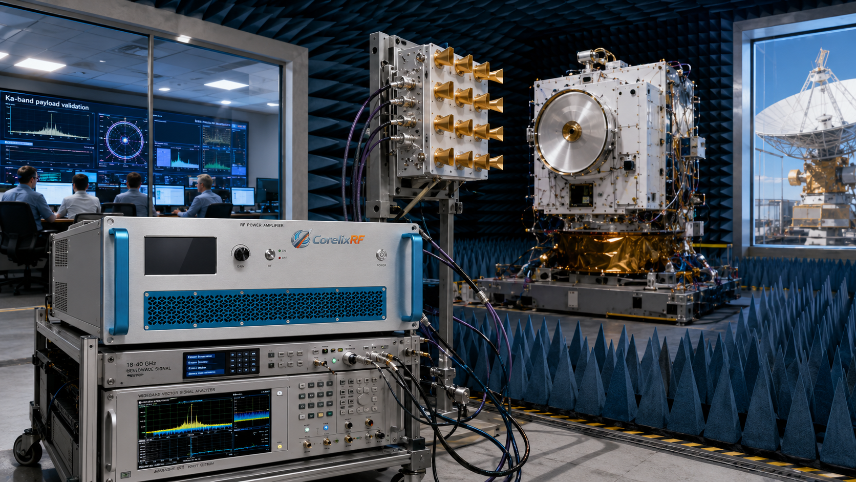
An 18-40 GHz microwave power amplifier is often purchased for Ka-band work, but the amplifier itself is only one part of the problem. At these frequencies, the test setup can become the limiting factor. A good amplifier can still produce poor data if the connectors are worn, the adapter stack is too long, the reference plane is unclear, or the calibration does not include the real loss between the amplifier and the device under test.
This is why an 18-40 GHz amplifier should be specified as part of an OTA, antenna, payload, or component test method. The frequency range reaches into bands used for satellite communications, high-frequency radar development, frequency converter validation, receiver front-end testing, and advanced antenna work. Those applications do not tolerate casual RF handling. Small mechanical differences can create measurable electrical differences.
The first discipline is connector control. Above 18 GHz, connector quality, torque practice, cleanliness, adapter count, and cable bend radius all matter. A connector that looks acceptable by eye may still create ripple, mismatch, or repeatability issues. If the amplifier is used in a shared lab, the team should define who is allowed to mate connectors, what torque tools are used, and how damaged adapters are removed from service.
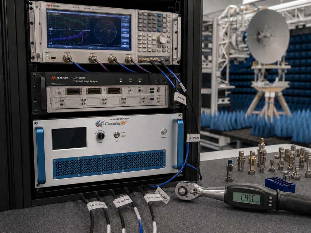
The second discipline is reference-plane clarity. A power number at the amplifier connector does not answer the real test question. For OTA work, the important point may be the antenna input. For probe work, it may be a fixture reference plane. For converter testing, it may be a calibrated input to a module. Every coupler, cable, switch, waveguide transition, and adapter between the amplifier and that point changes the delivered power. The amplifier requirement should be built from that delivered-power calculation.
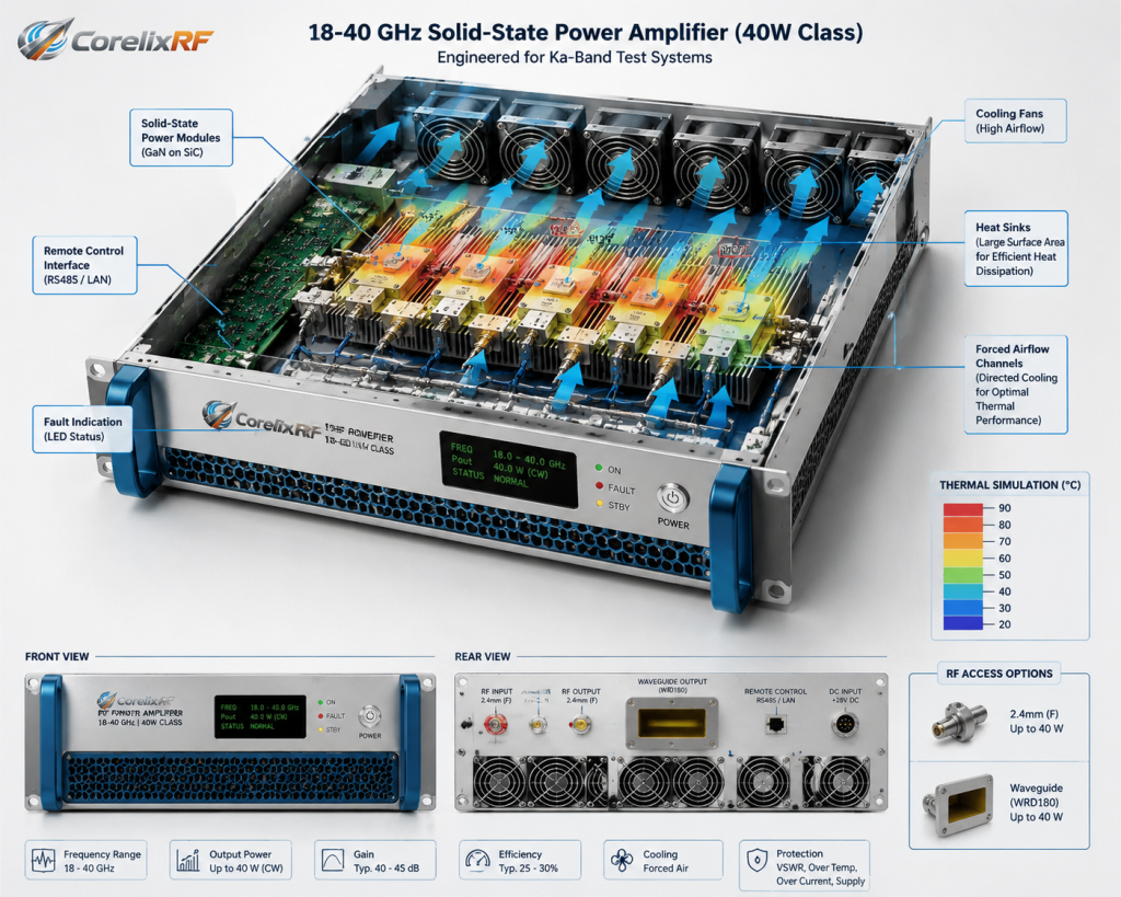
CorelixRF 18-40 GHz amplifier options, including 20 W and 40 W class directions, should be evaluated against that complete path. A 40 W class unit may be useful where fixture loss is high or field generation requires more margin. A 20 W class unit may be better where heat, size, or normal operating power are more constrained. The decision should be tied to the test path, not to a generic desire for the highest wattage.
Ka-band OTA testing adds another layer: measurement repeatability. If an antenna range is being used to compare patterns, gain, or receiver behavior, uncontrolled cable movement can shift results. If the amplifier is moved between benches, the calibration may no longer describe the actual setup. The system should include stable mounting, strain relief, documented cable routing, and a calibration procedure that engineers can repeat.

Waveform details matter as well. A swept-CW test places different demands on the amplifier than a modulated satellite waveform. If the signal has high peak-to-average ratio, the amplifier may need output backoff to avoid compression effects that distort the measurement. If the test is pulsed, duty cycle and thermal conditions should be specified clearly. Without waveform information, an amplifier review is incomplete.
Thermal and fault behavior should not be treated as afterthoughts. High-frequency amplifiers still reject heat, and a compact rack or enclosed station can create temperature rise that affects reliability. The system should define acceptable ambient conditions, airflow clearance, fault response, and whether external monitoring is required. For expensive Ka-band test hardware, reflected-power and mismatch conditions deserve special attention.
The best RFQ for an 18-40 GHz microwave amplifier includes the operating sub-bands, required delivered power, reference plane, connector standard, cable and fixture loss, waveform, duty cycle, cooling constraints, and mismatch risk. That information gives CorelixRF a real engineering picture instead of a short frequency-and-wattage request.
The main lesson is simple: at 40 GHz, the amplifier cannot rescue a loose test method. It can provide the needed microwave power, but the measurement quality comes from the whole chain. When connectors, calibration, reference plane, thermal planning, and waveform requirements are handled together, an 18-40 GHz amplifier becomes a reliable part of a Ka-band test system rather than a source of avoidable uncertainty.