
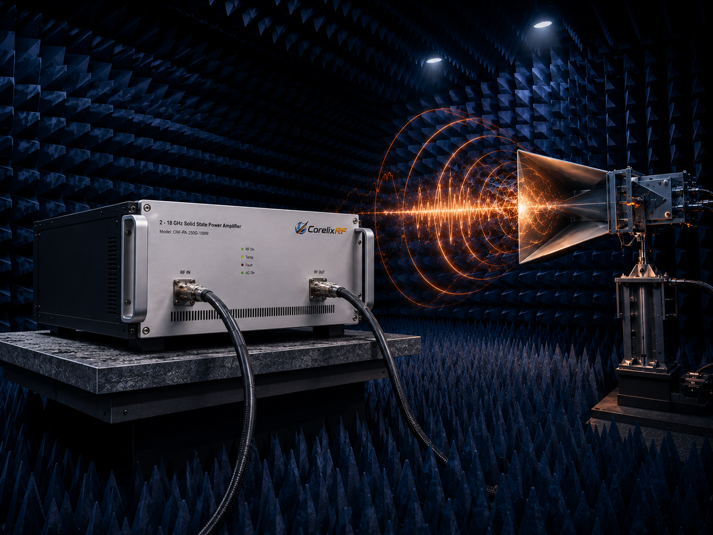
For many RF test benches, the amplifier is not just another rack component. It determines whether the signal chain can cover the required band, keep gain usable across frequency, tolerate mismatch events, and support repeatable measurements without forcing the engineer to swap hardware every time the test condition changes. That is why a 2-18 GHz broadband RF power amplifier is often considered for wideband laboratory systems, microwave device characterization, SDR evaluation, EMC-related work, and general-purpose RF power delivery.
CorelixRF designs solid-state RF amplifiers for engineering teams that need practical frequency coverage, defined output power targets, usable gain, RF connectors that fit the system, and enclosure choices that support integration. This article uses the CorelixRF 2-18 GHz, 20 W class amplifier direction as a reference point and focuses on how to specify the amplifier without overclaiming what the hardware can do.
Why 2-18 GHz Coverage Matters
The 2-18 GHz range spans S-band, C-band, X-band, and part of Ku-band. That makes it valuable when one test platform has to cover multiple programs or when a product team is still refining final operating bands. A narrowband amplifier may offer strong performance in one slice of spectrum, but it can increase system complexity when the test plan moves across several microwave bands.
A broadband amplifier helps reduce switching, recabling, fixture changes, and calibration overhead. For teams comparing antennas, microwave modules, filters, receivers, or SDR front ends, this can shorten the time between experiments. The tradeoff is that broadband amplifiers must be specified carefully. Output power, gain flatness, thermal behavior, and load tolerance can vary across the band, so the useful question is not only “Does it cover 2-18 GHz?” but “Does it meet the required power and gain at the frequencies that matter most?”
Start With Output Power at the Device Under Test
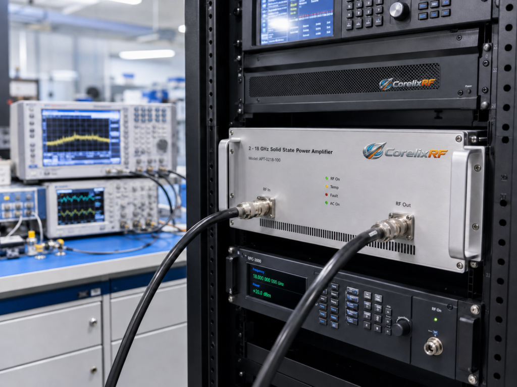
A common mistake is to specify only the amplifier rated output and ignore losses between the amplifier and the device under test. Coaxial cable loss, switches, directional couplers, attenuators, fixtures, and adapters can consume meaningful power at microwave frequencies. At 18 GHz, these losses may be much higher than the team expects if the test setup grew over time.
For a 20 W class 2-18 GHz RF amplifier, calculate the required power at the load first. Then work backward through the cable and fixture loss budget. If the DUT needs a controlled input level rather than maximum power, include headroom for modulation, calibration uncertainty, and protection margin. This approach is more reliable than choosing an amplifier based only on a headline wattage.
Match Gain to the Available Drive Source
Signal generators, SDR transmit chains, and microwave synthesizers do not all provide the same drive level. Some lab sources can deliver enough power to drive a high-gain amplifier comfortably, while compact SDR platforms may need additional gain before the final power stage. The amplifier gain must be considered together with the source output, the desired output level, and any inline attenuation used to improve match or measurement accuracy.
When discussing a broadband RF power amplifier with CorelixRF, provide the available drive level in dBm, the target output power, the frequency points of greatest interest, and whether the signal is CW, pulsed, modulated, or swept. That information helps define whether a standard design is appropriate or whether a custom RF amplifier discussion is more suitable.
Consider Connectors, Cooling, and Protection
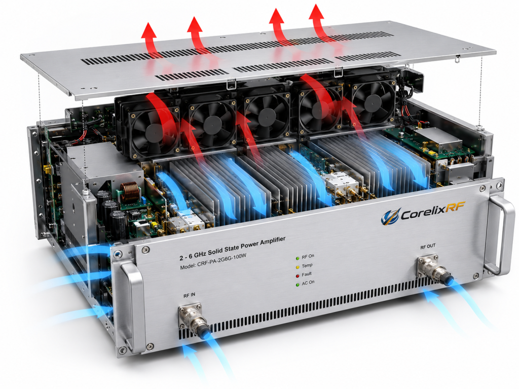
Mechanical and thermal details are often where an otherwise good amplifier choice becomes difficult to integrate. A 2-18 GHz amplifier may use microwave-grade RF connectors and needs a layout that keeps cable runs short, repeatable, and strain-relieved. If the amplifier is going into a rack, enclosure size, airflow direction, control access, and DC power input all matter.
Solid-state RF amplifiers also need thermal planning. The system should allow clean airflow, avoid blocked fan paths, and leave enough space for heat rejection. If the amplifier is used in long-duration sweeps or production-style testing, thermal behavior becomes part of measurement repeatability. Protection features such as over-temperature protection and load mismatch tolerance should be discussed during specification, especially where antennas, fixtures, or unknown loads are involved.
Applications for a 2-18 GHz Broadband Amplifier
A 2-18 GHz amplifier can support several engineering workflows. In EMC and immunity-style setups, it may provide RF power across multiple bands when paired with the appropriate antenna, coupler, and monitoring equipment. In SDR validation, it can help raise a transmit chain to a testable level across wide microwave coverage. In component evaluation, it can drive filters, limiters, mixers, receivers, and antennas under controlled conditions.
It can also be useful for integration labs that support multiple internal programs. Instead of buying a separate amplifier for every band, the lab may use one wideband unit where the output power and gain profile are suitable. The key is to document the real operating points rather than assuming all applications need the same margin.
Specification Checklist for Buyers
Before requesting an RF amplifier review, prepare the following information:
Frequency and Power
List the exact operating band, the target output power at the load, and the required duty cycle. If the system only needs full power in part of the 2-18 GHz range, say so. That detail can influence the recommended configuration.
Input Signal
Provide source power, waveform type, modulation, pulse conditions, and expected test duration. A CW bench test and a pulsed radar-like waveform can place different demands on the amplifier.
System Integration
Document connector preferences, control requirements, cooling constraints, rack or module format, and available power supply rails. These practical details make the difference between a good datasheet match and a deployable amplifier.
Risk Conditions
Mention possible high VSWR, open or short load events, antenna mismatch, operator changes, and long unattended runs. Protection behavior should be part of the conversation for any serious test platform.
FAQ
What is the main benefit of a 2-18 GHz broadband RF power amplifier?
It can cover several microwave bands with one amplifier, reducing hardware swaps and simplifying wideband test setups when the power and gain profile match the application.
Is a 20 W class amplifier always enough for EMC testing?
Not always. EMC setups depend on antenna gain, distance, field-strength target, cable loss, and test standard requirements. The full system budget should be reviewed before selecting output power.
Can a broadband amplifier be used with SDR equipment?
Yes, when the SDR output level, waveform, filtering, duty cycle, and frequency range are compatible with the amplifier input and output requirements.
Should I choose a standard amplifier or request customization?
Use a standard amplifier when the frequency, power, connectors, cooling, and control interface already fit. Request customization when the system has special mechanical, thermal, waveform, or integration constraints.
Conclusion
A 2-18 GHz broadband RF power amplifier is most valuable when it is selected around the complete signal chain, not only the frequency range. By reviewing output power at the load, source drive level, cooling, connectors, protection needs, and test workflow, engineering teams can choose an amplifier that supports repeatable microwave testing with fewer integration surprises.
CTA Button: Request an RF Amplifier Review
2-18 GHz RF Amplifier Engineering Path
For teams turning broadband test requirements into purchasable hardware, compare the RF power amplifier portfolio, review custom RF amplifier options, and align the amplifier with signal source and RF front-end needs before quoting.