
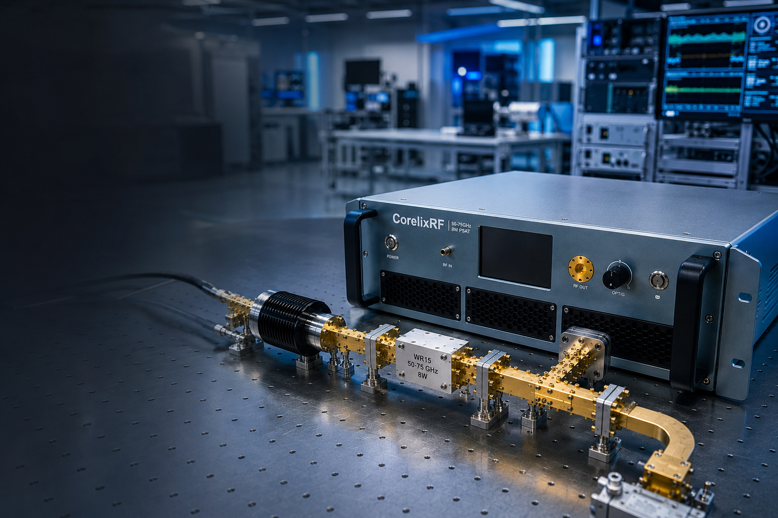
These notes are written from the viewpoint of a bench integration handoff. The CRF-PA-50000M75000M-8W, identified by the local datasheet file as CRF-PA50G75G-8W, is specified for 50-75 GHz operation with 8 W rated output power, WR15 input and output, 39 dB minimum small-signal gain, -10 to +10 dB gain flatness, 15 dB gain control, forced-air cooling, real-time temperature and current monitoring, alarm protection, and a 19-inch 3U package.
A mmWave power amplifier in this range is not installed the same way as a lower-frequency coaxial amplifier. The waveguide path, rack position, handling practice, and measurement reference plane need to be written down before the first serious test run.
Field Note: The Waveguide Path Becomes the Instrument
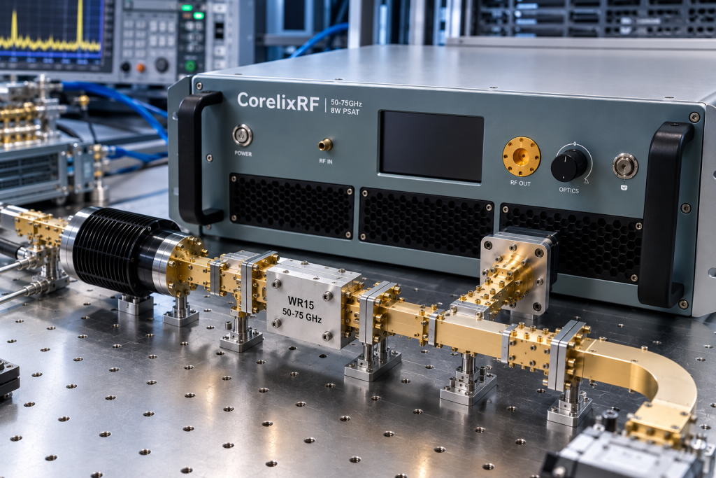
WR15 hardware should be treated as part of the amplifier setup. Record every waveguide section, bend, coupler, transition, load, and antenna connection. If the amplifier moves between benches, keep a known-good path for repeatable validation. A damaged flange or unrecorded transition can create a measurement problem that looks like amplifier variation.
Field Note: Start With a Low-Risk Power-Up
Before enabling drive, confirm the source level, load condition, gain-control state, and output reference plane. The listed 39 dB gain gives useful drive margin, but it also makes startup discipline important. A field procedure should state the safe source level, approved gain setting, and expected monitoring values for current and temperature.
Field Note: Rack Layout Must Respect Both Air and WR15 Access
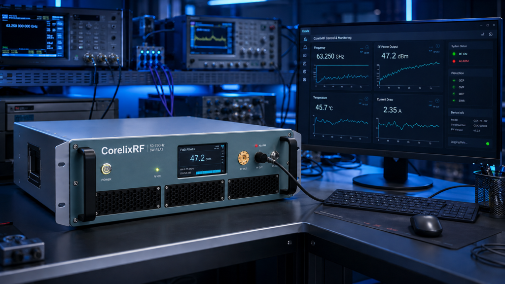
The source data lists forced-air cooling in a 19-inch 3U format. In practice, the waveguide path can limit where the unit can sit. Leave room for intake and exhaust, avoid hard bends that block service access, and make sure operators can inspect the WR15 interfaces without disassembling half the rack.
Field Note: Measurements Need Context
During commissioning, log frequency, source setting, gain state, measured output, current, temperature, and alarm status. The log should also describe where power is measured. If output is recorded after a coupler or fixture, the record should say so. CorelixRF RF testing and validation content is a useful internal reference for this kind of chain-level evidence.
Field Note: Shared Labs Need Operating Boundaries
If several teams will use the amplifier, create a short operating boundary document. List approved frequency range, approved WR15 path, maximum source settings, gain-control recipe, load-verification practice, and alarm response. This protects the amplifier and reduces support time when a later user changes the setup.
Field Note: Know When to Escalate
A standard unit may fit if 50-75 GHz, 8 W, WR15 interfaces, 3U packaging, forced-air cooling, and monitoring align with the bench. Escalate to custom RF development when the system needs a different interface, coordinated source hardware, special enclosure, nonstandard control behavior, or a project-specific test package.
Field Handoff Checklist
Before the amplifier is handed to routine users, confirm the reference plane, WR15 path, source limit, gain setting, airflow, monitoring method, load or antenna condition, and recovery procedure. If the amplifier is part of a larger high-frequency RF capability project, include the surrounding source and measurement hardware in the handoff notes.
Field Note: First-Day Setup Record
On the first day, photograph or document the WR15 path, record the source configuration, and save the initial measurement table. The record should identify who assembled the waveguide path and who approved the source limits. If a later test result changes, the team can compare against this baseline instead of rebuilding the setup from memory.
Field Note: Operator Training
Operators should know the approved connection sequence, safe source level, normal gain state, airflow requirement, and alarm response. Keep the instructions short enough to use at the bench. Long manuals are useful for reference, but a shared lab also needs a quick operating card that prevents avoidable handling and startup errors.
Field Note: Maintenance Trigger
Create a maintenance trigger when output readings drift, alarms become frequent, waveguide hardware is replaced, or the amplifier moves to a different rack. The trigger does not mean the amplifier is defective. It means the setup should be rechecked before the next formal data run.
Field Note: When the Setup Changes
Any change to source, waveguide, coupler, load, antenna, rack position, or control settings should create a new setup record. This is especially important when the amplifier supports more than one project. Without a new record, the team may compare data from two different RF paths as if they came from the same bench.
Field Note: What to Tell CorelixRF
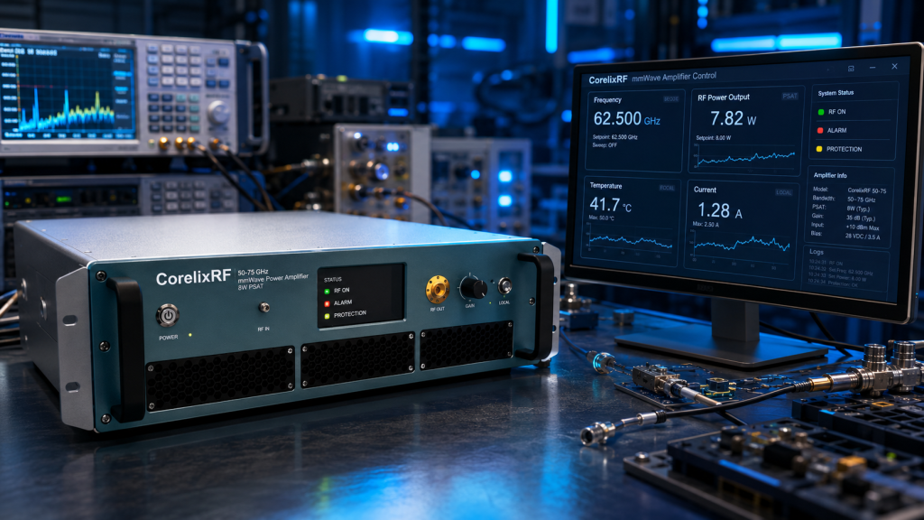
When requesting support, send the model, frequency points, reference plane, WR15 path, source level, gain state, load condition, current, temperature, alarm state, and photos or drawings of the setup where useful. That information shortens the path from problem report to useful engineering response.
FAQ
What frequency range is listed?
The source datasheet lists 50-75 GHz.
What output power is specified?
The datasheet lists 8 W rated output power.
What RF interface should be planned?
The source data lists WR15 input and WR15 output.
Why does field documentation matter?
Waveguide path, reference plane, handling practice, airflow, and measurement method can strongly affect repeatability.