
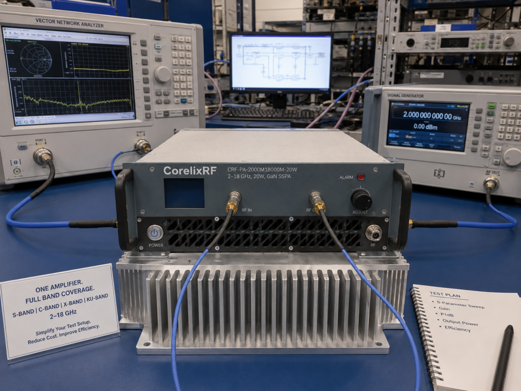
A 2-18 GHz broadband RF power amplifier is often selected when engineers need one compact RF platform to support multiple microwave test bands. Instead of changing narrowband amplifiers for every frequency segment, a wideband solid-state amplifier can simplify RF test benches, communication validation systems, EMC-related setups, and system-level integration work.
The CorelixRF CRF-PA-2000M18000M-20W is a practical example. It operates from 2 GHz to 18 GHz, provides 20 W rated RF output power, and is built on a GaN SSPA architecture. For engineers comparing amplifier options, the important question is not only whether the frequency and wattage look correct. Gain, gain flatness, input drive limit, VSWR protection, connector type, power supply, and cooling all affect whether the amplifier will work reliably inside a real RF system.
Start With Frequency Coverage and Output Power
The first selection point is continuous frequency coverage. A 2-18 GHz amplifier covers many common microwave test requirements across S, C, X, and Ku-band work. The CRF-PA-2000M18000M-20W is specified for 2 GHz to 18 GHz operation with 20 W rated output power. This makes it useful for test and measurement instrumentation, communication systems, RF interference system-level testing, and aerospace control validation.
When reviewing any RF power amplifier, confirm whether the rated output power applies across the full band or only at selected points. Ask for final test data under the intended operating conditions, especially if the system uses long-duration CW operation, high duty cycle waveforms, or load conditions that may create reflected power.
Review Gain, Gain Flatness, and Input Drive
The CRF-PA-2000M18000M-20W provides 43 dB minimum small-signal gain, with small-signal gain flatness specified at -5 dB to +5 dB. These values matter because a broadband test system must deliver predictable output power across a wide frequency span. If gain variation is ignored, a test setup can pass at one frequency and underperform at another.
The maximum input power is specified at 0 dBm. System integrators should verify the drive level from the signal generator, SDR, upconverter, or exciter before connecting the amplifier. Over-driving the input can cause compression, distortion, protection trips, or hardware risk. A clean RF chain should include proper level control before the broadband RF amplifier.
Check Connectors, Control, and Cooling Before Integration
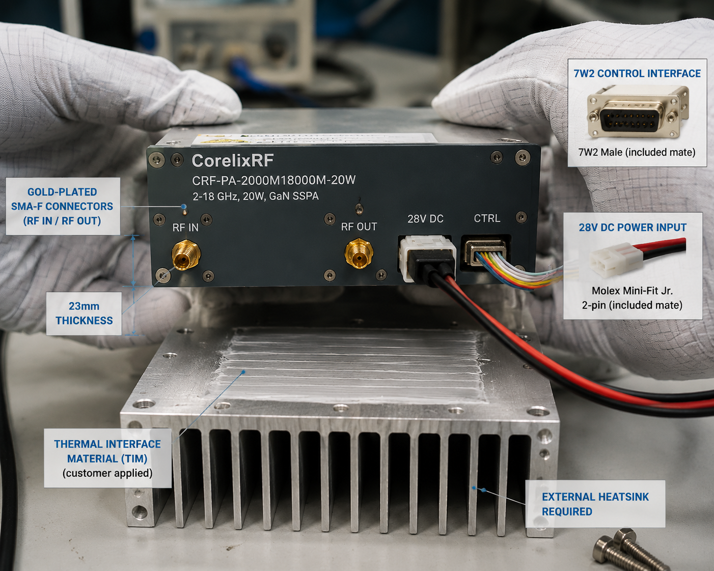
The amplifier uses SMA-F input and output connectors, a 7W2 rectangular control connector, and a 28 V DC supply. The mechanical form factor is 200 x 100 x 23 mm, with a listed weight of about 1 kg. This compact size can help when the amplifier needs to fit inside a custom test fixture or rack-mounted subsystem.
Cooling must be planned early. The source data specifies that an external heatsink is required. That means the amplifier should not be treated as a sealed standalone block. Thermal interface material, mounting pressure, heat spreader design, airflow, and ambient temperature all influence long-term reliability. For projects where thermal margin is uncertain, CorelixRF can review the mechanical and cooling plan before final configuration.
Protection Features Reduce Integration Risk
Broadband systems are exposed to changing loads, cables, antennas, test fixtures, and operator error. The CRF-PA-2000M18000M-20W includes real-time temperature monitoring, real-time current monitoring, alarm and fault protection, over-temperature protection, over-drive protection, over-voltage protection, and VSWR protection with alarm functions. Optional forward and reverse power monitoring can also be reviewed for project-specific builds.
These functions are especially important when the amplifier is used with antennas, switched RF paths, or external loads. VSWR events can happen quickly, and a good protection strategy helps reduce the chance of field failure. Engineers planning a custom RF amplifier should include expected load mismatch conditions in the RFQ.
What to Send for a Project Review
Before requesting a quotation, provide the frequency range, required output power, CW or pulsed operation, waveform type, duty cycle, input drive level, gain control needs, cooling method, mechanical limits, interface requirements, and environmental conditions. These details help determine whether a standard module is enough or whether a modified mechanical, thermal, or monitoring configuration is needed.
The 2-18 GHz 20 W GaN SSPA platform is a strong candidate when engineers need wide microwave coverage, compact size, and integrated monitoring. The best result comes from reviewing the amplifier as part of the full RF chain, not as an isolated wattage number.
FAQ
What is the focus keyword for this article?
The focus keyword is 2-18 GHz broadband RF power amplifier.
What is this amplifier used for?
It is used for RF test systems, communication validation, broadband microwave testing, RF interference system-level testing, and custom RF system integration.
Does the module need external cooling?
Yes. The source data notes that an external heatsink is required, so thermal design should be reviewed before installation.
Convert the amplifier article into a test-system RFQ
For a 2-18 GHz or wideband amplifier project, buyers usually need more than a headline power number. Ask our engineers to check frequency coverage, saturated and linear output power, gain flatness, harmonics, control interface, cooling limits, mismatch protection and required test curves before you lock the RFQ.
Recommended next step: send the target band, output power, duty cycle, load condition, control interface, cooling limit and required FAT documents. CorelixRF can map this 2-18 GHz broadband RF amplifier test systems requirement to a standard platform or a controlled customization path.