
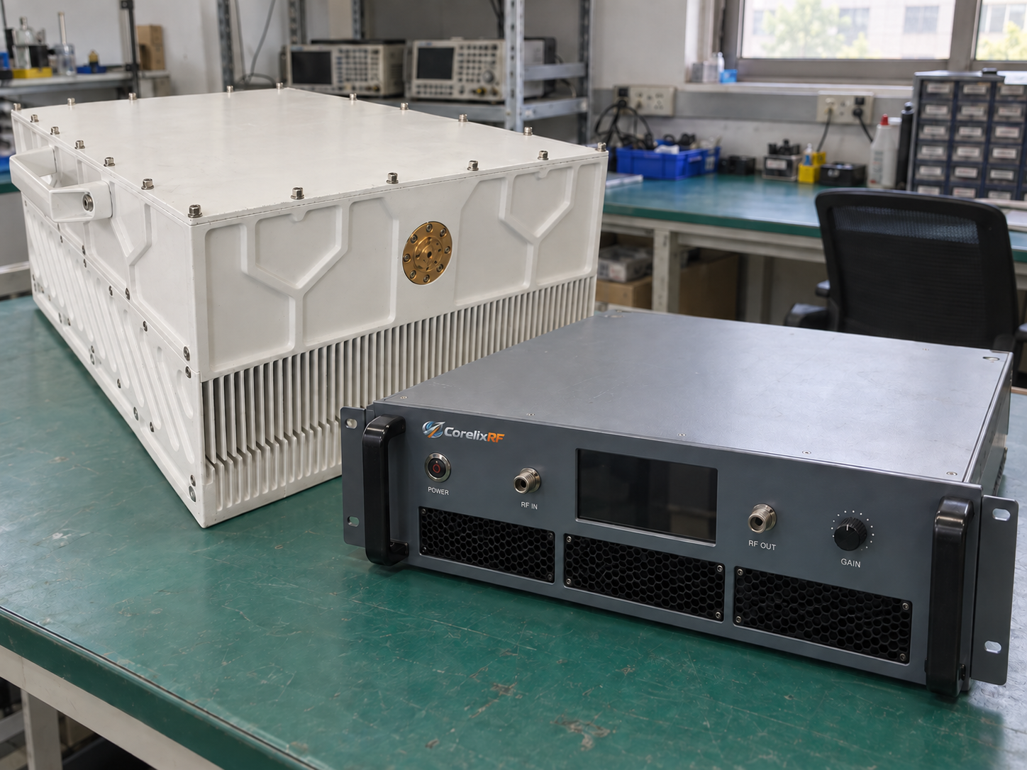
RF power amplifier classes describe how the output stage works. They help you weigh signal quality, power use, and heat. The best choice depends on your signal and the job the amplifier must do. Start with the required band, output power, and distortion limit. Then use measured data to check which design meets those needs.
A class name alone cannot tell you how much clean power a unit will deliver. For example, a Class AB unit may support different output levels for a single carrier and a wideband signal. Two units in the same class may also need different cooling. Compare them at the point where you plan to use them.
1. What Do RF Power Amplifier Classes Mean?
Conduction angle and bias
Conduction angle is the part of one RF cycle in which the device carries current. One full cycle is 360 degrees. If current flows for half that cycle, the conduction angle is 180 degrees.
Bias sets the device’s starting point before the RF signal arrives. Both bias and drive level affect when current flows. Classes A, AB, B, and C use this conduction behavior to describe a stage.
| Class | Ideal conduction angle | What happens in one RF cycle | What to check |
|---|---|---|---|
| A | 360° | The device conducts for the full cycle. | Clean output and heat at the required power. |
| AB | More than 180°, less than 360° | The device conducts for more than half the cycle. | Distortion and power use at the chosen output. |
| B | 180° | The device conducts for half the cycle. | How the full circuit controls distortion. |
| C | Less than 180° | Current flows for less than half the cycle. | Whether the tuned stage suits the signal. |
These ideal class definitions apply to a device or stage with a repeating drive signal. In real use, conduction can change as drive rises. Check the bias and drive that go with a class label.
Class, device type, and operating mode
GaN is a semiconductor material. LDMOS is a type of transistor. Neither name tells you the class of the whole unit. Ask for class data for the exact design if your project needs it.
CW and pulsed operating modes describe how RF power is delivered over time. State pulse width, pulse rate, and duty cycle in your RFQ. Conduction angle describes when current flows within one RF cycle. Give both the pulse timing and class if the design calls for them.
2. When Is Class A a Good Fit?
Clean output within the rated range
A Class A stage conducts for the full RF cycle within its intended range. The device does not cut off during that cycle, which can help keep distortion low. This can suit a driver stage or a test chain that needs clean gain.
Class A still has limits. Excess drive can push it into compression, where output no longer rises in proportion to input. The band, load, device, and heat also affect the result. Therefore, request distortion data at the power you need.
Name the test signal when you compare results. You might need a single carrier, a two-tone test, or a modulated waveform. Each places its own demands on the stage. Good data from one test does not prove the same result with a new signal.
Idle current and cooling
Quiescent current flows with no RF drive. State the bias and enable setting when you quote it. In Class A, this idle current can use a lot of power even at low RF output. Check both the idle state and the full run.
For example, a stage left enabled for hours needs cooling during those idle periods. A system that disables unused stages has a different heat profile. Use measured input and output power to build the heat budget.
Review the rack cooling requirements for the proposed mounting, air temperature, and airflow. Before you approve a heatsink or cabinet, check:
- Output power and distortion across the required band.
- Power drawn while idle and while transmitting.
- Cooling needs during the longest planned run.
3. How Do Class AB and Class B Compare?
Class B and the complete RF circuit
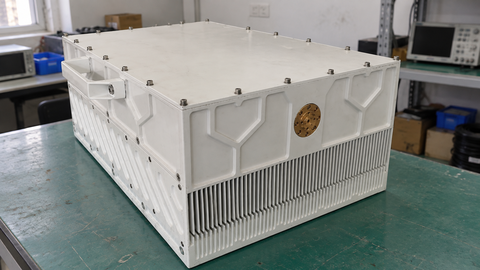
A Class B device conducts for half the RF cycle. This can reduce standing power use compared with Class A. However, the full circuit determines how those current pulses become useful RF output.
In a push-pull stage, each device handles part of the cycle. Distortion can occur as one hands over to the other. Tuned RF stages also use networks to select the wanted part of the spectrum. Thus, an audio crossover example cannot explain every RF circuit.
Check measured output from the full stage. Ask which band, drive level, signal, and load produced each result. The conduction angle alone cannot prove that the signal is clean enough for your task.
Class AB at the required output
Class AB bias lets current flow for more than half a cycle at the intended drive level. It balances idle power use with linearity. Yet two Class AB units can still differ in gain, heat, and distortion limits.
For a modulated signal, use an EVM versus output power curve to find the output that meets your signal-quality limit. Keep the waveform and test settings with the curve. Also include adjacent-channel limits when your system needs them.
If quoted efficiency applies near saturation, ask for data at the output you need. A signal with large peaks may need power backoff. Ask how much average power the unit can supply while keeping those peaks clean. The lower output point can change both efficiency and heat.
Treat bias as part of the tested design. A change may affect gain, current, distortion, or stability. Follow the design owner’s instructions and test the revised setup before using it.
4. Where Can Class C Fit?
Tuned output and the signal envelope
Class C conducts for less than half an RF cycle. Its device current contains strong harmonics. A tuned output network selects the desired frequency component and presents the required load to the device.
This can suit tasks that permit nonlinear gain. For example, a narrowband signal with a constant envelope has different needs from one whose amplitude carries data. Specify the signal bandwidth, envelope, and allowed distortion before choosing the class.
If the signal’s amplitude changes, check envelope distortion through the full transmitter. A band and wattage figure alone cannot prove that the stage will keep your signal intact.
Band, load, and pulse limits
A tuned stage needs test data across its stated band. Matching and harmonic loads can change the result away from the design frequency. Ask how measured output power and the output spectrum vary across your band and load conditions.
Pulse use adds more checks. State rise and fall times, pulse flatness, and average heat load. Check these for every class. Choose a unit when its measured output and signal quality meet your limits under the stated conditions.
5. What Changes with Classes D, E, and F?
Switching and waveform control
Classes D, E, and F use switching or shape voltage and current waveforms. A conduction-angle table alone cannot explain how these circuits work.
A Class D RF stage uses switching devices and an output network suited to the design. Switching losses, stray circuit effects, filtering, and frequency all affect real performance.
Class E aims to cut switching loss. In an ideal form, the output network brings switch voltage near zero at turn-on. Real devices and networks still have losses and limits.
Class F uses selected harmonic impedances to shape waveforms. Check the bias, drive, and harmonic loads. Also check output at the wanted frequency. A class name cannot supply those circuit details.
Check the useful bandwidth
An efficiency figure belongs to one circuit and test point. Device capacitance, switching speed, and network loss can change the result. A network tuned for one point may not work the same way across the band.
For broadband amplifier selection, compare clean output across all required frequencies. Then check the supply, cooling, and interfaces. Ask for:
- Measured power and signal quality across the band.
- The waveform used for each efficiency result.
- The load, supply, and cooling used in each test.
Keep ideal efficiency figures marked as theory. Use measured results to select a module or a complete unit.
6. Which Specifications Matter Beyond Class?
Define the output power first
When comparing RF power amplifier classes, use the same band, waveform, supply, and heat conditions. Also check what each power figure means. Saturated output, output at a stated compression point, peak envelope power, and average modulated power describe different limits.
Our guide to RF amplifier specification definitions helps you compare those terms. For backoff, name the reference point too. Power below saturation cannot be compared directly with power below a different compression reference.
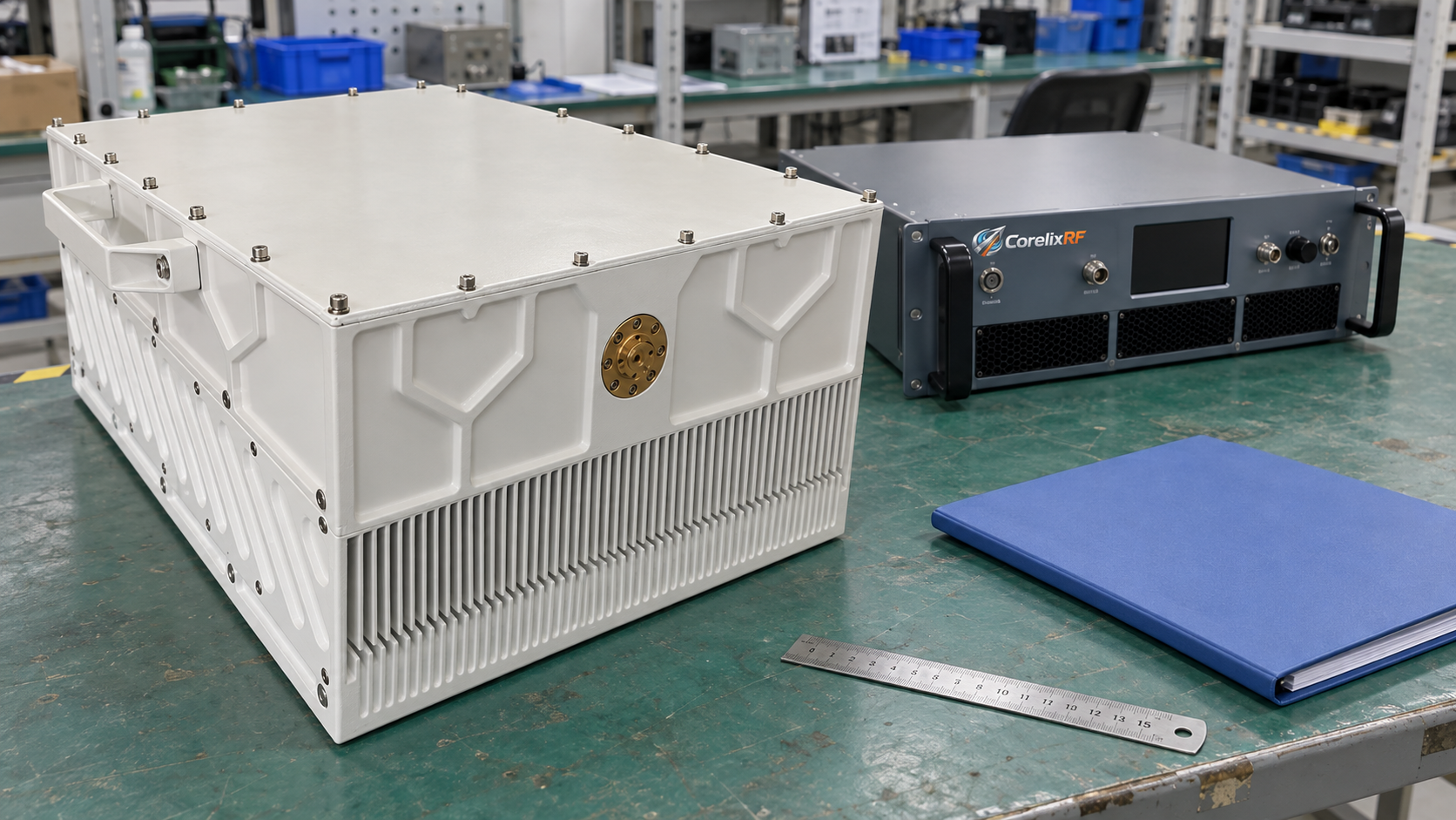
The CRF-PA-47G51.4G-400W is part of our 47–51.4 GHz millimeter-wave amplifier range. Its datasheet lists saturated output and rated linear output separately. The 400 W model label does not define clean output for your waveform. Compare both ratings with your signal and distortion limits.
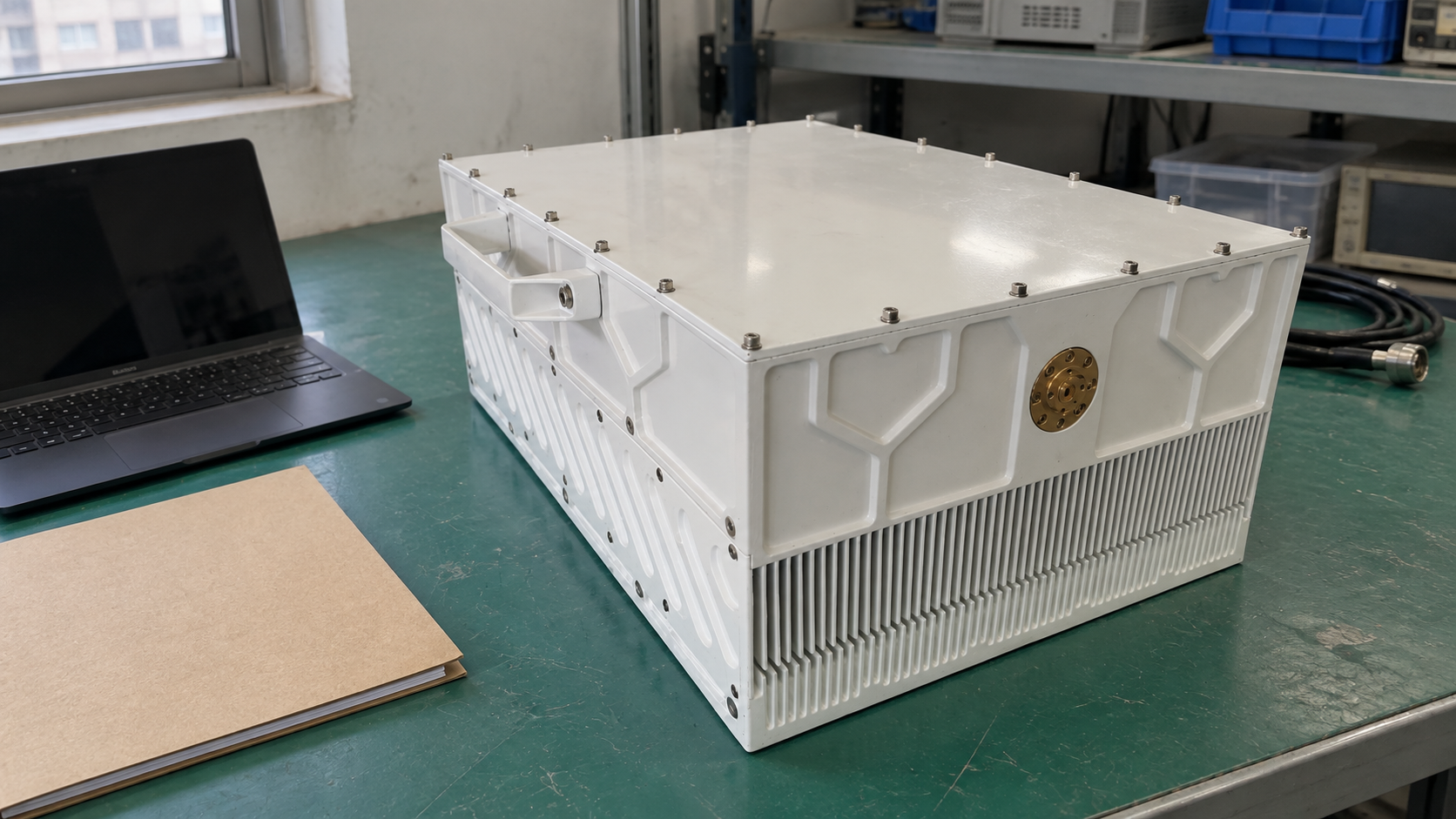
For modulated use, state average power, bandwidth, and crest factor. Add EVM or adjacent-channel limits where needed. Record any linearization used in the test. Was the unit cold, or had it warmed up? Give the test temperature and run time with the results.
Use the same efficiency boundary
Efficiency tells you how much input power becomes RF output, but the chosen boundary changes the calculation. Use the same boundary for both candidates.
| Measure | Calculation | What to record |
|---|---|---|
| Drain efficiency | RF output divided by drain DC input. | Drain supply and the output power definition. |
| Power-added efficiency, or PAE | RF output minus RF input, divided by stage DC input. | Supply rails, RF reference planes, and waveform. |
| System RF efficiency | RF output divided by total electrical input. | Whether supply losses, cooling, and controls are included. |
Multiply each ratio by 100 to get a percentage. For pulses or modulated signals, use matching power definitions and averaging times.
To estimate heat in a steady state, first set the boundary for your calculation. Add input from the power supply and absorbed RF input. Then subtract net RF output. Include other energy paths if they matter. An efficiency figure alone cannot size the cooling system. Ask how much power the unit draws at your output and during long idle periods.
7. How Do You Choose a CorelixRF Amplifier?
Build the RFQ around your signal
Put your signal and site needs in an RF amplifier RFQ before you choose a class. If your design needs one class, state which one and why. Otherwise, compare units against the same measured limits.
| Requirement | Include in the RFQ | Request as evidence |
|---|---|---|
| Band | Frequency range and signal bandwidth. | Results across the required band. |
| Output | Power definition, target, and reference plane. | Output data under those conditions. |
| Signal quality | Waveform and distortion limits. | Relevant curves or test reports. |
| Mode | CW or pulse settings and run time. | Data for the stated mode. |
| Supply and heat | Available power, airflow, and temperature. | Power draw and cooling needs. |
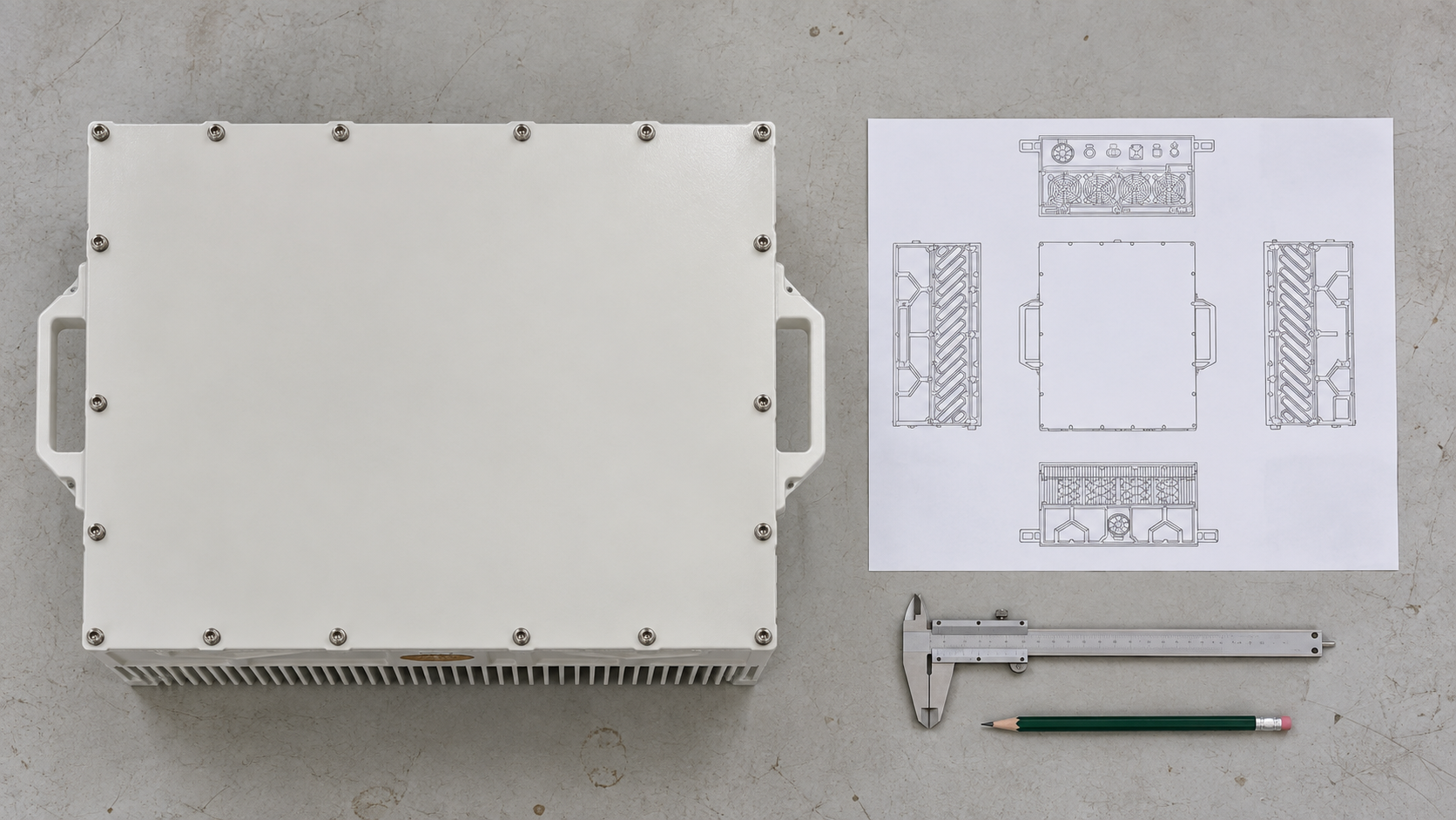
| Installation | RF ports, controls, size, and load. | Drawings and details of the quoted build. |
Mark any missing value as an open question. Resolve it before using the value to size a supply, heatsink, or rack.
Compare the exact model and build
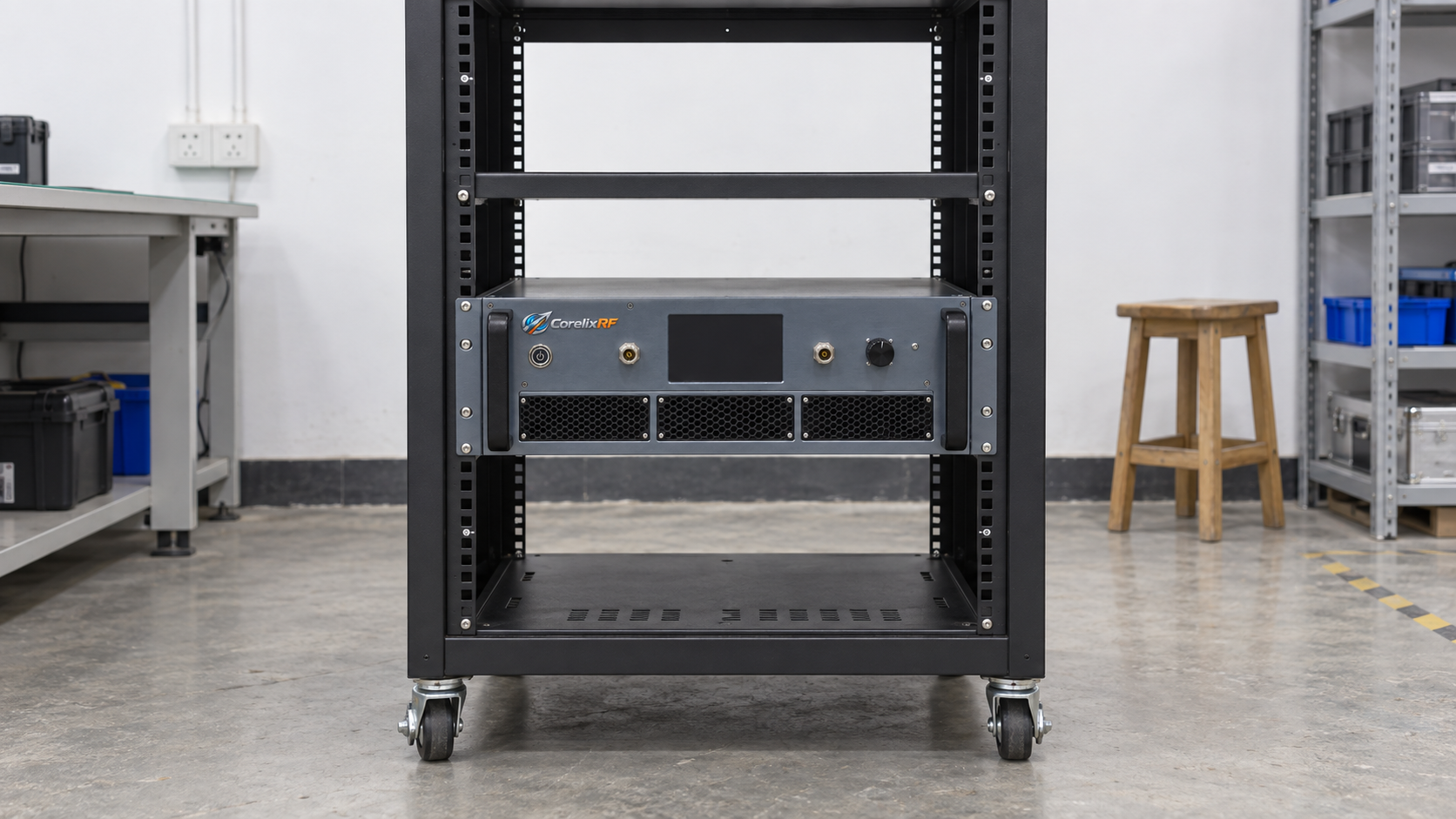
Our CRF-PA-6000M18000M-50W is a 6–18 GHz RF power amplifier. Its datasheet lists at least 50 W output and at least 47 dB small-signal gain. This version uses 220 V AC power and a 19-inch, 3U rack enclosure.
For a modulated signal, request power and distortion data with your waveform and cooling setup. The wattage of these products does not prove their class. Nor does the band or product group. Confirm class for the exact build when it affects the choice.
Next, compare datasheet versions and test conditions. Ask which results are typical and which limits are guaranteed. Check which reports will ship with the unit. Resolve any differences in the builds before you compare the quotes.
Frequently asked questions
Is Class AB always the best choice?
No. It can offer a useful balance of linearity and power use, but fit depends on your band and signal. Compare measured distortion, output, and heat at the point where you will use the unit.
Does GaN always mean Class AB?
No. GaN identifies a device technology. Class depends on the circuit, bias, and drive. Ask for class data for the exact model and build.
Does pulsed operation mean Class C?
No. Pulses describe RF delivery over time. Conduction class describes device behavior within an RF cycle. State pulse timing and power needs as separate requirements.
Does higher ideal efficiency mean less cooling?
Not by itself. Cooling depends on actual heat and the way you install the unit. Use measured input and RF output, duty cycle, and thermal limits to plan the cooling.
Can I change class by adjusting bias?
Bias affects how the stage works, but a change needs a tested design. Follow the design owner’s instructions. Check current, distortion, stability, and heat before using new settings.
Send your requirement sheet to our engineering team for a model and configuration review. Include your waveform, operating conditions, required reports, and any mandatory class requirement.