
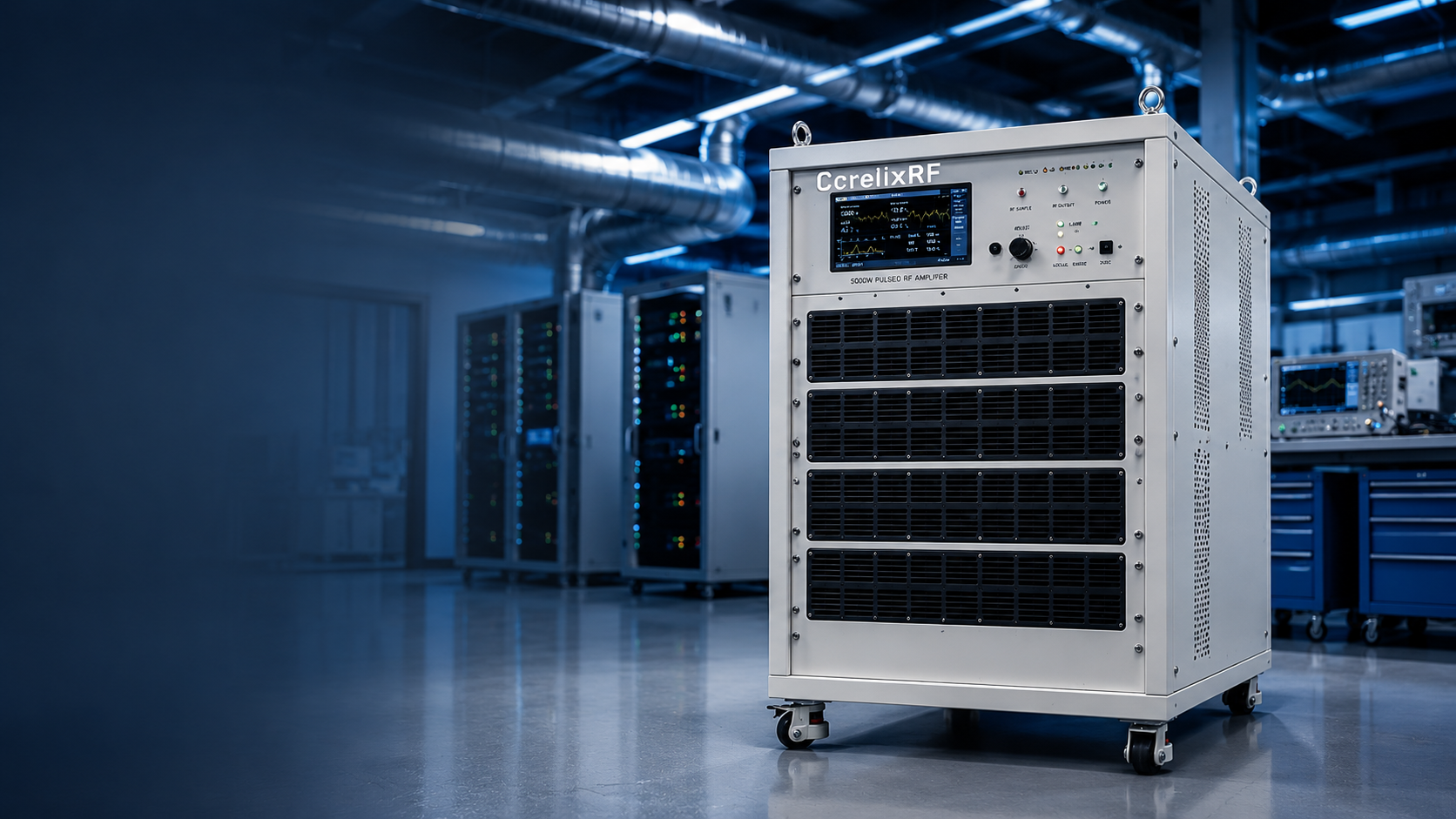
This article is written as a facility-readiness audit for teams preparing to quote, install, and accept a high-power pulsed RF system. The CorelixRF CRF-PA-2000M4000M-5000W local datasheet lists 2 GHz to 4 GHz frequency coverage, 5000 W pulsed RF output power, 1-50 us pulse width, 5% duty cycle, 60 dB minimum small-signal gain, GaN pulsed SSPA architecture, N-Female input, 7/16-F output, forced-air cabinet configuration, real-time temperature and current diagnostics, and alarm protection.
Audit Objective
The objective is not to prove every final system outcome before purchase. It is to confirm that the facility can support a pulsed RF amplifier of this power class without improvising around drive control, cabinet placement, load rating, cooling, interlocks, or measurement reference plane. A 2-4 GHz 5000W amplifier should be reviewed as a facility asset, not as a bench accessory.
Gate 1: RF Chain Definition
Before the RFQ is sent, the project team should document the source, attenuators, driver stages, couplers, output load, switching, and measurement equipment. Include expected source drive, pulse timing, reference plane, and whether the system will run fixed-frequency bursts or swept-frequency validation. The datasheet’s 60 dB minimum gain means small source-level changes can produce large output-level changes, so the drive plan needs written limits.
Gate 2: Pulse Profile and Duty Condition
The local specification identifies 1-50 us pulse width and 5% duty cycle. That information should appear in the acceptance file together with PRF, expected test duration, peak power, average power, and any blanking or receiver-protection timing. A short checkout pulse is different from a repeated qualification profile. If the program needs a waveform outside the listed timing envelope, treat that as an engineering review item rather than a sales assumption.
Gate 3: Output Hardware
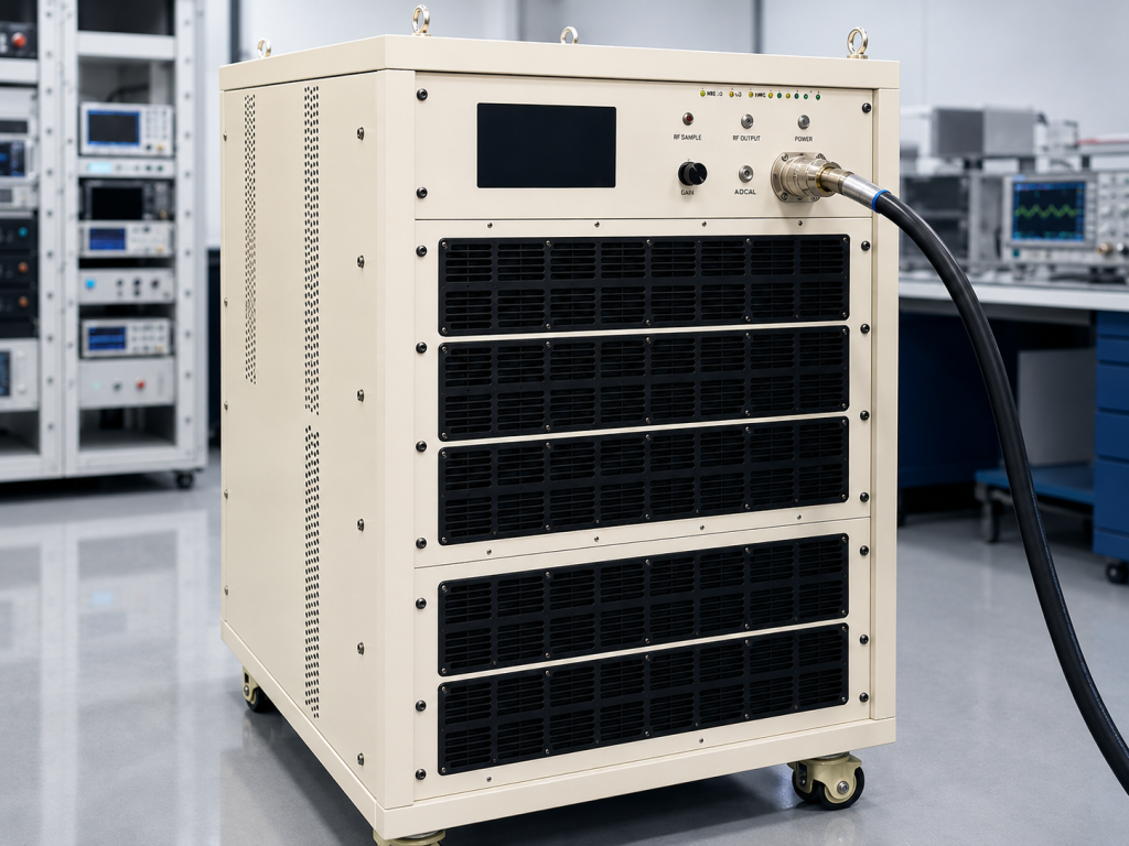
The output path should be rated and inspected before RF is enabled. The 7/16-F output connector, coupler, cable, load, and any antenna path need frequency and power margin. Label the approved output chain and keep spare adapters under control. High-power solid state power amplifier systems often fail operationally because the passive hardware was treated as secondary.
Gate 4: Facility Cooling
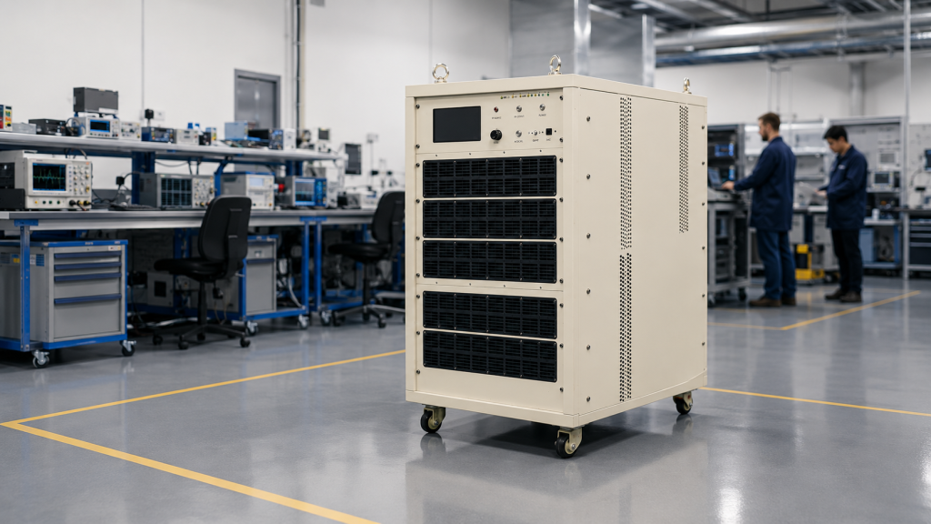
Forced-air cabinet cooling is simpler than a water loop, but it still needs facility planning. Confirm intake clearance, exhaust clearance, room heat rejection, rack or cabinet spacing, filter access, and service clearance. During acceptance, log frequency, pulse condition, output power, current, temperature, and alarm state. Those records become the baseline for later troubleshooting.
Gate 5: Protection and Control
The datasheet references diagnostics, alarms, and project-ready control interfaces. Define what the controller does when an alarm appears: remove drive, disable RF, log the condition, notify the operator, and require a reset sequence. For a custom RF amplifier project, ask CorelixRF how alarm states can be mapped into the facility control system.
Pass/Fail Checklist
The facility is ready when source limits are defined, pulse timing is documented, the output path is rated, cabinet airflow is reserved, operator access is safe, alarms are visible, and acceptance data has a named reference plane. If any item is unclear, the RFQ should request clarification instead of hiding uncertainty until installation.
Evidence to Attach to the Readiness Record
The readiness file should include a block diagram, power budget, pulse table, cabinet layout, output-path rating list, and operating limits. It should also record who owns source programming, who verifies the output load, and who can reset the amplifier after an alarm. These are mundane details, but they prevent a high-power pulsed system from being treated as a simple lab source after handoff.
For search intent, this style targets engineers looking for a high power pulsed RF amplifier, 2-4 GHz RF amplifier, 5000W RF amplifier, or GaN SSPA for pulsed RF testing. The useful content is the readiness sequence: source control, pulse definition, output hardware, facility cooling, diagnostics, and protection. That is more valuable than a generic paragraph saying the amplifier is powerful.
What the Contact Request Should Say
When contacting CorelixRF, include the frequency range, expected pulse width, duty cycle, PRF, source drive range, target output reference plane, cooling environment, control interface, cabinet constraints, load condition, and required acceptance data. If the project has safety interlocks, receiver blanking, or external facility controls, list them in the first message. The better the first request, the faster the engineering review can separate standard configuration from project-specific work.
The owner list should be explicit. Name the person or team responsible for source programming, RF load readiness, cabinet airflow, safety interlock review, and acceptance data. High-power pulsed projects become fragile when ownership is implied rather than written. A short responsibility table keeps the facility audit practical and makes the handoff easier after installation.
FAQ
What is the primary search phrase for this article?
The primary search phrase is 2-4 GHz pulsed RF amplifier.
What output power does the local datasheet list?
It lists 5000 W pulsed RF output power.
Why does facility readiness matter for this amplifier?
The 5000 W pulsed power class affects source control, load rating, cabinet placement, cooling, alarms, and operator procedure.
Should the article claim stock or certification status?
No. The article should only use the local product specifications and avoid unsupported stock, certification, or customer-use claims.