
Use this article as a bench standard operating procedure for the CorelixRF CRF-PA-10M50G-1W. The local datasheet lists 10 MHz to 50 GHz coverage, 1 W-class rated output power, GaN SSPA architecture, 29 dB minimum gain from 10 MHz to 20 GHz, 20 dB minimum gain from 20 GHz to 50 GHz, 2.4 mm female RF input and output, forced-air mini chassis cooling, RS485/LAN project-ready control interfaces, temperature/current diagnostics, and alarm protection.
SOP Scope
This SOP is for engineers setting up an ultra-wideband RF amplifier bench where the amplifier may be used as a driver, broadband test source stage, receiver-stress tool, or RF path validation block. It does not claim the final system will meet any specific EMC, communication, or aerospace requirement. It gives a repeatable way to set up and document the bench.
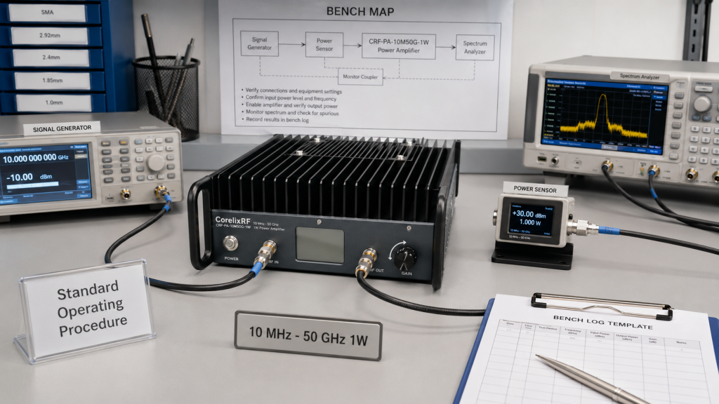
Step 1: Define the Bench Map
Sketch the signal generator, switches, attenuators, amplifier, couplers, sensors, loads, and measurement instruments. Write down the reference plane for output power. A 10 MHz to 50 GHz amplifier spans too much frequency range for casual cable choices. Identify which cable and adapter set is approved for low-frequency work and which set is approved near the upper microwave and mmWave region.
Step 2: Split the Frequency Plan
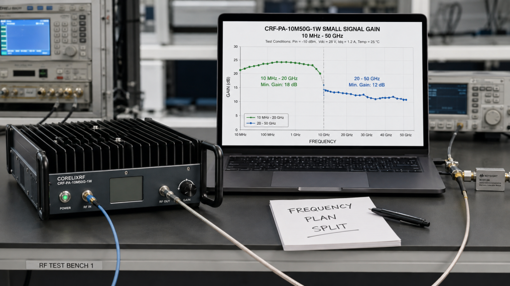
The datasheet separates gain into two regions: 10 MHz-20 GHz and 20-50 GHz. Treat those as two setup regions. For a broadband RF power amplifier bench, choose representative test points in both regions and do not rely on one mid-band check. Record the expected source level and measured output at each point.
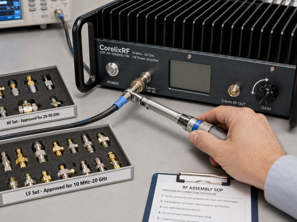
Step 3: Handle 2.4 mm Connectors Correctly
The listed 2.4 mm female input and output are suitable for high-frequency work, but they require disciplined handling. Inspect mating surfaces, avoid unnecessary adapters, use appropriate torque practice, and keep cable strain away from the amplifier ports. If several teams share the amplifier, list approved cables and adapters in the bench procedure.
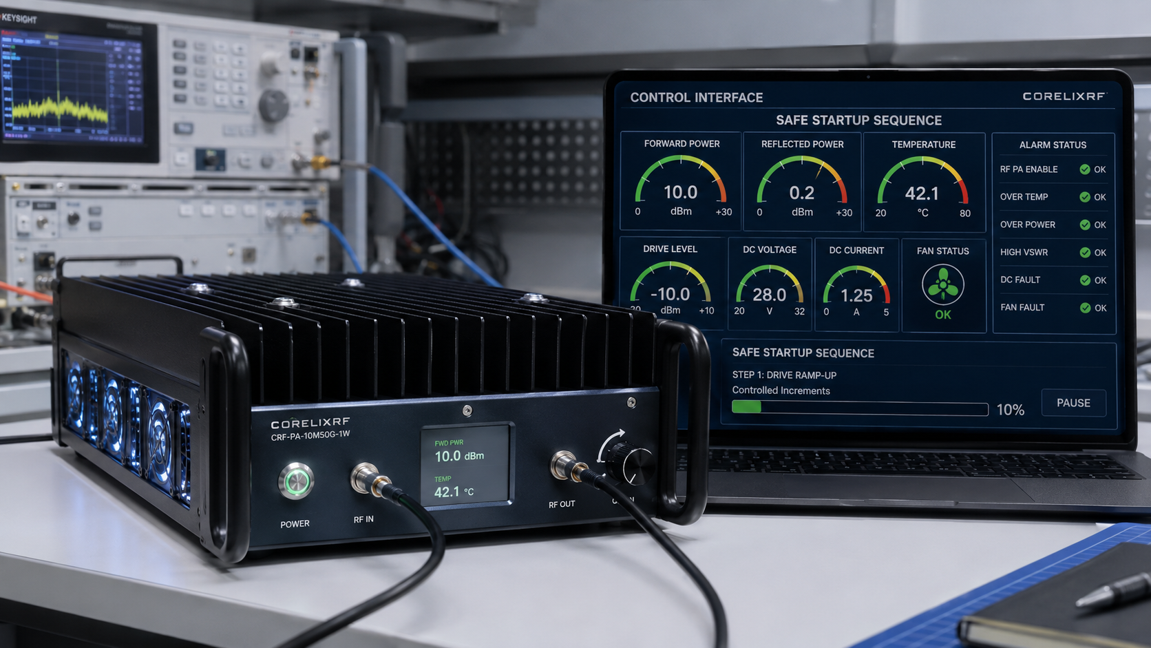
Step 4: Establish Safe Startup
Begin with the source disabled or set to a low level, verify attenuation, connect the rated load or instrument path, confirm cooling airflow, and enable monitoring. Increase drive in controlled increments. Save the source level, output level, current, temperature, and alarm state. If the setup is automated, the software should include a maximum drive limit.
Step 5: Record What Changed
Ultra-wideband benches become unreliable when users swap cables or reference planes without documentation. Every test record should identify the cable set, adapter set, frequency points, source level, gain state, and output measurement instrument. This is the difference between a useful acceptance baseline and a one-time reading that cannot be reproduced.
When to Ask for Engineering Review
Ask CorelixRF for a custom RF amplifier review when the project needs unusual control, special packaging, different cooling, or a defined interface to another instrument. If the application is closer to immunity or interference testing, also compare the EMC RF amplifier category before narrowing the RFQ.
Bench Log Template
A repeatable log should include date, operator, source model, cable set, adapter set, frequency points, source level, gain state, output level, current, temperature, alarm state, and the measurement instrument used. Add one line for any physical change to the setup. If a 2.4 mm cable is replaced, if a coupler is reversed, or if the output measurement plane moves, the log should say so.
For long-tail search intent, this article is aimed at engineers searching for ultra-wideband RF amplifier setup, 10 MHz to 50 GHz amplifier, SDR RF amplifier driver, microwave amplifier bench setup, and broadband amplifier test chain. Those readers usually want practical setup boundaries, not broad claims. The SOP format answers that need by telling them how to prepare the bench.
Operator Notes
Operators should not normalize alarms or unexplained output shifts. If measured output changes after a cable or adapter swap, return to a known low-power condition, inspect the path, and repeat the baseline points. The CRF-PA-10M50G-1W covers an unusually wide range, so the passive path often explains measurement differences. Documenting the path is part of using the amplifier correctly.
Schedule a short repeatability check after the first successful setup. Use the same frequency points, cable set, and measurement reference plane, then compare readings to the first log. If the difference is larger than expected, investigate the passive path before changing amplifier assumptions. This SOP-style habit is especially useful when the unit supports both low-frequency and high-frequency work.
Keep this repeatability check lightweight but mandatory. It should take minutes, not hours, and it gives the lab confidence that the setup can be rebuilt after routine handling.
FAQ
What is the primary search phrase for this article?
The primary search phrase is 10 MHz-50 GHz ultra-wideband RF amplifier.
What connectors does the local datasheet list?
It lists 2.4 mm female RF input and output connectors.
Why should the frequency plan be split?
The datasheet lists different minimum gain figures for 10 MHz-20 GHz and 20-50 GHz, so both regions should be represented in setup checks.
Does this guide include visual media?
No. The article is text-only and does not include visual media instructions.