
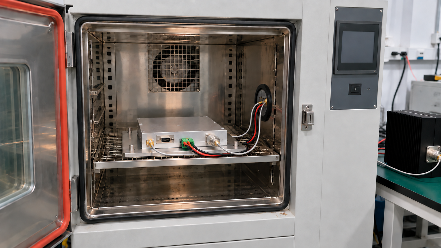
RF amplifier environmental testing should match the place where the unit will work. A power amplifier may pass a room-temperature bench test and still fail inside a hot cabinet or a moving vehicle. The test plan must match the mount, cooling path, RF load, signal mode, and local weather. This guide turns broad requests such as “high-temperature resistant” into checks that a buyer and supplier can review before the quote and final approval.
Contents
- Where will the amplifier work?
- Which tests match that site?
- Should the amplifier run during each test?
- What should you check before, during, and after a test?
- Does the report cover the unit you will receive?
- What belongs in the RFQ and approval plan?
Quick review
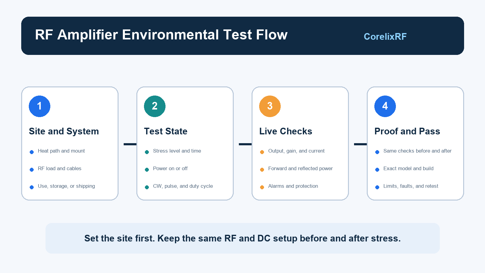
Start with the site. Mark where the unit will sit. Show the heat path, mount, RF load, cables, and power feed. Then choose each test for a known risk. State if the unit is on or off. Use the same setup before and after the stress. Log gain, output, current, alarms, and the protection state. Link each result to the exact model and build. Put the pass limits in the RFQ before testing starts.
Simple example
Take a rack unit in a van. First, mark the mount and air path. Run the unit at its set power. Log heat, gain, output, and alarms while the road test runs. Stop if a set limit is crossed. After the test, use the same cables and load to run the checks again. A pass means the data stay within the limits in the test plan. The report should name the unit, date, setup, and result.
1. Where Will the RF Amplifier Work?
Map the real setup before you name a test. Outdoor air temperature is not the same as the temperature beside a baseplate in a closed cabinet. A vehicle may have a vibration limit, but that limit does not show where the amplifier sits or how the bracket passes movement to the RF ports.
Unit State and Heat Path
Separate three states:
- Operation: The unit sends RF all the time, in short bursts, during set time slots, or on another known duty cycle.
- Storage: The power is off while the unit waits in a store room, vehicle, shelter, or field case.
- Transport: The packed unit faces handling, road movement, shock, or a drop.
As a result, each state answers a different question. A storage test followed by a restart shows that the unit can run again. It does not show that gain, output, current, or protection stayed within limits during the test.
Next, check the air and heat path near the unit. Record the air temperature at the inlet. Add case or baseplate temperature when it affects cooling. Note air flow, mount direction, and how heat leaves the unit. For a vehicle, show the bracket and the main source of vibration. Also state if the RF output stays on while the vehicle moves.
Add humidity, water, height, dust, or salt only when the site may expose the unit to them. The system may block some of these risks. For example, a sealed cabinet may keep dust and salt away from an amplifier module.
The unit format also sets the test boundary. A module relies on its host for power, cooling, control, and support. A rack unit brings more of those parts with it. Our module-versus-rackmount selection guide helps buyers mark which parts belong to the amplifier and which belong to the host system.
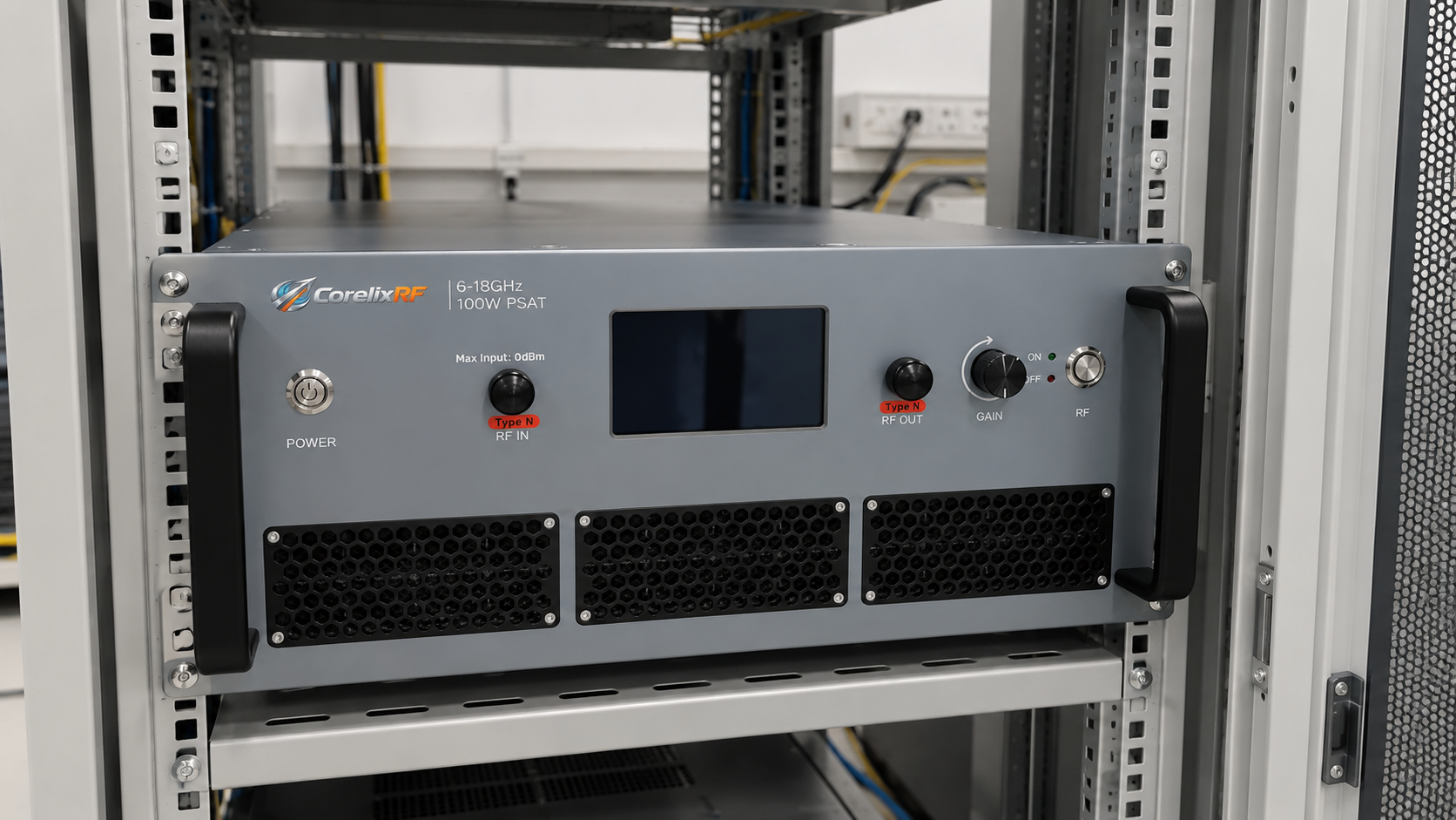
Start with the setup, then choose the test. Draw the unit, heat path, RF load, cables, power source, and test points. Mark any missing facts for review. Do not guess them.
2. Which Environmental Tests Match the Site?
A long test list can look complete and still miss the real risk. Each test should answer one clear question. State the stress, the unit state, what you will measure, and the result that counts as a pass.
Heat, Cold, Humidity, and Water
A heat or cold test may hold one temperature, move between two levels, or change fast. Each profile puts a different load on parts, joints, seals, and the cooling path. Therefore, write the rate, hold time, number of cycles, and unit state.
Humidity tests add moisture. Water that forms on a cold surface needs its own rules. State if power must stay off, when the unit may start, and how long it must dry. Running RF while water is present may test a very different state from an unpowered soak.
Movement, Shock, and Shipping
For example, vibration can find loose screws, moving connectors, weak joints, fan faults, or wires that cut in and out. Shock covers a short, hard event. A shipping test may focus on the box and packing instead of the installed unit.
For these tests, state the mount direction, fixture, axes, level, time, and unit state. A soft fixture and a stiff bracket do not pass the same movement to the unit.
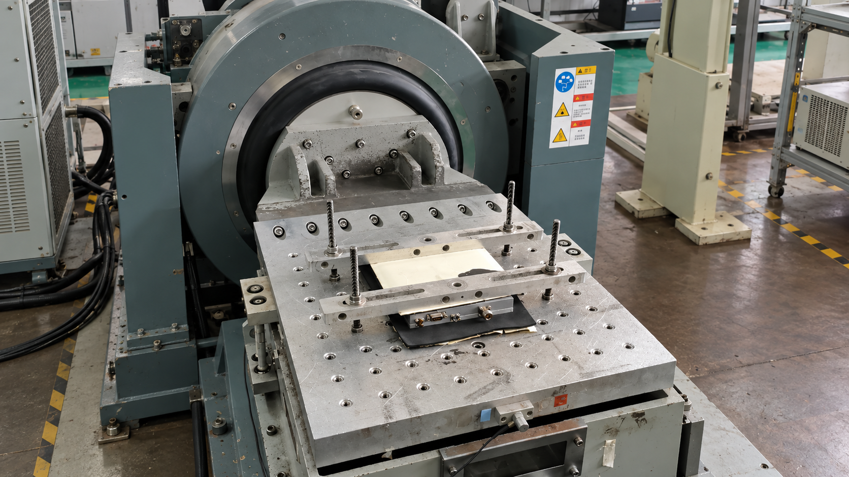
Choose tests from the site and the system boundary. Use the table below as a start, then set the exact level and pass rule for the project.
| Site or event | Test to review | Details to set | Useful record |
|---|---|---|---|
| Outdoor cabinet | Heat, cold, cycles, humidity, or water | Unit state, cabinet heat, cooling, and time | Test profile, RF/DC log, alarms, and restart |
| Vehicle or mobile mount | Vibration, shock, and heat change | Bracket, fixture, axes, and unit state | Setup photos, time log, and before/after checks |
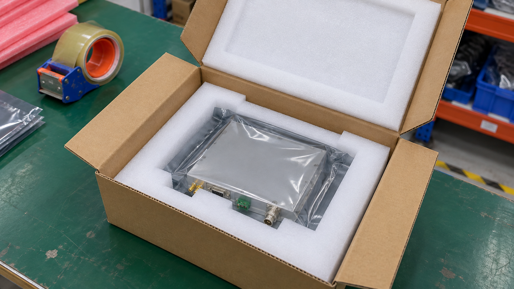
| Long trip | Packed vibration, shock, or drop | Box, packing, direction, and sample build | Packing record, inspection, and powered retest |
| High site | Low pressure and cooling review | Height or pressure, load, cooling, and output | Heat, output, current, and protection state |
| Coast or wet site | Humidity, salt, seals, and material review | Exposed parts, cabinet edge, and RF ports | Inspection and any needed function check |
Give every test a job. Remove a test that does not match the site. For each test you keep, name the fault or change that it should find.
3. Should the Amplifier Run During Each Test?
In practice, powered and unpowered tests answer different questions. An unpowered test may support storage, shipping, or proof that parts survive a stated stress. A restart after the test shows that the unit can run again. It gives no RF data from the time when the stress was present.
Next, a powered test needs one clear RF state. Record these items together:
- input drive and test frequency or sweep;
- output target, CW or pulse mode, pulse width, duty cycle, and run time;
- supply, load, cooling, control state, test order, and warm-up rule.
Without this record, two labs can use the same heat profile and still run two different tests.
Drive also needs care during startup and hot work. A level that gives normal output at one point may push another point near compression. The RF amplifier input-drive guide shows how gain, source level, and output target fit into a safe startup plan.
Also, the load belongs in the record. Cables, switches, antennas, and test gear can change loss and mismatch over frequency. Protection may cut power, turn the unit off, or call for a reset. A “VSWR protected” label does not tell you which result to expect. Our reflected-power protection guide lists the load, time, power, and reset details to check.
Use a mount and cooling path that match the final setup where they can affect the result. A lab heat sink may cool the unit far better than the real system. A heavy test plate may also hide a weak mount.
State the unit mode on every test sheet. Add two fields: “amplifier power state” and “RF test state.” These fields stop an unpowered survival test from being sold as powered RF proof.
4. What Should You Check Before, During, and After a Test?
First, build a baseline. Record the full model, hardware build, control or firmware build, serial number, and setup photos. Then measure the RF and DC items that matter at known frequencies and test points. These may include output, gain, current, forward and reflected power, alarms, and protection state.
During the test, log enough data to find a short fault. A reading at the start and end can miss a brief output drop, current jump, loose RF port, or trip. Match each fault with the heat, motion, supply, drive, load, and control state at that time. If protection acts, log the cause, output response, alarm, reset step, and recovery.
CW and modulated signals do not create the same drive, heat, or test load. Use the signal mode that fits the pass rule.
Keep the before and after checks the same:
- use the same frequencies, test points, and cable correction;
- use the same supply, drive, load, cooling, and control state;
- repeat the same RF, DC, alarm, and protection checks.
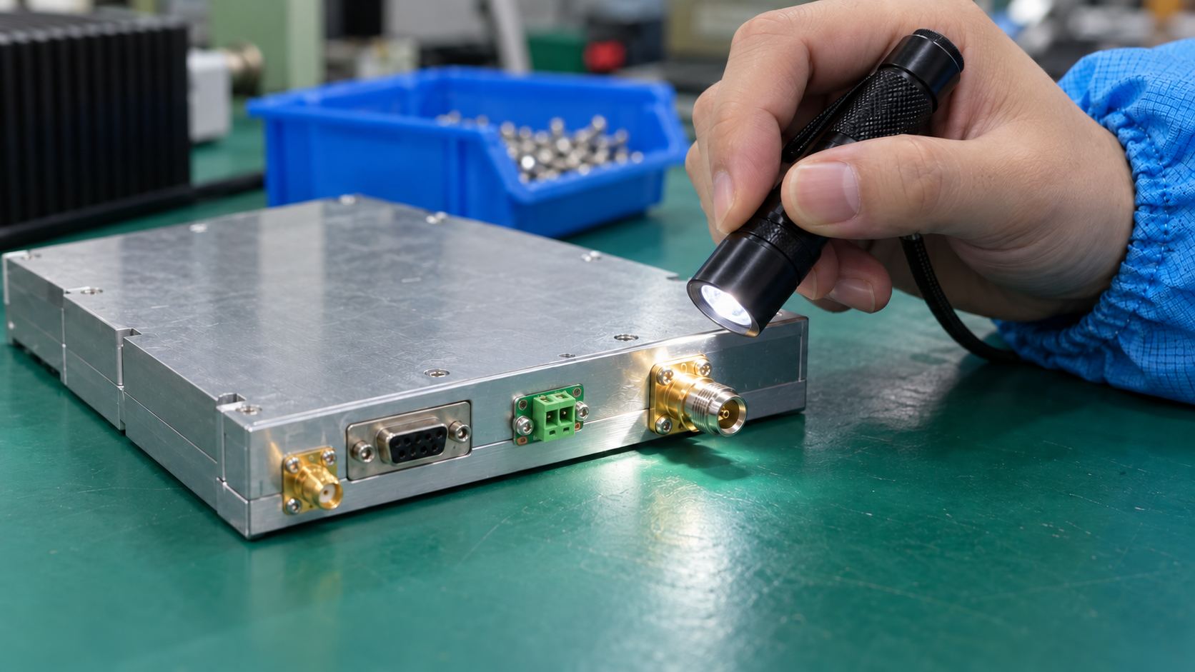
After the stress, repeat the baseline. Compare the data instead of doing only a power-on check. Inspect RF ports, screws, fans, wires, baseplate contact, case joints, and seals. Keep any fault, repair, and retest with the first result.
Buyers can use our RF power amplifier test-data checklist to set the RF record. Teams that need a wider system review can also use the guide for checking amplifier test data during integration.
A pass label needs data behind it. Set the baseline, live log, and final checks before the chamber or road test starts.
5. Does the Report Cover the Unit You Will Receive?
A detailed report is useful only when it matches the order. The first page should list:
- full model, hardware build, and firmware or control build;
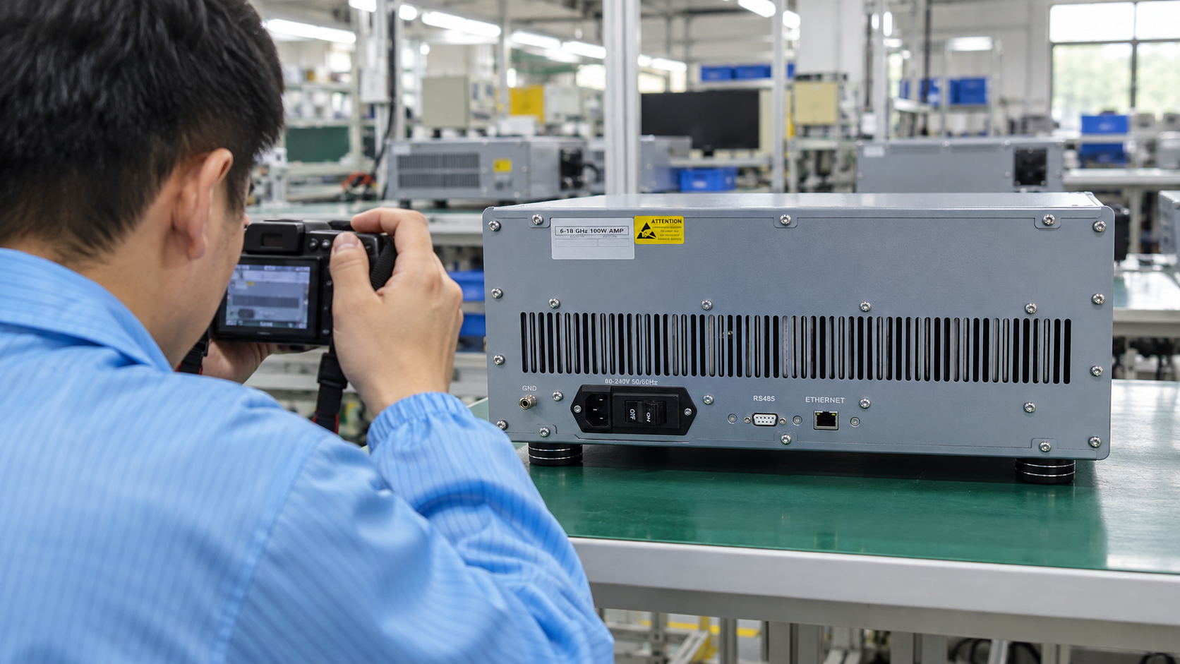
- serial number, options, RF ports, cooling method, and case;
- test date, mount, cables, fixture, and test points.
Photos help when they show those details.
If the supplier tested a similar platform, ask for a clear match statement. It should list what is the same and what is different between the test unit and the ordered unit. A shared case or family name does not prove that the RF path, cooling, mount, or control is the same.
The report should also keep the test profile, fixture, axes, screw torque when needed, sensors, tool list, RF test point, cable loss, load, and pass limits. A plain “PASS” line gives a result but not enough facts for a later review.
Review any change made after the test. A new RF port, heat sink, fan, screw, board build, material, source, control release, or work step may change the tested path. A small change may need a paper review. A larger change may need a short check or a full retest. Link that choice to the risk created by the change.
Qualification and factory tests have different jobs. Qualification checks a set design under selected stress. Factory tests check the units that ship. The RF amplifier production-testing guide covers test limits, station control, guard bands, and fault records. For rack gear, the five-document checklist helps buyers collect drawings, ports, use notes, and test records.
Traceability decides if the report fits the order. Put “tested build” and “build to be shipped” on the cover. Then review each difference before you accept the report.
6. What Should Go into the RFQ and Approval Plan?
Describe the job before you name a standard. State the site, mount, cooling path, signal, run time, standby state, and shipping state. Keep use, storage, and shipping limits in separate fields.
If the contract names a standard, add its revision, method, level, time, sample state, and build. A standard family name can point to many test levels. Mark any open field for joint review so each supplier does not make a different guess.
Records to Request
State what the supplier must send. The need may be:
- a report from the same platform or a test on a project sample;
- one batch record or data for each unit;
- raw plots, photos, tool records, fault notes, repair notes, and retest data.
These records take different amounts of work. Agree on them before the quote.
Pass Rules
Name the checks needed before, during, and after each stress. Tie each limit to the project spec or an agreed test plan. Also state what to do after an alarm, loss of control, protection trip, failed retest, or build change.
| RFQ field | Buyer states | Supplier confirms or sends |
|---|---|---|
| Site | Cabinet, vehicle, mobile rack, or other place | Proposed build and test boundary |
| RF state | CW or pulse mode, power, duty cycle, run time, and start/stop plan | A test state that the lab can repeat |
| Stress | Use, storage, and shipping needs | Method, level, time, and sample count |
| Mount and cooling | Format, direction, baseplate, air, or liquid cooling | Fixture, setup, and known gaps |
| RF and DC checks | Frequencies, output, gain, current, alarms, and protection | Before/during/after data and test point |
| Report ID | Model, build, and project number | Serial number, build, date, and setup |
| Pass rule | Approved limits | Result, fault, repair, and retest record |
| Change rule | Changes that need a new review | Notice, risk review, and proposed check |
Our custom RF amplifier RFQ guide covers the other RF, power, control, and size inputs needed for a quote. Add this test table and a setup sketch when heat, motion, shipping, or water can affect approval.
Write each need so both sides can check it. Send CorelixRF the frequency range, output target, signal, mount, cooling path, site, and required records through our RF project inquiry page. The model, test scope, pass limits, and records must be set for the project.
Frequently Asked Questions
Q1: Does an amplifier still need an environmental test after a full-power room test?
A room test covers only that setup. Add other tests when the site risk, contract, or approval plan needs them.
Q2: Can a storage temperature range be used as an operating range?
No. Storage often means the power is off. An operating limit also depends on RF output, supply, cooling, load, control, and protection.
Q3: Should RF performance be checked again after vibration?
Yes, when the plan needs proof that RF and DC values stay within the agreed limits. Set the checks first and use the same setup before and after the test.
Q4: Is a report that says “complies with a standard” enough?
Usually not. Check the standard revision, method, level, time, mount, unit state, tested build, pass limits, faults, and data.
Q5: Does every amplifier need heat, humidity, vibration, shock, and salt tests?
No. Choose tests from the site, system boundary, fault risk, and purchase terms. A test that does not match the job adds cost but gives no useful answer.