
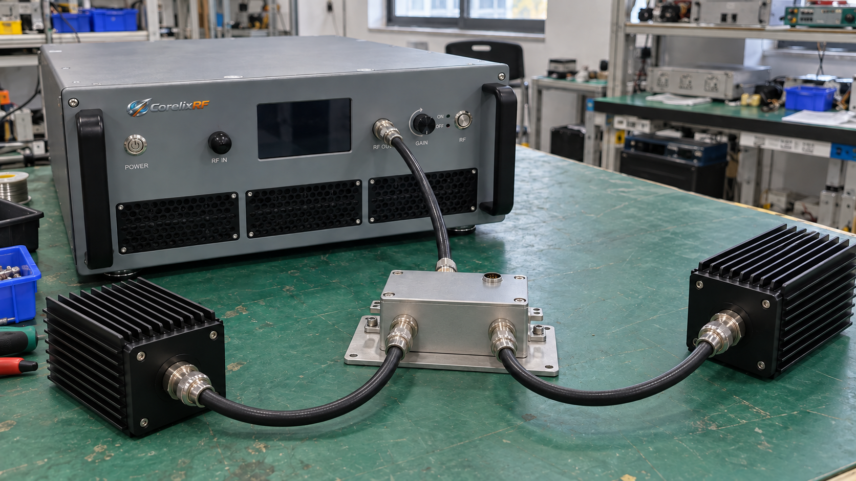
RF switches let one RF power amplifier serve different antennas, dummy loads, or test stations in turn. Choose a switch by checking each branch’s frequency, power, load, and control needs. Then compare switching speed, path loss, and interfaces against those requirements.
A switch may carry more power through a settled path than it can handle while changing paths. Check both ratings before placing it at an amplifier output. The right choice also depends on whether your system can pause RF during each change.
1. Which Loads Will Your RF Switches Connect?
Start with a connection diagram. Connect the amplifier output to the switch’s common port. Each branch leads to an antenna, a suitably rated dummy load, or another equipment input. In this setup, RF switches select one branch at a time:
Amplifier output → RF switch common port → Selected load A, B, or C
When selecting an RF power amplifier, list what each branch must do. Because loads differ, each branch may need its own frequency and output power settings. Cable lengths, adapters, and connectors can vary too. Check these details before comparing switches and accessories.
For example, one branch might feed a test load and another an antenna. For that antenna branch, check the amplifier and antenna matching requirements. When selecting that branch, use frequency and power settings within its operating range. However, a wider amplifier band does not extend a load’s usable band.
Reserve extra ports for planned expansion. An extra test station may affect which setup fits, so include it before you buy. Also define routing at startup, in standby, and after a fault. Do not assume a switch returns to a dummy load when power fails.
If several loads need power at once, assess a separate power distribution network. Check each branch’s power and isolation needs as part of that design.
2. Can the RF Switch Handle Your Power?
Check Through-Power and Switching Ratings Separately
After a switch settles, RF passes through an established path. During switching, that connection changes. Check the permitted power in both states; a through-power rating alone does not cover a change of path.
Cold switching means removing RF before changing the switch state. Hot switching means changing state while RF is present. If a datasheet gives only a settled-state rating, ask for its switching limits. Do not infer hot-switching capability from that number.
State whether your system can pause RF output while changing paths. If RF must remain on, check the model’s hot-switching limits under those conditions. Amplifier protection does not replace a switch’s own rating.
Match the Rating to CW or Pulsed Operation
For continuous-wave operation, check the required power, frequency, and temperature together. The switch must carry that power for as long as your system needs. Its mounting and cooling must also match the conditions behind the rating.
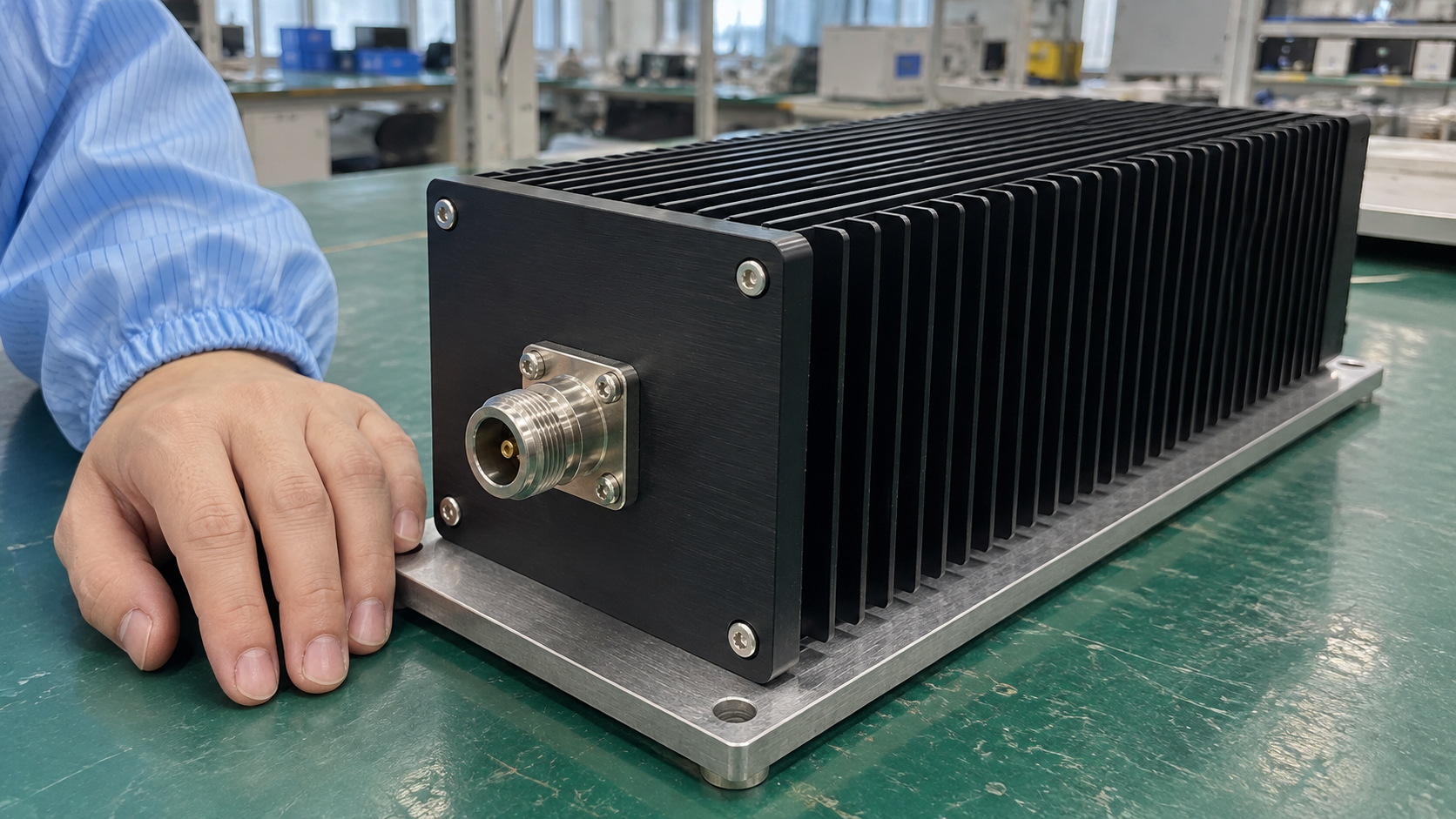
For pulsed operation, provide peak power, average power, pulse width, and duty cycle. A low average value can hide a high pulse peak. Check both against the stated limits before choosing a switch.
Use the highest output your system can reach when checking power ratings. Software may allow more drive or gain than a normal test uses. If those settings are available, account for them or define limits that keep operation within the agreed range.
Read each power rating with its frequency, temperature, waveform, and load conditions. A value at one frequency may not apply across your full band. Compare RF switches using the same operating conditions.
3. Should You Choose Mechanical or Solid-State RF Switches?
Shortlist RF switches that meet your frequency and power needs. Then compare how often each path must change. A few station changes per day place different demands on hardware than a repeated automated test sequence.
For a mechanical switch, check contact movement, settling time, and switching life under the stated conditions. A solid-state switch controls RF through electronic devices rather than moving contacts. However, its power, linearity, bias, and heat limits still need checking.
| Comparison | What to Check for a Mechanical Switch | What to Check for a Solid-State Switch |
|---|---|---|
| Switching timing | Actuation and contact settling within the allowed time. | Switching and RF settling within the allowed time. |
| Frequency of use | Life data for the stated power and switching conditions. | Electrical and heat limits during repeated use. |
| RF performance | In-band loss, isolation, and repeatability. | In-band loss, isolation, and linearity. |
| Installation | Drive, position feedback, space, and service needs. | Bias supply, control levels, space, and cooling. |
For occasional station changes, a mechanical switch may suit a setup that can pause RF. For frequent changes with short pauses, review solid-state options too. Then check each candidate’s power, loss, and isolation ratings. State the expected number of switching cycles and acceptable maintenance needs.
Check how the supplier defines switching time. A control-level change and a software command may mark different starting points. RF settling can also take time after a command arrives. Allow enough time for the full path to become ready.
4. Do Path Loss and Isolation Meet Each Branch Requirement?
Selected Path: Check the Power Available at the Load
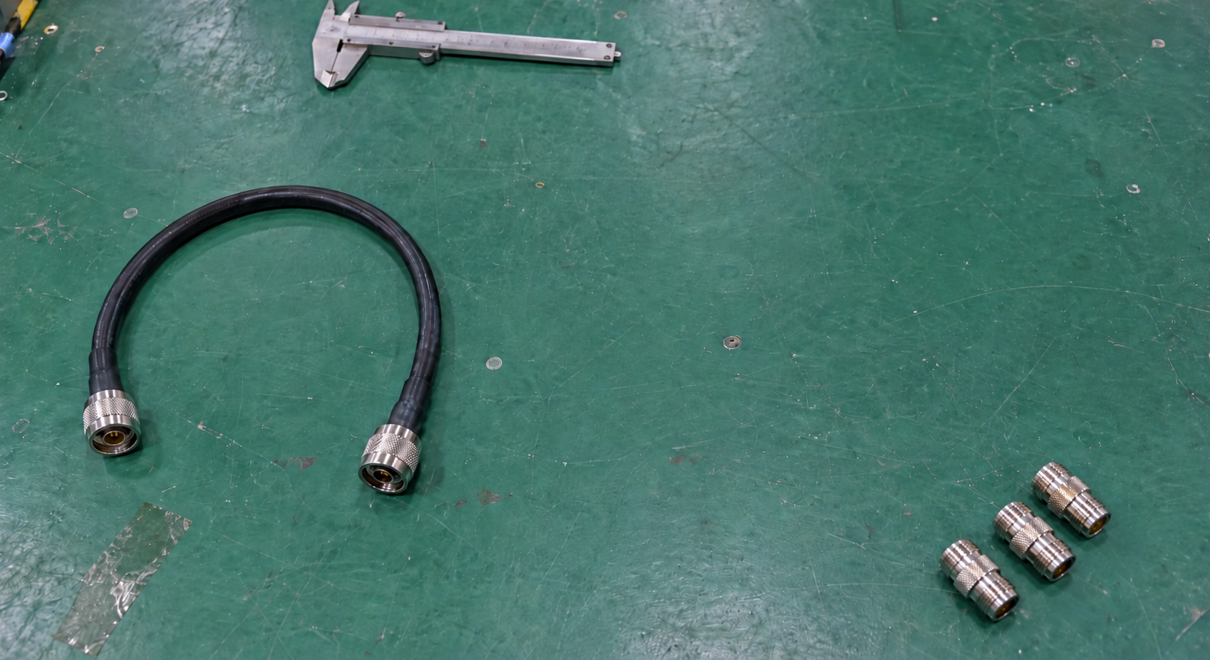
RF passes through the switch, cables, and adapters before reaching a load. State where you need the specified power: at the amplifier output port or at the load input. Use that same reference point when comparing options.
If power must reach the load, include losses through the selected path. Otherwise, an amplifier could meet its output rating while too little power reaches your equipment.
Check each branch separately. For example, longer cables, extra adapters, and different switch ports can change path loss. For broadband use, check loss across your working band instead of using one center-frequency value.
Unselected Paths: Check Leakage and Termination
Unselected ports still need a leakage check. If a branch feeds equipment with a limited input rating, compare leakage with that limit. Use the isolation figure for the ports involved.
RF switches may have separate isolation ratings for common-to-branch and branch-to-branch paths. Match the figure to your actual connection. Otherwise, you may choose a large isolation number that describes a different path.
Also check what happens at unselected ports. A switch may use a reflective design, internal terminations, or external terminations. An internal termination has its own power limit. Confirm that limit before treating it as a load for full amplifier output.
Antenna, cable, and load matching can also affect leakage and power handling. If abnormal loads are possible, review the amplifier’s VSWR and reflected-power protection requirements alongside switch ratings. Define the allowed conditions for each device.
5. How Should Your Amplifier and Switch Work Together?
For RF switches that require cold switching, use a sequence that removes RF before changing paths:
- Remove the RF signal and confirm that conditions at the switch meet its switching requirements.
- Change the selected path.
- Confirm that the target path is in position, the load is ready, and the specified settling time has elapsed.
- Restore output using the frequency and power settings permitted for that branch.
Before using that sequence, define how your actual equipment removes RF. After an output-off command, use its documentation and verification measurements to confirm when switching can begin. Command acceptance alone does not prove that RF is absent or a new path has settled.
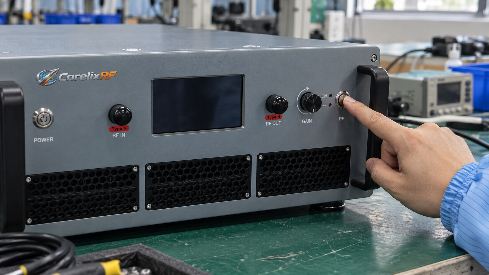
Also define what happens if switch position remains unknown or communication fails during a change. The response depends on available interfaces and control logic. Do not assume an amplifier can detect an external switch’s state on its own.
Before setting delays, check your chosen equipment’s actuation, settling, and feedback requirements. During commissioning, check how amplifier input drive works with that sequence. Avoid copying a fixed delay from another system without checking its basis.
6. What Should You Prepare Before Requesting a Quote?
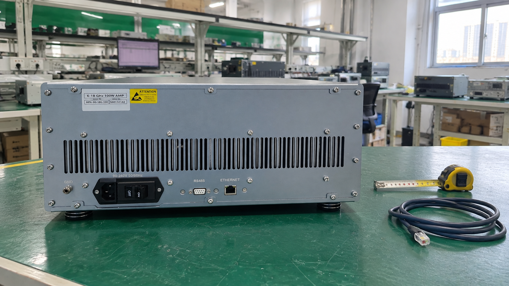
Although power and port count help narrow your choice, they cannot show whether all parts will work together. For RF system integration, draw the amplifier, switch, cables, and loads on one connection diagram. Then add the requirements below before requesting quotes for RF switches.
| Requirement | Information to Provide | What It Helps Check |
|---|---|---|
| Operating frequency | Overall band and the band used by each branch | Frequency coverage of the common path and individual branches |
| Output power | Target power at the load and maximum possible amplifier output | Power ratings and path loss |
| Waveform and operating duration | CW or pulsed operation, peak and average power, pulse width, duty cycle, and duration | Applicable power and thermal conditions |
| Output paths | Number of loads, purpose of each branch, and connection diagram | Port count and routing |
| Load conditions | Load type, matching data, and unselected-port state | Termination and isolation requirements |
| Switching needs | Switching frequency, permitted interruption, and whether RF is present during switching | Switch type and switching conditions |
| Installation | Connectors, cables, available space, ambient temperature, and cooling | Physical fit and whether the rating conditions apply |
| Control | Control interface, state feedback, default state, and fault handling | Responsibilities of the amplifier, switch, and control system |
If you have chosen an amplifier or switch, include its documentation. Also mark which parts are fixed and which can change. Send your connection diagram and operating conditions to CorelixRF to discuss amplifier requirements.
Frequently Asked Questions
Q1: Can one amplifier power several loads at the same time through a switch?
The RF switches discussed here select one output path at a time. If several loads need power at once, use a separate power distribution design. Check its power, isolation, and load conditions for every branch.
Q2: Can an input switch replace a switch at the amplifier output?
An input switch selects which signal enters an amplifier. An output switch selects which load receives its output. Changing an input signal does not route that output between test stations.
Q3: Does amplifier VSWR protection allow switching with RF power present?
No. Instead, check the switch’s hot-switching rating and its stated conditions. Amplifier protection addresses abnormal loads; it does not prove that an external switch can change state while carrying RF power.
Q4: Can unselected ports be left open?
Before leaving a port open, check the switch design, supplier’s termination rules, and your isolation needs. Some setups need external terminations. Internal terminations also have power and frequency limits, so check those before use.
Q5: Can the existing setup stay the same after fitting a higher-power switch?
Before installing it, recheck frequency coverage, path loss, port assignments, connectors, and control logic. A new switch may have different actuation, settling, or feedback needs. Update the sequence where those requirements change.