
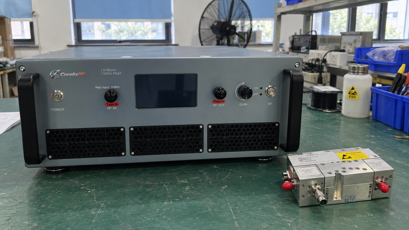
When choosing a power amplifier vs low noise amplifier, start with the job of the RF stage. A power amplifier (PA) supplies RF power to a load. A low noise amplifier (LNA) boosts a weak signal while adding little noise. These goals explain why PAs often serve transmit paths and LNAs often serve receive paths.
Both types have gain, noise, and output limits. So a match in frequency and gain is only a first check. You also need to know the input level, the required output, and how much noise or distortion the system can accept.
1. Power Amplifier vs Low Noise Amplifier: What Changes?
The job of the RF stage
Both devices draw energy from a DC supply to amplify an RF signal. A PA must supply the required output power while meeting limits on distortion and heat. An LNA must raise the signal level with low added noise.
That does not mean a PA can ignore noise or an LNA can ignore power. For example, an LNA still needs enough output range to drive the next stage. In fact, its gain can be high while its usable output is too low for that task.
The first checks to make
| Selection question | PA emphasis | LNA emphasis |
|---|---|---|
| What must the stage do? | Supply the required RF power | Raise a weak signal with low added noise |
| Where is it often used? | Transmit output stage | Receiver front end |
| Which output limit matters? | Power at the allowed distortion level | Output range for later stages and strong signals |
| How should you judge gain? | Against the drive you have and output you need | Against the noise budget and signal range |
| What else should you check? | Supply, heat, efficiency, and load | Noise figure, linearity, supply, and RF ports |
Use the table to choose a starting point. Then compare datasheet limits under the same test conditions.
2. Where Do PAs and LNAs Sit in an RF Signal Chain?
The transmit path and driver
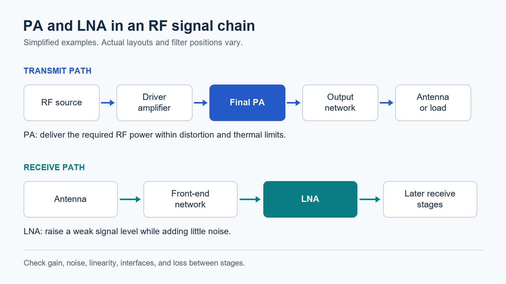
A transmitter may need a driver between its RF source and final PA:
RF source → driver amplifier → final PA → output network → antenna or load
The driver must supply enough signal for the PA. Its required output also depends on loss between the two stages. If the driver clips or compresses first, it can limit the whole transmit path.
For this reason, check drive at the PA input port. Do not treat the driver’s output and the PA’s input as the same point when a cable or filter sits between them.
The receive path and front end
A common receive path has a different order:
Antenna → front-end network → LNA → later receive stages
The front-end network may contain a filter, switch, or protection circuit. It can reduce unwanted signals, but its loss also affects the signal that reaches the LNA. Later stages may mix, amplify, or convert that signal.
However, these are simplified paths, not fixed layouts. Filter placement and built-in stages vary. Mark each input and output test point on your own block diagram, along with the loss between them.
3. Why Can Equal Gain Give Different Results?
What gain tells you
Within the linear range, you can estimate power with:
Output power (dBm) ≈ input power (dBm) + gain (dB)
Use gain for the stated frequency, input level, and test conditions. As drive rises, an amplifier can leave its linear range. As a result, adding small-signal gain to input power then overstates the output.
For example, assume two devices have these values at the same frequency, supply, temperature, and impedance:
| Assumed value | Amplifier A | Amplifier B |
|---|---|---|
| Small-signal gain | 20 dB | 20 dB |
| Output P1dB | +5 dBm | +25 dBm |
| Estimated output at −40 dBm input, in linear operation | −20 dBm | −20 dBm |
These are hypothetical values for a calculation. They are not product specifications or test results.
What gain leaves out
At 0 dBm input, adding 20 dB gives +20 dBm. You cannot assume Amplifier A will reach that output with its stated gain. The estimate lies far beyond its compression point. Amplifier B has more margin, but you still need data for its actual response.
Also, this table gives no noise figure. Either device could exceed a receiver’s noise budget. Check RF amplifier gain and noise figure as separate values, then check the output limit.
4. Why Does Noise Figure Matter for an LNA?
Added noise and weak signals
Noise figure describes the loss of signal-to-noise ratio under stated reference conditions. A conventional LNA raises both the wanted signal and the noise at its input. It also adds its own noise. A low noise figure limits this added loss of signal quality.
An LNA cannot restore the signal-to-noise ratio already lost ahead of it. Nor can one noise figure tell you the sensitivity of a whole receiver. Bandwidth, path loss, later stages, and the required signal quality also matter.
Check noise across the band you plan to use. However, a good result at one frequency may not hold at the band edges.
Gain and loss in the receive path
Early gain reduces the share of noise that later stages add to the total noise budget. However, loss ahead of the LNA uses part of that budget before gain can help.
For example, a filter before the LNA adds loss but may reduce strong unwanted signals. Moving it after the LNA changes this tradeoff. Choose its position from both the noise budget and the expected interference.
For LNA selection, check front-end loss, gain, and added noise together. Use the same receiver reference plane for each check.
5. Which PA Output Power Rating Should You Use?
Rated power, P1dB, and saturation
First, ask what the quoted power means. It may be output at a set gain compression, saturated output, or power that meets a stated distortion limit.
Output P1dB is the actual output where gain has dropped 1 dB below its small-signal value. In contrast, near saturation, more drive adds little output. Neither rating alone tells you the usable power for every signal type.
Keep the test conditions next to each power value. Otherwise, two similar numbers may describe quite different uses.
Power for your signal and load
For a modulated signal, state its average power, peaks, bandwidth, and distortion limits. If error vector magnitude (EVM) is a pass/fail limit, use the EVM-versus-output-power curve to find the usable range. The PA may need to run below its compression or saturation rating to meet that limit.
For pulses, also state pulse width, repetition rate, and duty cycle. Peak power does not tell you the average load or prove that a PA can run at that power in continuous-wave mode.
Finally, define where you need the power: at the PA port, a test plane, or an antenna feed. Loss after the PA raises the output needed at its port. Ask for data at that operating point; do not assume one backoff value suits all waveforms.
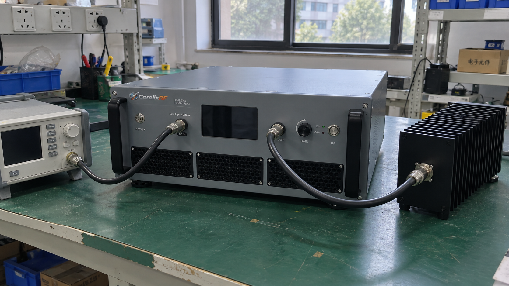
6. How Do Strong Signals Affect Both Types?
Transmit distortion and receive blockers
A PA can meet a power target yet fail a distortion limit. Depending on the signal, checks may cover EVM, adjacent-channel leakage, harmonics, or intermodulation.
A receiver can face a weak wanted signal and a strong unwanted signal at once. That unwanted signal, or blocker, can drive the LNA into compression. Multiple signals can also create intermodulation products in the wanted channel.
So low noise alone is not enough. The LNA needs the linear range to handle the signals at its input without unacceptable distortion.
Compare like-for-like test results
Check whether compression and intercept values refer to the input or output. Also compare frequency, tone spacing, tone levels, bias, and temperature where these apply. Different test conditions can prevent a fair comparison.
An intercept point is an extrapolated measure of distortion, not power that the device can deliver. Likewise, an absolute-maximum input rating is a stress limit. It does not define the input range for low distortion.
List wanted-signal levels and blockers separately. Then account for any filter or protection circuit ahead of the LNA.
7. Which Operating Conditions Must Match?
Frequency range and RF ports
Check the full required operating frequency range, rather than one point near its center. Review gain, noise, output, and matching wherever they affect the stage’s job.
RF ports also need more than plugs that fit. Check impedance, mismatch limits, and stability in the assembled system. For example, you may need external matching or DC blocking, even if the connectors mate.
Supply, bias, and heat
Use the specified supply and bias scheme. Some devices need external bias parts or a set startup sequence. Others include those functions. The PA or LNA label does not tell you which applies.
Check these items against your installation:
- Supply voltage and current at the intended RF drive.
- Bias, enable, and startup needs.
- Stated limits for ambient, case, or baseplate temperature.
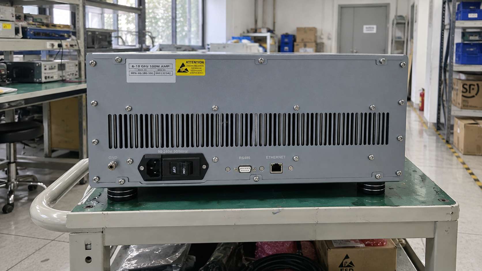
- Mounting and cooling used to reach rated output, including PA rack cooling requirements in a rack.
- RF input limits and stated load restrictions.
Also, keep typical curves separate from guaranteed limits. A typical room-temperature curve can guide a shortlist. To set acceptance limits, you need evidence for the range of conditions you will use.
8. Can You Swap a PA and LNA or Use an LNA as a Driver?
A PA in a receive stage
A PA is usually a poor starting point for a noise-sensitive receive stage unless its data support that use. Matching gain and frequency does not prove low-noise performance.
Check noise figure, linearity, input limits, and RF ports against the receiver’s needs. If noise data are missing, ask for them before you qualify the part. After all, extra output power cannot make up for too much added noise.
An LNA as a driver
Some LNAs have enough usable output and linearity to drive a later stage. Check that stage’s input needs, the signal peaks, and the loss between the devices.
For a proposed swap, compare:
- Usable drive across the full band.
- Distortion at the required output level.
- Input range, gain, and RF ports.
- Supply, control, and mounting needs.
A device that works as a driver may still be unsuitable as a final PA. Therefore, tie each choice to one defined stage and set of operating conditions. Resolve missing data before you approve the swap.
9. How Do You Choose for a Specific RF Task?
Start with the system requirement
The following are selection examples, not customer results.
For a receiver input, state the minimum wanted signal and the expected interference. Then check the noise budget and usable input range.
For a transmit output, state the required power, test plane, waveform, and distortion limits. Next, check those needs at the intended supply and thermal conditions. If you are replacing an installed PA, also check replacement compatibility with its driver, controls, and mounting.
For a driver, start with the next stage’s required input. Add the loss between stages. Then check whether the proposed device can supply that drive with acceptable distortion.
Build a shortlist with evidence
| RF task | Starting point | Reason to reject or pause | Data needed |
|---|---|---|---|
| Noise-sensitive receiver input | LNA | Too much noise or poor blocker handling | Noise and linearity at the intended conditions |
| Transmit power output | PA | No support for the waveform or thermal operating point | Output and distortion for the intended use |
| Drive for another RF stage | Driver, gain block, or suitable LNA | Too little usable drive or incompatible ports | Output, gain, distortion, and port data |
Keep a column for missing data. Request those data before qualification, and reject a device if it fails a mandatory limit.
10. What Should You Put in an Amplifier RFQ?
Describe the signal and output you need
“RF amplifier with high gain” gives a supplier too little detail. Instead, send a short requirement sheet with:
- Operating band and signal bandwidth.
- The stage’s position in a block diagram.
- Minimum, nominal, and maximum input levels.
- Required output power and its reference plane.
- Waveform, peaks, and operating mode.
- Noise, distortion, and blocker limits where relevant.
- Supply, RF ports, available space, and cooling.
Add pulse timing if you use pulses. Also separate mandatory limits from preferred features, so the supplier can see which differences rule out a part.
Ask for data at the proposed operating point
Request the exact model and revision, its datasheet, and data for any limits the datasheet does not cover. Also state whether typical results are enough for evaluation or you need guaranteed limits for acceptance.
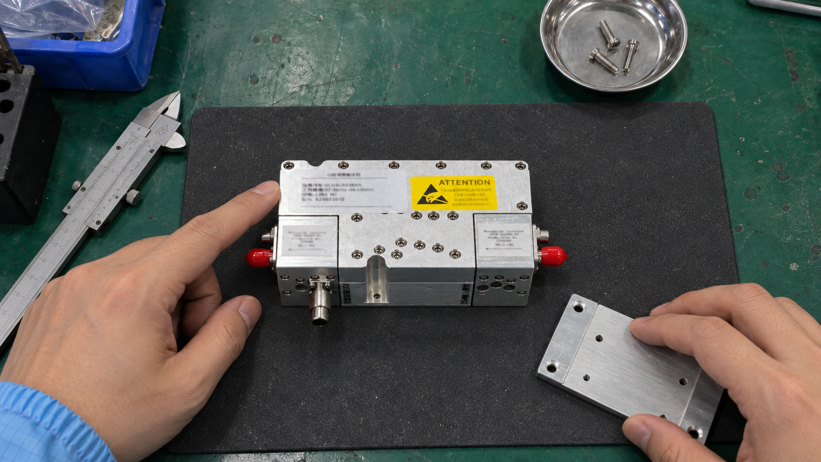
For a CorelixRF PA enquiry, start with our RF power amplifier range. Send your requirement sheet with the enquiry, including the proposed configuration and operating conditions.
Frequently Asked Questions
Q1: Is a low noise amplifier a type of RF amplifier?
Yes. An LNA is an RF amplifier whose design gives priority to low added noise. You still need to check its gain, output range, linearity, and installation needs.
Q2: Does more LNA gain always improve receiver sensitivity?
No. More early gain can reduce the effect of noise from later stages. But too much gain can overload those stages when a strong signal arrives. Choose gain within the full receiver noise and signal-level budget.
Q3: Can you use a low noise amplifier in a transmitter?
Yes, if it meets that stage’s needs. For example, a driver needs enough usable output, low enough distortion, and compatible ports. The LNA label alone proves none of these.
Q4: Is a power amplifier always Class AB?
No. “Power amplifier” names a function; class describes how the stage operates. Class AB is one option. Check the actual circuit and its performance instead of inferring class from the PA label.
Q5: Why does an LNA datasheet give output power and P1dB?
An LNA has a finite output range. For this reason, compression data help you assess strong-signal handling and possible driver use. Check these values alongside noise figure when choosing the device.