
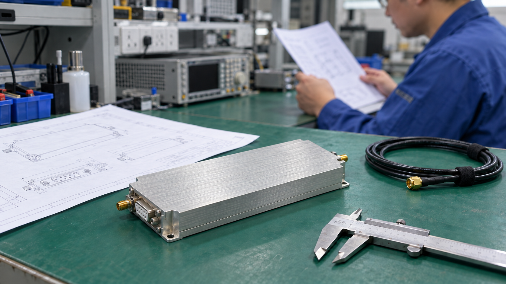
An RF amplifier replacement can meet its rated power on a test bench yet fail in your equipment. The installed driver may not supply enough input power. A port in a new place may need a new cable. A mounting plate may change the heat path.
For an RF power amplifier replacement, resolve each difference before you accept the new unit. Start with the equipment’s fixed requirements. Then rule out units that cannot meet them. Test the ones that remain in stages. The result should show what you can retain and what must change.
1. Set the Baseline for Your RF Amplifier Replacement
Begin your RF amplifier replacement review with the reason for the change. Replacing an obsolete model differs from replacing a failed unit with an unknown fault. If you need more output or a wider band, set those new targets too. State this goal in the brief so buyers and engineers work toward the same result.
Next, list the old model and revision. Collect the system spec, RF diagram, mounting drawing, and past test records. If the old amplifier still works, measure its output to help assess the installed chain. Keep those results separate from the required performance. Wear in an old unit must not lower your target.
Also mark gaps in the records. For example, one supply voltage reading does not prove the full range that the amplifier can use. A photo alone cannot prove every port detail. Keep measured values, stated limits, and unknowns in separate fields.
Use one baseline sheet to show which limits the new unit must meet.
| What must stay | What to check | How it shapes the shortlist |
|---|---|---|
| RF needs | List frequency points, waveform, output, and duty. | Compare ratings under the same conditions. |
| Available drive | Check input power across the band. | The new unit must reach target output with that drive. |
| Power and cooling | Check the supply, wiring, heat path, and site conditions. | Include all needed changes in the scope. |
| Installation | Check mounts, ports, cable routes, and service access. | Review the whole installed system. |
| Functions and limits | List the functions and limits the system needs. | Rule out a unit that cannot meet a fixed need. |
For a CorelixRF unit, find the model in the datasheet library and check that its revision matches the proposed build. Keep the old system baseline beside it during the review.
2. Rule Out Units That Fail the Fixed Requirements
Before designing brackets or ordering adapters, resolve three questions that can stop an RF amplifier replacement.
Can the new unit meet your output needs?
Write down what the power figure means. P1dB is the point where gain is 1 dB below its small-signal value. In contrast, saturated output is a different rating. For peak power, state the pulse or waveform conditions. For average power, compare ratings on the same basis.
A higher number does not make two different ratings a fair match. Compare frequency, waveform, duty cycle, temperature, and output reference plane. Also separate typical values from guaranteed limits. If signal quality limits usable output, check EVM versus output power for your planned signal.
If the test conditions are missing, keep that comparison open. Do not favor an unproven value over a lower figure backed by the right test data.
Can your driver supply enough input for an RF amplifier replacement?
Check drive power at the new amplifier’s input port. Include loss from retained attenuators and cables, plus any new transitions. Because the path can add loss, the signal generator’s setting alone cannot answer this question.
Then compare available drive with input-versus-output data at the required operating point. Use measured small-signal gain for an early estimate in the linear region. Near compression, use data from the intended operating point. Higher gain may require reduced drive or added attenuation. In contrast, lower gain may leave the existing driver short of power.
If the test needs a different driver to reach the claimed output, flag that change at once. That test supports the setup used, but it does not prove that your current driver will work.
Which required limits or functions lack proof?
Check the maximum input power, allowed loads, duty, and temperature. Also check the functions your system needs. Keep normal limits separate from ratings that apply only under special conditions.
Rule out a unit that lacks a function your equipment needs. However, a feature with no proof remains unknown. Treat a custom feature as a separate design change. Then agree on its scope and the tests it must pass.
3. Trace Each Change Through the Installed System
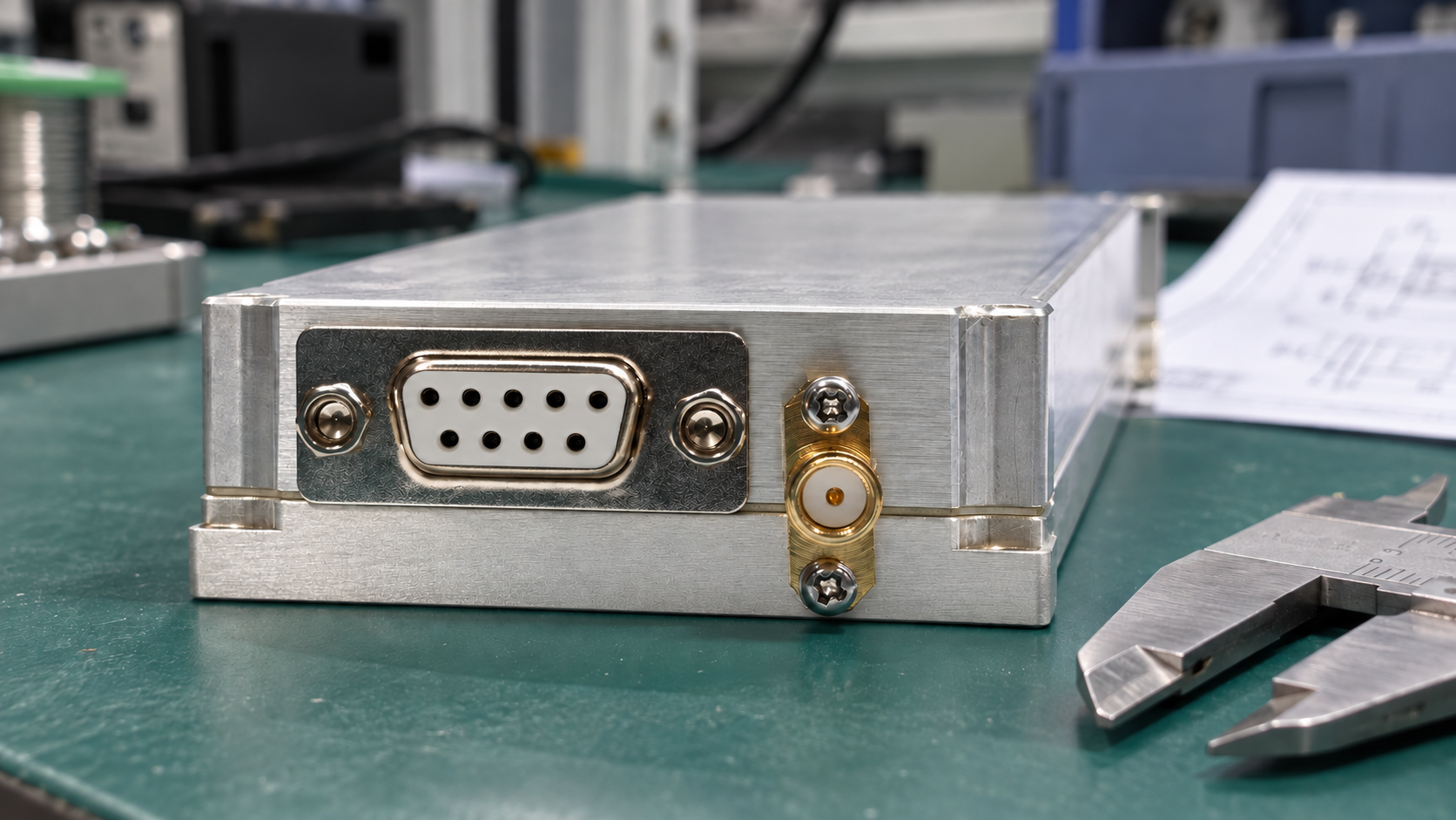
Once a unit passes the fixed checks, map its differences onto the installed system. Review each new bracket, cable, or supply as part of that system. Each part can affect other checks in the review.
Follow a connector change through the RF path
At both RF ports, check impedance, connector type, and mating gender. Also check port direction and operating ratings. Microwave and millimeter-wave equipment may require separate reviews of coaxial and waveguide interfaces. In either case, get the correct flange and port drawings.
If you need an adapter, add it to the RF diagram. Check its frequency and power ratings. Then check cable routes and space for access. Then define the output test point: at the amplifier port or after the installed RF path. Record path loss and how you correct for it. Use the same basis so you can compare tests.
Follow a supply change through wiring and installation
Check voltage range, polarity, and operating current against the retained supply. Also check the stated transient demand. Next, review voltage at the amplifier terminals under the intended load. Check wiring and contacts too, even when connector housings look unchanged.
If the unit needs a new supply, include its mounts, wiring, and heat in the revised setup. Also get the model’s wiring and startup guide. Do not copy another amplifier’s startup sequence or guess a reserve percentage.
Follow a mounting change through the thermal path
An adapter plate may align the mounting holes. However, it can change how a baseplate-cooled module meets its cooling surface. Before you accept the new mount, check the required interface material and surface. Follow the stated fastener instructions.
Then check the full space needed. Include protruding ports, connected cables, cable bends, and space to remove the unit. A body that fits can still leave no room to connect or service it.
For rack installations, review RF amplifier cooling requirements against the actual inlet, exhaust, and neighboring equipment. However, two units with equal RF output may produce different amounts of heat. A cold-plate test supports the tested setup. It does not prove cooling performance inside the original enclosure.
Record each proposed change, its owner, and the test it affects. If an RF amplifier replacement needs more work than the project allows, review the choice before ordering a sample.
4. Record Your RF Amplifier Replacement Decision
At this stage, record a decision and the conditions that remain open. “Looks suitable” provides neither.
| Review result | What you know | Next action |
|---|---|---|
| Ready for sample tests | No fixed conflict found. The required checks have supporting data. | Order the agreed sample build and run the test plan. |
| Changes needed | The new unit needs defined changes to the current setup. | Agree on drawings, owners, costs, and tests to repeat. |
| Missing facts | A required check still lacks proof. | Get the named document or test result before you decide. |
| Does not fit | The unit fails a requirement that must stay fixed. | Remove it from the current shortlist. |
“Ready for sample tests” means you can test a sample. It does not prove that the unit will work in your system.
Next, make each open item specific enough to close. For example, replace “confirm cooling” with a request for the mounting guide and installed thermal test conditions. Replace “check connector” with the missing part specification or flange drawing. Give each owner a clear list of evidence needed to close the action.
5. Test Your RF Amplifier Replacement in Three Stages
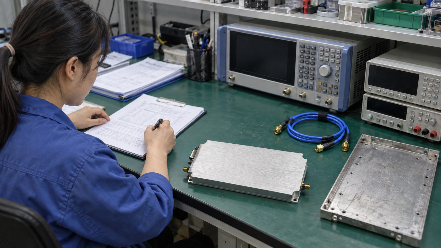
Agree on limits before testing. Base pass limits on the system needs and the confirmed unit spec. Also record measurement planes, frequency points, waveform, duty, and temperature. State which setup revision you tested. Include calibration records and cable corrections. Agree on how to judge results near a limit.
- Bench tests. Test the unit at agreed operating points. Record the setup. At each point, record input power alongside output and relevant signal-quality results. List any test supply, driver, or cooling setup that differs from the planned build. Those changes limit what this stage can prove.
- Installed checks. Repeat the affected checks with the retained driver, final wiring, and actual mounts. Use the normal enclosure setup. Measure the electrical and thermal conditions in the plan. A test with covers off cannot prove a requirement for the closed enclosure.
- System acceptance. Run the system’s agreed operating sequence and acceptance tests. Check that the full assembly meets its requirements. Record each result outside the limits and the agreed next action. Tell the equipment owner which results came from the supplier and which came from installed tests.
When a stage fails, link the result to a specific requirement and setup. If changing attenuation resolves a drive issue, update the RF chain and repeat affected checks. If changing the cooling arrangement resolves a temperature issue, retain that arrangement in the accepted build. Otherwise, the delivered replacement may differ from the one that passed.
6. Keep the Build That Passed
The accepted RF amplifier replacement includes more than a model number. Record the amplifier revision, supply, cables, adapters, and mounting parts. Keep the setup guide and test results with that list.
Use this record for later build or service orders. If an installer receives only the amplifier model, the approved attenuation or mounting change can disappear from the next build. To prevent that loss, attach the drawings and parts list to purchase and service records.
Review later part changes against the accepted requirements. For example, a different RF cable may change the measurement path. A revised mounting plate may require a thermal check. Decide which earlier evidence still applies and list the checks that need another run.
If the old equipment still works, agree on a rollback plan before testing a sample. State when to end a failed trial and how to restore the approved setup. Assign the rollback work to the team that installs the unit.
7. Send the Supplier the Unresolved Questions
Use the RF amplifier RFQ checklist to list the old model, system needs, and RF diagram. Include power and cooling data plus mounting drawings. Also attach the review decision sheet and proposed test plan.
State what must stay fixed, what can change, and what remains unknown. For each open item, ask the supplier for the relevant document or a proposed test. The quote can then state the full scope, including the work needed to fit and test the new unit.
For a CorelixRF review, submit the existing configuration and replacement requirements, including any fixed need that could rule out the unit. Use the response to decide whether you can start a defined sample test.
RF Amplifier Replacement FAQ
Q1: Can two amplifiers with the same frequency and wattage replace each other?
Those figures are a starting point. Also check rating conditions, drive power, supply, cooling, ports, and required functions. They all need to suit the system. Final acceptance applies to the tested setup.
Q2: Is higher gain always helpful in a replacement amplifier?
Higher gain may require lower drive or different attenuation. Compare gain at the intended operating point. Then check the full input range against the unit’s limits.
Q3: Does a matching connector prove electrical compatibility?
No. RF interfaces still require impedance and operating-rating checks. Supply connectors need confirmed voltage, polarity, and pin assignments. A plug that fits does not prove those points.
Q4: Can the original power supply and cooling hardware be reused?
Reuse the hardware only if the unit’s stated needs and installed tests support that choice. Keep any change made during testing in the accepted build and repeat the checks it affects.
Q5: What if the original amplifier datasheet is unavailable?
For an RF amplifier replacement without a datasheet, start with the model, drawings, and old records. Add reliable measurements where you can. These establish only a partial baseline. Mark inferred values and missing limits clearly. Get proof for each fixed requirement before you accept a new unit.