
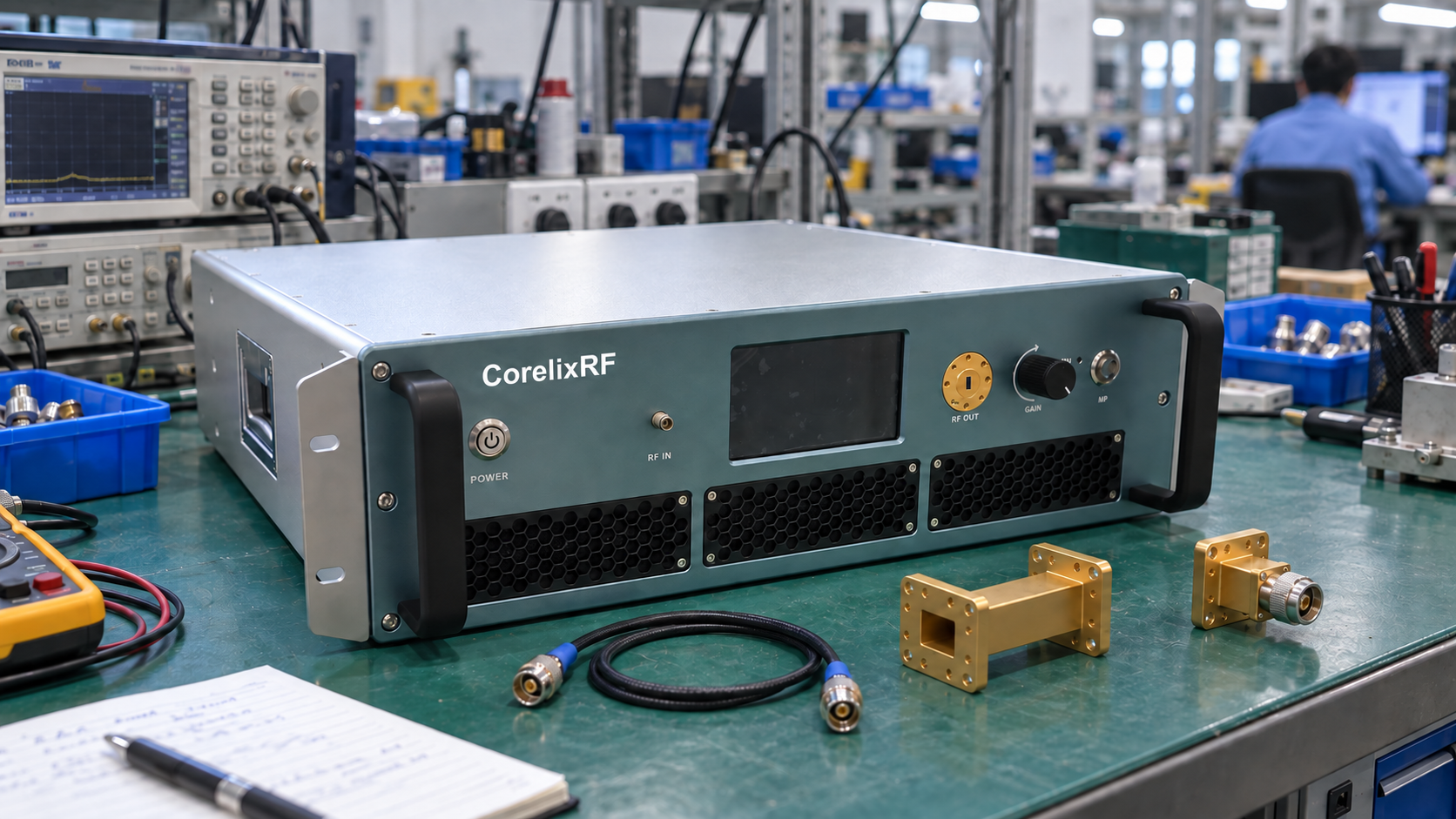
For mmWave power amplifiers, choose RF ports by checking the band, power, loss and space you need. Review both ends of each RF amplifier. A coaxial input and a waveguide output need different parts to connect them.
Start with the gear you already have: source cables, couplers, loads and test adapters. Before you compare microwave and mmWave amplifier platforms, draw each RF link. Include every part from source to load and test port.
1. Check Both Ports on mmWave Power Amplifiers
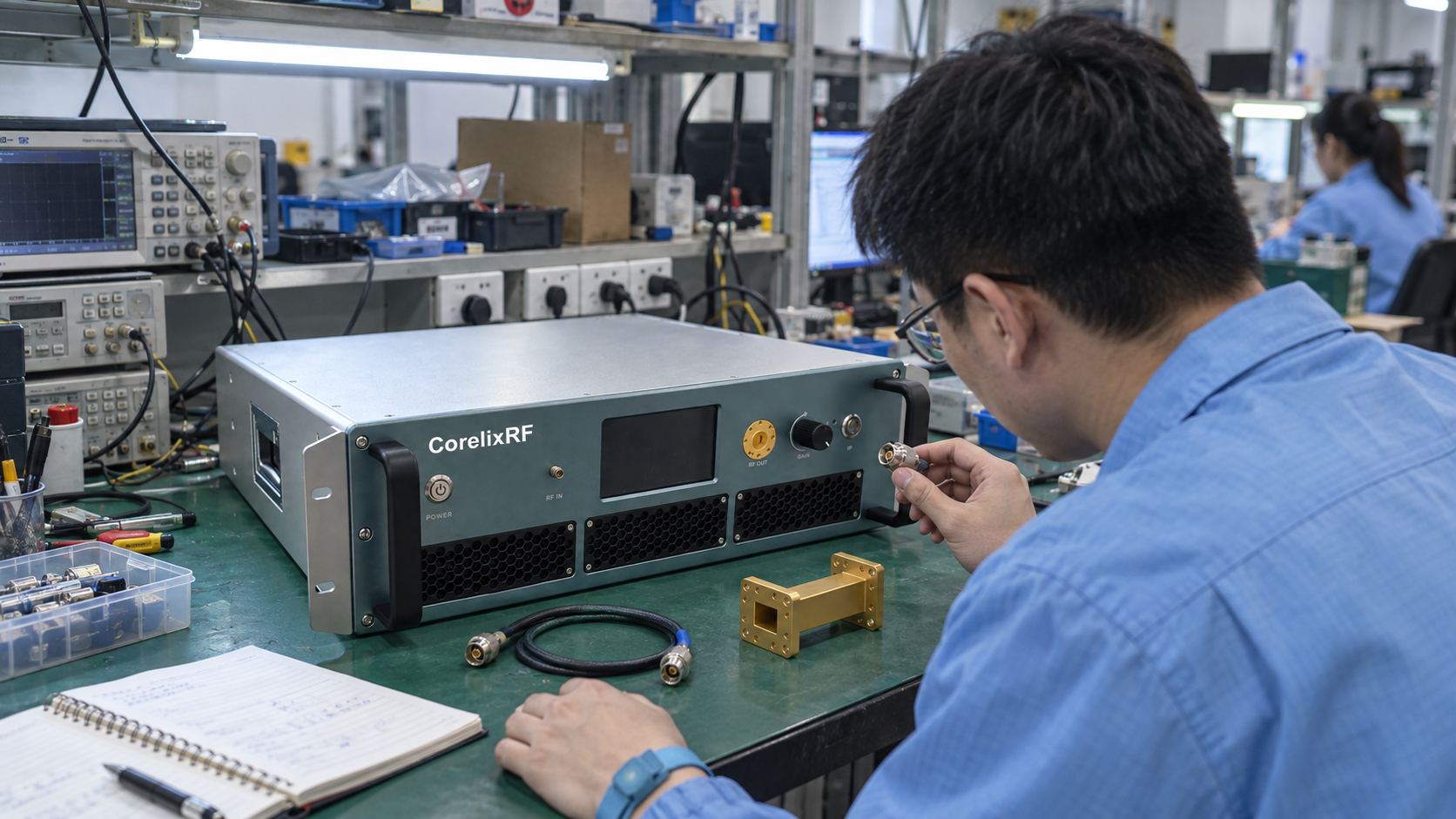
Check both RF ports on mmWave power amplifiers. The term “waveguide amplifier” alone leaves gaps. Does it mean one waveguide port or two? Which sizes does the model use, and where are those ports?
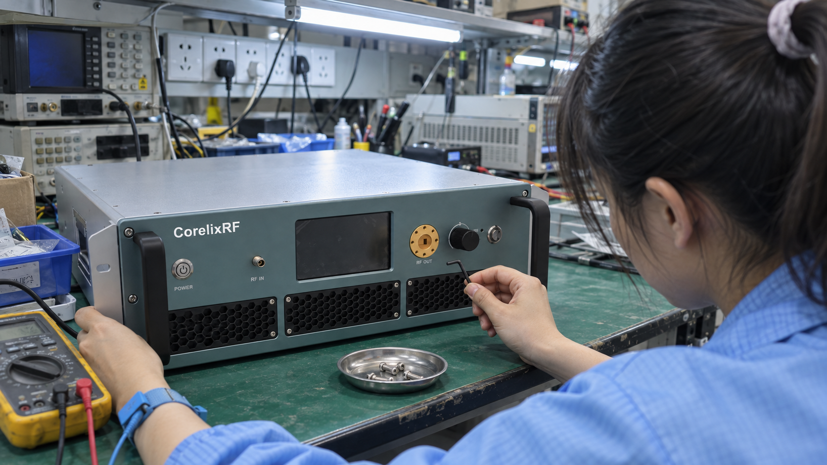
These two CorelixRF models show why both ports need a check:
| Model | Frequency range | RF input | RF output |
|---|---|---|---|
| CRF-PA-26500M40000M-40W | 26.5–40 GHz | 2.92 mm female | WR28 |
| CRF-PA-50000M75000M-5W | 50–75 GHz | WR15, front panel | WR15, front panel |
For the 2.92 mm input, check the plug on your source cable and its rated band. For the WR28 output, check the mating flange and waveguide parts. An adapter marked “microwave compatible” still needs a check at each end.
The 50–75 GHz WR15 platform uses waveguide at both RF ports. If your source has a coaxial output, add a suitable adapter to the input path. Then check its band and loss.
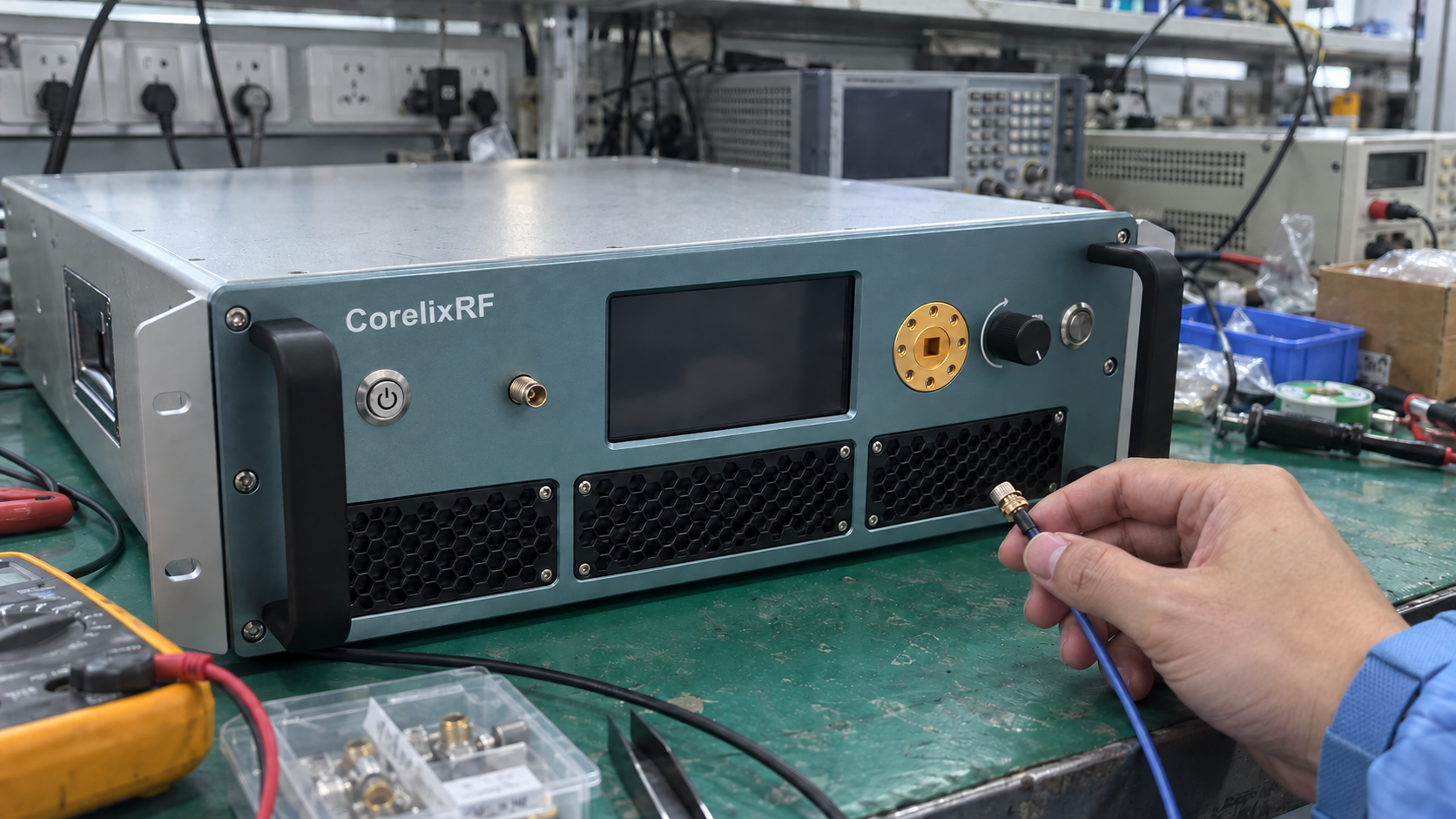
Record ports in a connection list:
- Signal source output → cable or adapter → amplifier input.
- Amplifier output → coupler, adapter or waveguide section → load.
- Measurement sampling point → attenuation, where required → receiver or power sensor.
Use exact part numbers when you have them. Keep the CorelixRF datasheets beside your list so you can check each model, port and drawing version.
2. Check the Band of Each RF Part
There is no single point where all RF designs must switch from coaxial cable to waveguide. The choice also depends on cable type, power and the parts you can use.
Check the rated band of each part, including adapters and calibration tools. Even if two parts fit, one may fall outside its rated band.
For example, suppose you need a sweep from 26.5 to 40 GHz. An adapter rated only to 33 GHz leaves a gap. You cannot claim full-band use from that rating. A new plug does not extend its rated band.
Use the same check for an 18–40 GHz amplifier. Every part must cover your test band. Otherwise, a waveguide section or load can limit the range you can test.
Compare both paths while you plan the layout:
| Decision | Coaxial path | Waveguide path |
|---|---|---|
| Frequency coverage | Check connector family and complete cable-assembly rating | Check specified operating band for each waveguide component |
| Routing | Check cable length, bend radius and connector access | Check section lengths, bends, flange orientation and supports |
| Loss | Obtain assembly loss across the required band | Obtain loss for sections, bends and adapters |
| Connections | Confirm connector type, gender and mating condition | Confirm waveguide size, flange details and alignment |
3. Check Power Limits and RF Path Loss
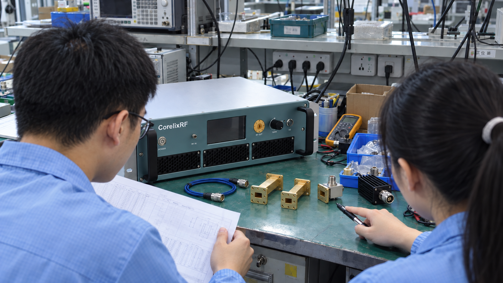
A part must meet both your band and power needs. An adapter may fit and cover the right band, yet have a power limit that is too low.
For each part in the output path, check its average power limit. For pulsed use, check peak power as well. Read the stated test conditions because heat, pulse width, duty cycle and load mismatch can change the limits.
When you compare mmWave power amplifiers, check how each output rating is defined. Saturated power, linear power and pulsed peak power refer to different conditions. Use the RF power amplifier specifications to match your working point before choosing output parts.
Check input and output parts on their own. A cable that works with a low-level source may not suit a high-power output.
Insertion loss also changes delivered power. For a simplified matched path:
P delivered = P entering × 10^(−L/10)
Here, L is path insertion loss in decibels.
For example, 20 W entering a path with 1 dB loss gives about 15.9 W at its far end. This is a calculated example, not a CorelixRF test result. It assumes matched ports. It leaves out added mismatch effects and measurement uncertainty.
If you need 20 W at the load, a “20 W amplifier” still leaves the path loss to resolve. State where you need that power. Then add up the loss between that point and the amp output.
For a sweep, use loss data across the band. When you change a cable or add an adapter, update the loss budget. Record the new part numbers and check whether you can still reach the power target.
4. Set the Measurement Reference Plane
Set a reference plane, which is the point where a reported RF value applies. It could be the amp output flange, the coaxial port of an adapter, or the load input.
For example, two power tests may use these points:
- Measurement A reports power at an amplifier’s output flange.
- Measurement B reports power after an adapter and connecting cable.
The path between those points may explain the gap in their readings. So keep each result tied to its test point before you compare them.
A single loss value does not fully correct every test. For example, a scalar power correction does not replace a calibrated S-parameter measurement.
Write down:
- The quantity being measured and its reference plane.
- Adapter, cable and coupler identities.
- Applicable calibration or correction data.
- Frequency range and operating power.
- Measurement uncertainty and acceptance limits.
Before you connect a receiver to a high-power output, plan how to sample and attenuate the signal. Check the power limit of each test port. An interface adapter must not serve as a protective attenuator unless its rating supports that use.
Our guide to amplifier S-parameter measurement explains calibration and test setup. For this port review, state where each result applies. Also list the parts whose effects remain in that result.
5. Check Flange Fit and Port Access
Check the physical fit while you choose RF parts. A port may meet the electrical limits but leave too little room to fit or remove the hardware.
The WR code identifies the waveguide size. You also need the flange drawing to check how the two faces mate. Compare bolt details and direction on both drawings.
For coaxial ports, record the type and whether each end is male or female. Leave room for the nut, wrench and cable bend. For waveguide, check bolt access, flange direction and support for attached parts.
A right-angle adapter may solve one space issue but cause another. Check its full size with nearby cables and panels in place. Use a drawing because a photo cannot confirm the fit.
Include the fitting instructions with your handover files. Follow the stated steps for each plug or flange. Torque values for one type may not apply to another.
Before you approve the layout, check access to each RF joint. Staff should be able to inspect, fit and remove it. Also add supports where heavy parts would otherwise strain an amp port.
6. Prepare an RFQ for mmWave Power Amplifiers
Send a connection drawing when you request mmWave power amplifiers. A simple block diagram can work if it shows both RF ports and each external part.
List the gear you already have and the parts you still need. For example, a fixed flange, power sensor or tight cable route may limit your choices.
Use this list to explain the RF interfaces you need:
| Item | Information to provide |
|---|---|
| Operating band | Start and stop frequencies, plus any excluded sub-bands |
| Power target | Required power and its reference plane |
| Signal conditions | CW or pulsed operation; pulse and duty conditions where applicable |
| Source connection | Output connector, available drive and existing cable details |
| Amplifier input | Required connector or waveguide interface |
| Amplifier output | Required connector or waveguide size and flange |
| Downstream path | Loads, couplers, cables, bends and adapters, with part numbers |
| Measurement setup | Sensor or receiver, sampling arrangement and calibration plane |
| Mechanical limits | Port direction, envelope drawing, cable routing and access |
| Supporting documents | Applicable datasheet revisions, interface drawings and acceptance requirements |
For projects in that band, use the 18–40 GHz RFQ checklist to cover the wider system needs. Attach your port list as well, so the model review includes plugs, flanges and test points.
Send CorelixRF your RF connection drawing and interface requirements, including the source connection, output load, operating band and required power reference plane.