
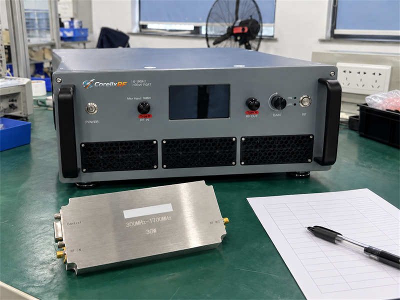
RF amplifier production testing should give each unit a clear release decision. Yet a fast test can miss a defect, while a poor connection can reject a good unit. Start with the product limits and fixed test conditions. Keep a record of each failed test and each rerun.
The method applies to module and system-level RF power amplifier platforms. Choose checks that fit the band, power, waveform, cooling, and agreed scope. The plan should say what to test, when to stop, and which records to ship with each unit.
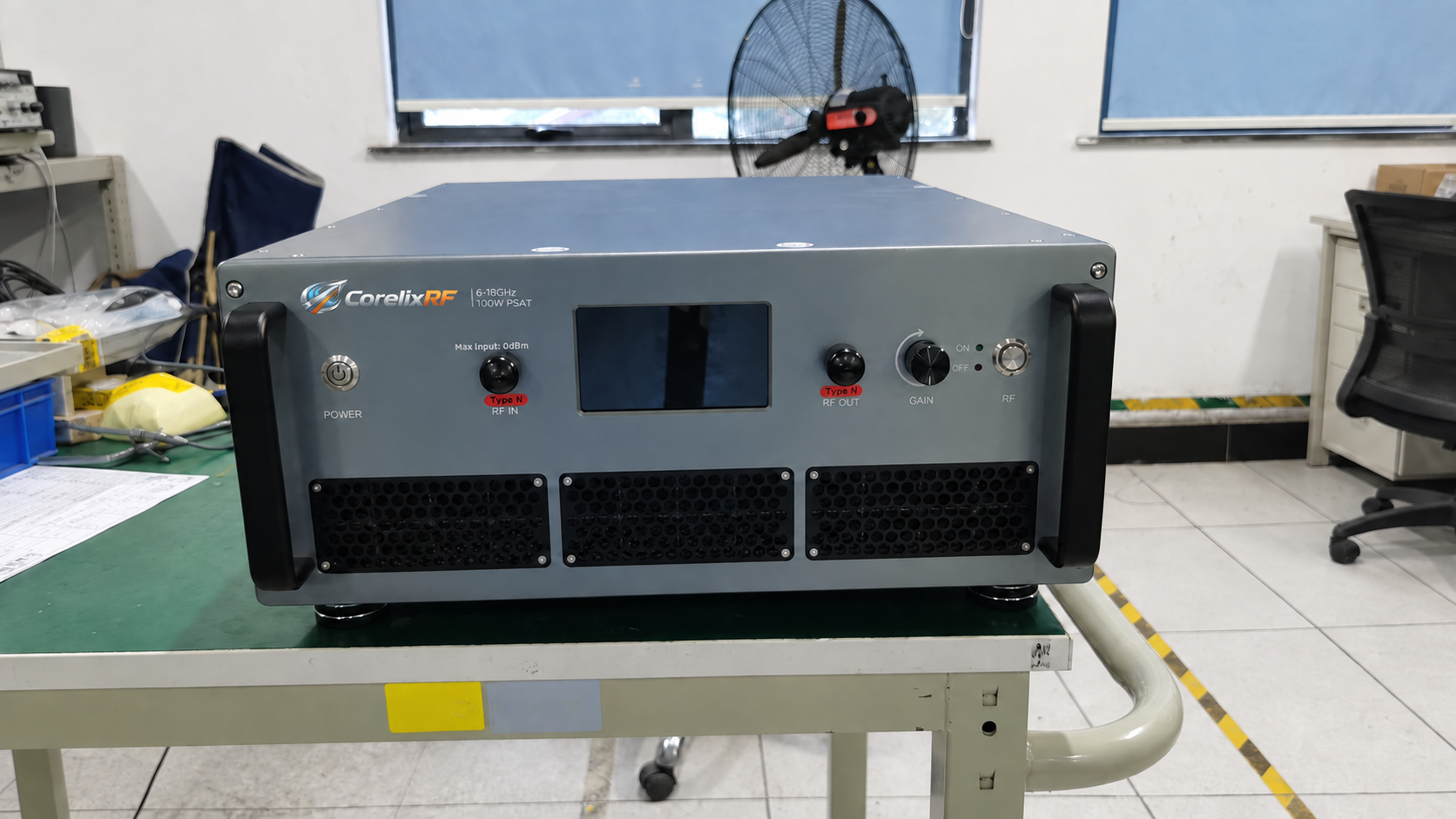
1. What Should RF Amplifier Production Testing Decide?
In RF amplifier production testing, each check needs a clear job. It may confirm a release limit, find a build fault, or flag a test bench issue. State how the result will guide the next step before adding a test.
Repeatability comes before speed. A good unit should not fail just because a new person or bench runs the test. At the same time, the line must meet its output target. Keep the build, setup, and test details that help explain each result.
Use four clear outcomes:
- Release: all required results meet the agreed decision rule.
- Hold: data are missing, conflict, or come from a faulty test bench.
- Rework: the team has found a fault it can fix through an approved repair plan.
- Reject: the unit fails its limits or cannot pass the approved rework steps.
| Test goal | Evidence to keep | Decision |
|---|---|---|
| Check basic function | Power-up, current, controls, alarms, and RF response | Continue or stop |
| Check RF output | Corrected values at set test points | Release, hold, or reject |
| Detect process shifts | Results by lot, station, fixture, and time | Find the source of drift |
| Check before shipment | Unit identity, limits, results, and final status | Approve shipment and review records |
If a test cannot change a decision, review its place in the plan. It may belong in design work or a planned audit instead.
2. How Does Production Testing Differ From Characterization and FAT?
Characterization maps how a design behaves. Engineers may vary frequency, drive power, supply voltage, temperature, load, and waveform. Those tests show margins and failure points. They also help the team choose which points to test on the line.
In contrast, RF amplifier production testing applies an agreed plan to each build. It tends to use fewer test points, fixed code, checked fixtures, and clear limits. Each unit should face the same release rule.
Factory acceptance testing, or FAT, helps the buyer decide whether to accept the goods. It may review line records, repeat agreed tests, or add checks that the buyer will witness. However, FAT cannot replace the controls used on the line.
Use the RF power amplifier acceptance testing method to set the needed power, gain, S-parameter, and thermal checks. Then agree on the test points and records for the chosen model.
The CorelixRF testing and documentation scope sets out the types of test, unit, inspection, and project records. Keep these roles clear in the RF amplifier production testing plan. One sample report does not prove that each shipped unit passed the same checks.
3. Which Checks Belong in RF Amplifier Production Testing?
No single test list fits every product. Base the plan on risk, likely faults, build steps, buyer needs, and the cost of a missed defect. A key release check may need to cover every unit even if it takes longer.
Start with low-risk checks before turning on RF power. Check the unit ID, look for damage, inspect the ports, and run the required continuity tests. Then check supply current, controls, interlocks, and alarms. Apply RF only with the rated load and cooling in place. Follow the approved plan for power, gain, spectrum, current, and protection checks.
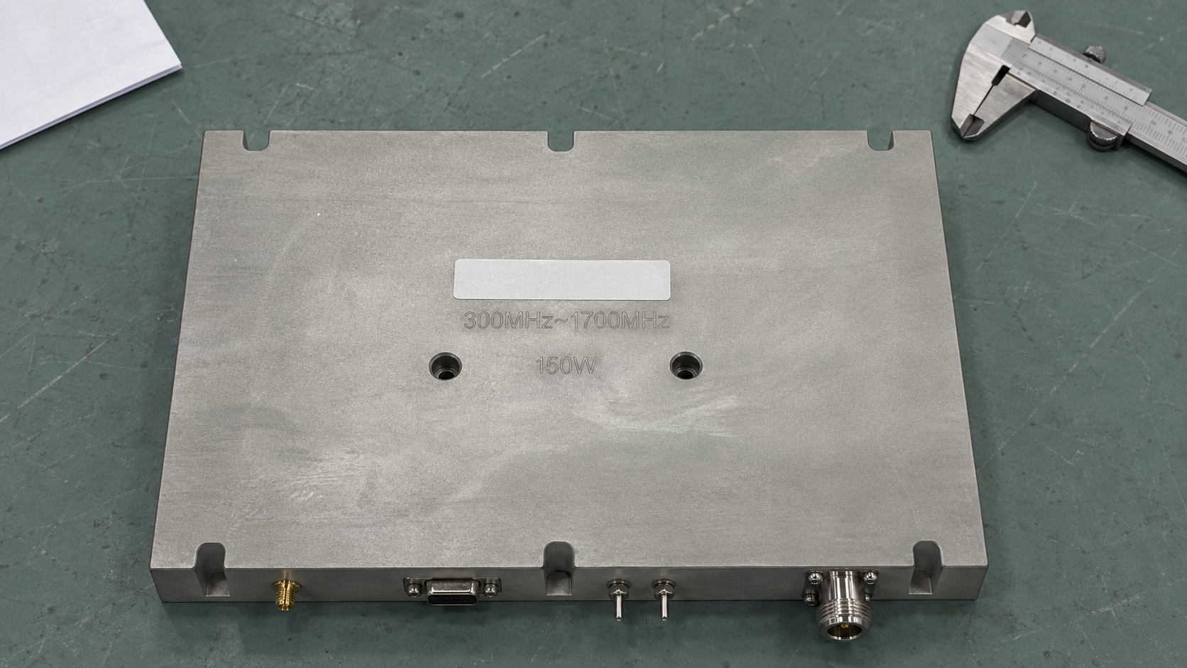
The RF amplifier power, gain, and thermal test methods explain the roles of basic electrical, CW, pulsed, and thermal checks. Use them to choose the test conditions each unit must pass.
Long heat soaks, dense sweeps, environmental tests, and tests that damage a unit may suit design qualification or planned samples. However, a contract can require some of these checks on every unit. Follow the control plan and customer agreement.
| Test item | Possible coverage | Fault or risk addressed | Record to keep |
|---|---|---|---|
| Identity and revision | Every unit | Wrong build or setup | Serial number and hardware/software revision |
| Supply and idle current | Every unit or a defined stage | Bias, assembly, or short-circuit fault | Voltage, current, and operating state |
| Power and gain | Key frequencies or full sweep | Low output, tuning error, or RF path fault | Input, output, correction, and frequency |
| Harmonics and spurs | Product-dependent | Nonlinearity, oscillation, or assembly fault | Spectrum settings, value, and limit |
| Controls and protection | Product-dependent | Failed interface or protection action | Command, condition, and response |
| Thermal or burn-in test | Every unit or agreed sampling | Early-life or thermal fault | Duration, load, cooling, and monitored values |
| Environmental stress | Often qualification or sampling | Mechanical or environmental weakness | Method, sample, condition, and outcome |
Set stop conditions before the run. For example, a current-limit failure should stop high-power RF testing. A load, airflow, interlock, or analyzer-protection fault should also block RF enable.
4. How Should You Design an RF Production Test Station?
Define the measurement reference plane before choosing instruments. Input power may mean power at the amplifier connector, after the input cable. Likewise, output power may mean power at the DUT, before the coupler or attenuator. Record each path correction and the frequency range it covers.
A high-power bench needs a source, DUT fixture, supply, cooling, directional sampling, rated load, and test gear. It also needs safety interlocks. Switches can save time spent changing cables. However, their loss, isolation, and repeatability affect the test. Track their version with the rest of the bench.
Separate three activities:
- Calibration links measured values to known references through a recorded chain.
- Verification checks that the full bench still meets its approved test state.
- Readiness checks check the load, airflow, fixture, attenuation, data links, and interlocks before a run.
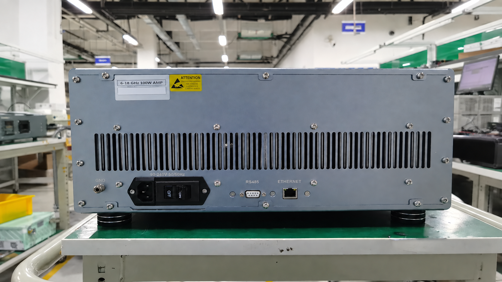
A calibration label alone does not make the final result traceable. Also keep the method, path corrections, uncertainty, gear status, and setup records. The CorelixRF RF test lab overview shows how the source, amplifier, load, test path, cooling, and records work together.
Stop if required calibration is out of date or a correction file does not match the active path. Also stop if an interlock is bypassed or the load and cooling cannot meet the test needs. Then review units tested since the last valid station check.
5. How Do You Correlate Stations and Control Drift?
Two benches can use the same gear and still disagree. Cables, fixtures, corrections, code, warm-up, heat, and repeated connections can all change a result. Compare the full test process under the same conditions.
Wideband units need close control of frequency-dependent loss. The wideband RF amplifier gain-flatness and calibration guide explains how path corrections and stable connections affect comparisons.
Use a stable reference unit or transfer standard. Record how to handle it and which test conditions to use. Run the same method, DUT state, frequencies, drive, cooling, and reference plane on each station. For RF amplifier production testing, compare each measured value on its own. One overall score can hide an error at a single frequency.
The reference unit checks the process; it does not replace instrument calibration. Do not retune it to make a changed station pass. Instead, keep a history of changes to the unit, bench, and connections.
| Symptom | Possible cause | Check | Next action |
|---|---|---|---|
| Constant offset across frequency | Path correction or power-reference difference | Compare correction files and reference planes | Hold the station until resolved |
| Error grows with frequency | Cable, coupler, fixture, or connector response | Sweep the path and inspect interfaces | Repair or recalibrate the affected path |
| Spread after reconnection | Connector wear, torque, or fixture repeatability | Repeat controlled connections | Repair the fixture or revise the method |
| Drift during a shift | Warm-up, temperature, load, or attenuator heating | Trend reference checks with time and temperature | Set recovery and impact-review rules |
| One software version disagrees | Changed settings, corrections, or calculations | Compare versioned raw data and setup | Roll back or validate the change |
Plot reference results against the approved warning and action limits. If a result crosses an action limit, stop the bench. Keep the data and find the last valid check. Then review all affected units under the quality plan.
6. How Can You Reduce Test Time Without Losing Coverage?
Measure where time goes before removing tests. Time each step: handling, connections, startup, warm-up, leveling, switching, settling, capture, maths, storage, and retest. A quick reading may still need a slow setup.
RF PA stations may use a power-servo loop to reach a target output. They can then check gain, spectrum, EVM, or adjacent-channel behavior at that point. Keep a valid test state where the next check can use it. This avoids repeated settling. Faster waveforms or hardware-timed steps may help, but only if the method and gear support them.
Improve RF amplifier production testing throughput in a controlled order:
- Avoid setting up the same gear, loading the same files, or sending the same calls twice.
- Group tests that share frequency, waveform, power, and routing.
- Where supported, wait for a measured stable state instead of a fixed delay.
- Capture data once and use that set for the approved results.
- Run separate tasks at the same time only after checks for isolation, heat, supply load, and data ownership.
- Remove or move a test only after a risk and coverage review.
Also track first-pass time separately from retest and fault-finding. A fast sequence with frequent false failures can reduce total output. Each change must keep the same test point, decision rule, and ability to measure the result.
7. How Should Limits, Guard Bands, and Uncertainty Work?
Keep the product specification, or spec, separate from the bench limit. The spec states what the unit must do. The bench limit uses the agreed decision rule to judge a measured result.
For a minimum value such as output power, the bench may need a stricter lower limit:
AL_min = LSL + g
For a maximum value such as a harmonic limit, the bench may need a stricter upper limit:
AL_max = USL – g
Here, g is the guard band. LSL and USL are the lower and upper spec limits. The size of g depends on uncertainty, process behavior, risk, and the agreed rule. Do not set it to a fixed share of the tolerance without a sound basis.
| Requirement | Spec limit | Possible internal rule | Risk addressed |
|---|---|---|---|
| Minimum value | At or above LSL | Accept at or above LSL + g | False pass near the lower limit |
| Maximum value | At or below USL | Accept at or below USL − g | False pass near the upper limit |
| Two-sided requirement | Between LSL and USL | Use a defined inner interval | Wrong pass/fail calls near either limit |
| Data only | No release limit | Record and trend without pass/fail | Missed process shifts |
JCGM 106 describes guard bands as a means of controlling the risk of wrong conformity decisions. Both the process and the test system affect that risk. The accuracy of one instrument does not define the uncertainty of the whole test.
For RF amplifier production testing, record the limits, uncertainty treatment, rounding rule, and action for borderline results. Agree on them before testing starts.
8. What Should Happen When a Unit Fails?
RF amplifier production testing must keep the first failed result. Save the raw and corrected values, limit, bench state, fault code, and test step. Otherwise, a later passing run can hide evidence about the product or station.
Set a clear next step for each type of failure:
- Connection or fixture check: use when the signs point to an open, poor contact, wrong adapter, or fixture fault.
- Controlled rerun: follow a written reason, rerun limit, and required state reset.
- Station hold: use when reference checks, calibration, interlocks, corrections, or several units indicate a station problem.
- Rework: follow an approved instruction and record parts, tuning, technician, and revision.
- Engineering review: use for unclear faults, results near a limit, repeat failures, or tests outside the approved plan.
Avoid “test until pass.” Extra warm-up, new attenuation, tuning, or more cable changes can yield a pass in a new test state. If a change is valid, record it and keep both results.
For reflected-power faults or protection events, check thresholds, protective action, and recovery under project-defined conditions. Use the RF amplifier VSWR protection and FAT testing guide when defining that evidence.
After rework, repeat the affected tests and all earlier checks needed to run the unit safely. Then record why the unit returned to production and who approved release.
9. Which RF Amplifier Production Testing Records Should You Keep?
Each test result needs a traceable chain. Link it to the DUT, method, bench, references, corrections, limits, and test time. One calibration label covers only part of that chain.
| Record field | Level | Purpose | Typical owner |
|---|---|---|---|
| Unit identity and revision | Unit | Link data to delivered hardware | Manufacturing or quality |
| Work order, lot, and material batch | Unit and batch | Trace changes in parts or process | Manufacturing |
| Test method and code version | Run | Repeat the steps and pass/fail rules | Test engineering |
| Station, fixture, and path ID | Run | Find bench-related changes | Test engineering |
| Instrument IDs and calibration status | Run | Support measurement traceability | Metrology or quality |
| Operator or automated cell ID | Run | Review how the test ran | Operations |
| Environment and cooling state | Run or test point | Explain temperature effects | Test engineering |
| Raw and corrected values | Test point | Check maths and corrections | Test system |
| Limits and decision-rule revision | Test point | Recheck the pass/fail rule | Quality team |
| Failure, retest, and rework history | Unit | Preserve the full release history | Quality |
Store units and reference planes with the values. For example, “power” could mean generator output, DUT input, or corrected DUT output. Also record gain state, waveform, pulse conditions, and thermal state where relevant.
Use lot and station trends together. A group of units may shift because of material, assembly, tuning, or bias changes. In contrast, a change on one station may point to its fixture, cable, instrument, or software.
Build delivery records from verified RF amplifier production testing data. Include the build, test, inspection and goods-receipt records relevant to the buyer. Use the buyer’s RF amplifier test-data checklist to agree on the requested evidence. Keep unrelated internal data out of the buyer’s report.
10. What Should Buyers Ask Suppliers About Production Test?
Ask how the supplier plans RF amplifier production testing from the product spec. Request the controls behind a sample report, then check them against the project needs.
- Which checks cover every unit, sampled batches, or qualification only?
- Which frequencies, waveforms, loads, cooling conditions, and reference planes apply?
- How are stations calibrated, verified, correlated, and checked during a shift?
- How do uncertainty and guard bands affect pass/fail decisions?
- What stops production when a station or reference check fails?
- Which retests are allowed, and does the record retain the first failure?
- How are software, corrections, fixtures, and limits version-controlled?
- Which unit and batch records can accompany the order?
- Who records and approves rework, deviations, and engineering decisions?
- How will both teams compare incoming checks with factory results?
Put required evidence into the RF amplifier RFQ checklist or quality agreement. Agree on the format, unit IDs, test points, decision rule, and handling of deviations before the quote and release to build. That gives both teams a clear basis for accepting the delivered units.
RF Amplifier Production Testing FAQ
Must every RF amplifier parameter be tested on every unit?
No. Base coverage on risk, process capability, the contract, and the cost of a missed defect. Long tests or those that damage a unit may suit qualification or samples. However, key release checks may need to cover every unit.
What is a production reference unit?
It is a stable unit or standard used to compare benches or track drift. Record its build, history, handling, storage, and expected results. It checks the process but does not replace instrument calibration.
How often should an RF production test station be calibrated?
Follow the metrology plan and the needs of each instrument. Set the timing from use, test conditions, drift history, and risk. Also plan bench verification and pre-run checks. A valid calibration date cannot rule out faults in cables, fixtures, corrections, or code.
Is a guard band the same as a product tolerance?
No. Tolerance states the range that a good product must meet. A guard band narrows the test pass range to manage risk near a limit. Record its size and use in the decision rule.
Can FAT replace production testing?
No. FAT may review records or repeat agreed checks, but it cannot replace the controls for each unit on the line. Where both plans cover the same tests, use the same build, conditions, units, and pass rules.
Before asking for a quote, list the band, power, mode, key checks, unit records, and release rule. Then ask the CorelixRF RF engineering team to review the relevant platform and available test-documentation scope.