

Buying an RF power amplifier is not only a frequency-and-wattage decision. Whether the project uses a rack-mounted solid state power amplifier or a compact RF amplifier module, a datasheet can confirm band, output power, gain, connector type and mechanical format, but it does not always prove how a specific unit behaves across the full range.
The answer depends on the application, but evidence should connect the amplifier specification to the real RF chain. A buyer evaluating a standard RF amplifier platform, a modified module or a custom RF power amplifier should request measured records that show power, gain, spectrum, protection behavior, thermal condition and test setup.
Throughout this article, any CorelixRF technical-documentation support, application review, customization path, or test-data recommendation is subject to project review, the supplied product configuration, and the project’s requirements.
Why RF Power Amplifier Test Data Matters
RF amplifier performance is strongly tied to measurement conditions. Output power can vary with frequency, drive level, duty cycle, waveform, temperature, load match, connector reference plane and cable loss. A 100 W high power RF amplifier claim or a 50 dB gain value is useful only when the buyer understands how it was measured.
This is especially important for broadband and high-power products. A broadband RF amplifier may need closer review near band edges. A pulsed RF amplifier may require pulse width, duty cycle and PRF evidence rather than CW-only data. An EMC amplifier may need power margin data tied to radiated-immunity assumptions. For these cases, RF testing and validation evidence is part of the buying decision.
Start with the Test Setup
Before reviewing numbers, request the setup context. The test report should identify the model, serial number or unit identifier, test date, frequency range, operating mode, input drive condition, supply voltage, load condition and measurement point. It should also state whether the reported power is measured at the amplifier output connector, after an adapter, after a coupler, or at another reference plane.
This context prevents false comparisons. Two reports can show different output power because one includes cable loss and the other reports at the amplifier port. A spectrum plot can hide or reveal spurious behavior depending on span and output level.
Output Power Across the Operating Band
The first required evidence is measured output power across the frequency band. For a CW radio frequency power amplifier, request rated or saturated output power data at representative frequency points, including band edges. For a pulsed amplifier, request pulse output power data with the stated pulse width and duty cycle. If the system will use a specific waveform, sweep mode, hopping profile or modulation type, include that in the inquiry.
Buyers should avoid accepting only a single center-frequency value for a wideband RF power amplifier. Full-band behavior matters for antenna drive, chamber margin, system acceptance and test repeatability.
Gain, Flatness and Compression Evidence
Small-signal gain and gain flatness help engineers predict drive level and frequency-dependent output behavior. Ask for measured gain across the band and compare it with source power, attenuation and safety margin. Gain flatness is especially important in swept-frequency testing, broadband interference simulation and EMC work.
Compression evidence is useful when the system must avoid nonlinear behavior. Request P1dB, Psat or another defined compression point only when that value is relevant and supported by the supplier’s test method. Do not mix small-signal gain, P1dB, saturated output power and usable linear output as if they are the same thing. Each value answers a different engineering question.
Harmonics, Spurious and Spectrum Records
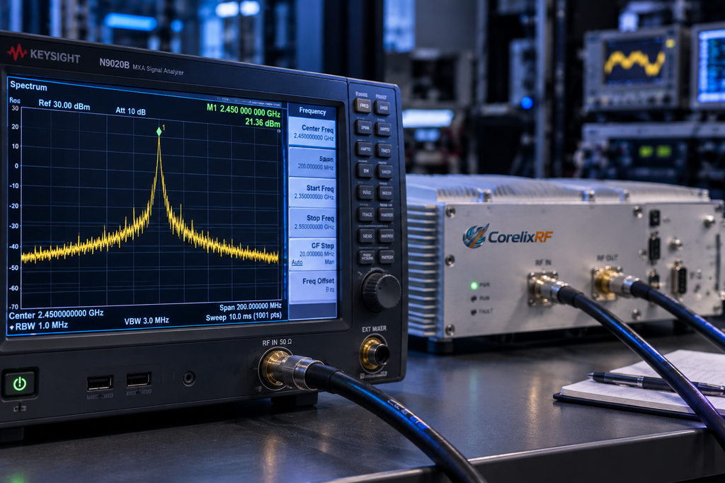
Power alone does not show whether the amplifier is usable. Request harmonic and spurious data at relevant output levels. For many RF test racks, spectrum behavior affects filter selection, receiver protection and interpretation of test results. If the amplifier is used in a sensitive measurement environment, ask for spectrum plots or tabulated data that show setup conditions clearly.
The required level of detail depends on the project. A lab driver amplifier may need enough data to protect instruments. A communication, EMC or aerospace-control project may need closer review of unwanted emissions, gain stability and interface behavior.
VSWR, Protection and Thermal Data
RF power amplifiers often operate with real loads, cables, antennas and fixtures that are not perfectly matched. Buyers should ask how mismatch and reflected power are monitored or protected. Useful records may include VSWR alarm thresholds, reverse-power detection availability, protection response, alarm output, recovery behavior and any controlled condition used to validate the function.
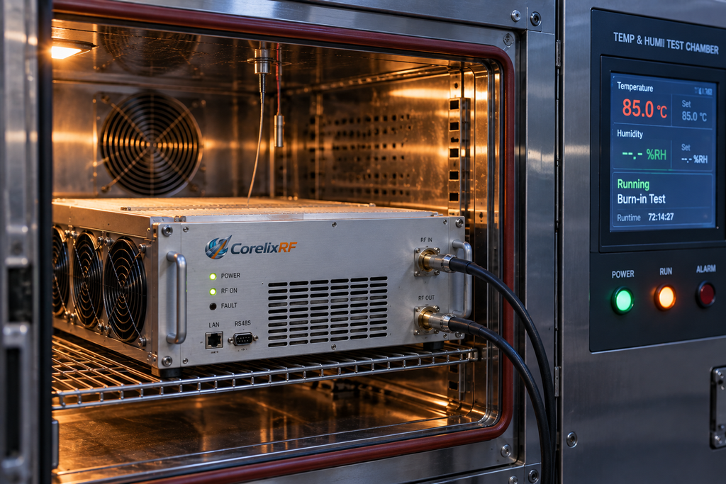
Thermal behavior also needs review. A cold-start power result may not reflect sustained operation. Ask whether the unit was tested after warm-up, whether output and gain were recorded after thermal stabilization, and whether burn-in or aging records are available for the product class. For high-power systems, also request cooling requirements, inlet temperature assumptions, rack airflow direction and over-temperature alarm behavior. This helps decide whether a broadband EMC amplifier, pulsed platform, module or rack-mounted system is the right starting point.
Practical RF Amplifier Test Data Checklist
For most technical purchases, request these records before approval:
- Model, configuration and unit identifier.
- Frequency range and measured output power across representative points.
- Gain and gain flatness data across the operating band.
- Input drive condition and compression definitions where applicable.
- Harmonics, spurious or spectrum data at relevant output levels.
- VSWR, reflected-power, overdrive, over-voltage and over-temperature protection description.
- Thermal condition, cooling method, burn-in or stability evidence.
- RF connector, control interface, supply, mechanical drawing and reference-plane notes.
- Test setup context and calibration assumptions.
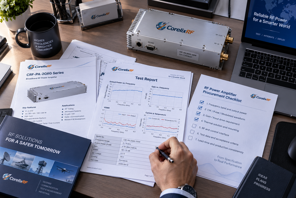
- Required document package for internal approval.
This checklist aligns engineering, purchasing and supplier communication. When the required evidence is known before quotation, the project is less likely to stall during sample review or incoming inspection.
How CorelixRF Buyers Should Use This Guide
If you are reviewing an RF power amp for a new system, start with the product family and build the evidence request around the actual operating condition. Compare the required frequency and power against CorelixRF RF amplifier platforms. If the project needs a non-standard band, interface, mechanical form factor, control method or documentation package, route the inquiry through custom review.
Provide frequency range, output power, CW or pulsed mode, waveform or duty cycle, gain expectation, connector preference, load condition, supply and cooling constraints, control interface, quantity, project stage and document needs. With those inputs, CorelixRF can identify what test data should support the decision.
FAQ
What RF power amplifier test data should a buyer request first?
Start with measured output power, gain flatness, input drive condition, harmonics or spurious evidence, and the test setup reference plane.
Is a datasheet enough for technical approval?
A datasheet is necessary, but it is often not enough for final approval. Technical buyers should also request unit-level or configuration-specific test data when output power, gain, thermal behavior, protection or documentation will affect system integration.
Why does the reference plane matter in RF amplifier testing?
The reference plane defines where the measurement is made. Power measured at the amplifier output connector is not the same as power measured after cables, adapters, couplers or waveguide transitions.
Should every buyer request P1dB and Psat data?
Not always. P1dB and Psat are useful when compression or saturated output behavior matters, but they must be defined by test method and operating condition.
Can CorelixRF provide project-specific test records?
CorelixRF can review test data and documentation needs by project requirement, including output power, gain, VSWR, spectrum, burn-in, inspection and acceptance records where applicable.