
A common RFQ starts with a sentence like this: “We need a 100 W RF power amplifier from 2 GHz to 6 GHz.” It sounds specific enough to begin sourcing, but an engineer reviewing the request will immediately see the missing pieces. What waveform is being amplified? Is 100 W required at the amplifier output connector, at the antenna, or at the device under test? Will the amplifier run continuously, pulse at a low duty cycle, or follow a swept test profile? Is the load predictable, or can reflected power become part of normal operation?
This is why learning how to select an RF power amplifier is not mainly about comparing catalog wattage. The better process is to translate the application into a requirement that a supplier can design, quote and support. The final choice may be a standard RF amplifier platform, a modified unit, or a custom RF amplifier. The right path becomes clearer when the requirement describes the real system instead of only the desired label.
Throughout this article, any CorelixRF technical-documentation support, application review, customization path, or test-data recommendation is subject to project review, the supplied product configuration, and the project’s requirements.
Begin with the Job the Amplifier Must Do
The first question is not which amplifier looks strongest on a datasheet. It is what the amplifier has to accomplish inside the system. A radio frequency power amplifier used for a lab bench may be selected very differently from one used inside an automated test system, EMC setup, radar simulator, communication link or fielded subsystem.
For example, a broadband RF amplifier may be chosen because one platform needs to cover multiple bands without changing hardware. In another project, a narrower amplifier may be better because the system needs cleaner behavior at one operating range. A high power RF amplifier may be necessary when cable loss, coupling loss or antenna mismatch reduces delivered power. In a compact embedded product, an RF amplifier module may be the correct starting point because the buyer already owns the enclosure and thermal design.
The selection becomes easier when the use case is stated in plain engineering terms. Is the amplifier generating test field strength? Driving a device under test? Extending a signal generator? Feeding an antenna? Replacing an older tube-based source with a solid state power amplifier? Each answer changes which risks deserve attention.
Turn the RFQ into Operating Conditions
An incomplete RFQ usually names frequency and output power. A usable RFQ also describes the operating condition behind those numbers.
Frequency should be treated as an operating range, not just a headline. A 2-6 GHz request may need flat performance across the entire band, or it may only need full output at a few points. A wideband RF power amplifier has to be judged by what happens near the band edges, during sweeps and under the requested drive level. If the system actually operates at a handful of fixed channels, the buyer may not need to pay for performance that the project will never use.
Power also needs a reference point. A request for 100 W can mean rated saturated power, usable linear power, pulse power, or delivered power after cables and fixtures. These are not interchangeable. If the system needs 100 W at the load after a long cable run, the amplifier output requirement may be higher. If the signal must stay linear, a saturated power rating may be the wrong comparison point.
The waveform completes the picture. CW operation, pulsed operation, modulated signals and swept-frequency tests create different thermal and linearity demands. Duty cycle, pulse width, crest factor and allowed compression can move a project from a standard product to a modified configuration.

Check Whether the Source Can Actually Drive It
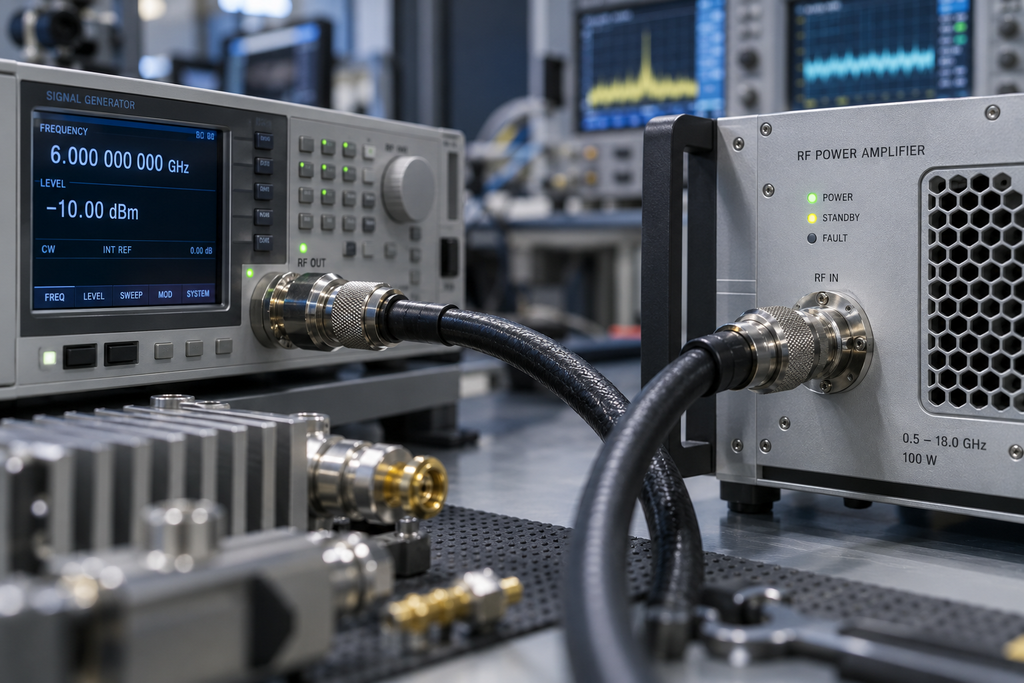
Many selection mistakes appear only after the amplifier is connected to the signal source. The amplifier may be rated correctly, but the source may not provide enough input power to reach output. Or the source may overdrive the amplifier when the gain is high, causing distortion, shutdown or measurement confusion.
This is why gain should be reviewed as part of the system chain. The buyer should know the available source power, expected losses before the amplifier input and whether an external driver stage is acceptable. In a swept or broadband system, gain flatness matters because available output can change across frequency.
This part of the review is simple but often neglected. A supplier can recommend a better configuration when the RFQ includes source type, available drive power, expected input level range and whether automatic level control is handled by the host system or by the amplifier.
Decide Who Owns Integration
The physical format of the amplifier is not a packaging afterthought. It defines who is responsible for cooling, control wiring, protection handling, maintenance access and system-level reliability.
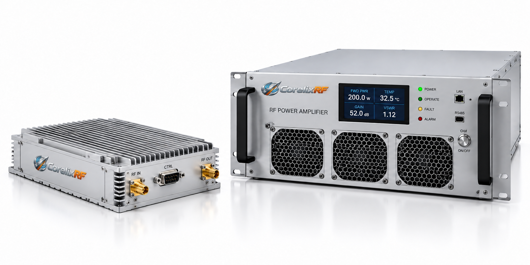
An RF amplifier module can be efficient and compact, but it usually expects the buyer to provide heat sinking, airflow, DC power, mechanical mounting and host-level monitoring. A rack-mount solid state power amplifier may be easier to deploy because AC power, cooling, front-panel status and remote control are already integrated. A custom subsystem may be needed when the amplifier must fit a fixed envelope, use a specific interface, support unusual duty cycles or survive harsh installation constraints.
This decision should be made early. If the buyer wants a module but does not yet have a thermal design, the project may slow down during integration. If the buyer chooses a complete rack system but later discovers a cabinet airflow conflict, the RF performance may be correct while the installation still fails. The best amplifier is the one the system can actually support.
Review Control and Fault Behavior Before Hardware Is Ordered
For many applications, the amplifier is not a standalone box. It is part of a controlled system. That means interface and protection behavior can be as important as gain and power.
A test bench may only need manual control. An automated system may need LAN, RS485, CAN, GPIB or discrete I/O. A field system may require remote status, interlock logic and predictable recovery after a fault. Common monitoring points include forward power, reflected power, temperature, current, voltage, gain state and alarm history.
Fault behavior should be described before the purchase order. What should the amplifier do during high VSWR? Should it fold back, shut down, alarm only, or recover automatically? What happens if input drive is too high? Does the host system need a fault output before RF is disabled? These questions prevent mismatches between the amplifier design and the control architecture.
Bring the Supplier into the Review Early
Once the operating conditions are clear, the buyer should bring the supplier into the review before the requirement becomes locked. This is where practical trade-offs often appear. A slightly different band split may reduce cost. A different enclosure may simplify cooling. A revised interface may avoid custom firmware. A realistic source drive level may remove the need for an extra driver stage.
This discussion is most useful when the supplier can see both the fixed constraints and the flexible ones. Frequency range, output power at the load, waveform and available space may be fixed. Connector position, interface type, cooling method or reporting format may still be negotiable. Separating those two groups helps the supplier recommend a platform instead of guessing around hidden limits.
The goal is to avoid a quote that looks correct but carries an integration problem into the next stage. A good selection conversation should end with a clear amplifier type, the assumptions behind it and the remaining engineering items that must be confirmed before order placement.
Choose Standard, Modified or Custom Without Guesswork
A standard amplifier is usually the best choice when the frequency range, output power, gain, cooling, connector, control method and documentation already fit the project. It is faster, lower risk and easier to support.
A modified platform is useful when the RF core is close but the project needs changes around the edges. Common changes include connector layout, control interface, monitoring points, enclosure details, interlock behavior or documentation format.
A custom RF power amplifier becomes the better option when the operating requirement cannot be covered cleanly by an existing platform. That may involve unusual bandwidth, pulse behavior, mechanical envelope, environmental conditions, integrated switching, control architecture or a system-level requirement that spans more than the amplifier itself.
The important point is that custom should not be used as a vague label for uncertainty. It should be the conclusion of an engineering review: standard does not fit, modification is not enough, and the cost of custom work is justified by the system requirement.
A Practical Selection Sequence
An efficient review can be run in this order. First, define the application and operating mode. Second, confirm frequency range and whether performance must be continuous across the band. Third, define the required output power at the correct reference point. Fourth, check source drive and required gain. Fifth, decide module, rack or subsystem format based on integration ownership. Sixth, define cooling, power supply and mechanical limits. Seventh, specify control, monitoring and protection behavior. Finally, request the level of test evidence that matches project risk.
This sequence keeps the discussion practical. It also helps suppliers avoid quoting a part that meets a table line but fails the installation.

What to Send CorelixRF
For a fast review, send the frequency range, required power and where that power is measured, waveform, CW or pulsed mode, duty cycle, source drive level, load condition, connector preference, cooling constraints, mechanical envelope, control interface, monitoring needs, protection expectations, quantity, project stage and required documentation.
With that information, CorelixRF can compare the requirement against existing RF power amplifier platforms, evaluate whether a modified configuration is enough, or recommend a custom path. If the project is still being defined, CorelixRF can also help identify which requirements are fixed and which ones still need engineering review.
FAQ
What information is needed to select an RF power amplifier?
At minimum, provide frequency range, output power, operating mode, waveform, input drive, load condition, cooling limits, mechanical format, control needs and documentation requirements.
Is frequency and wattage enough for RF amplifier selection?
No. Frequency and wattage are useful first filters, but they do not define delivered power, linearity, duty cycle, thermal load, interface behavior or integration limits.
When should I choose a broadband RF amplifier?
Choose a broadband RF amplifier when the system needs continuous coverage, swept operation or multiple operating bands in one amplifier platform.
When is an RF amplifier module the right choice?
An RF amplifier module is a good fit when the buyer can provide enclosure design, heat sinking, airflow, power supply integration and host-side monitoring.
Can CorelixRF help before the requirement is fully finalized?
Yes. CorelixRF can review early frequency, power, waveform, cooling, interface and documentation assumptions, then recommend a standard platform, modified configuration or custom RF power amplifier.