
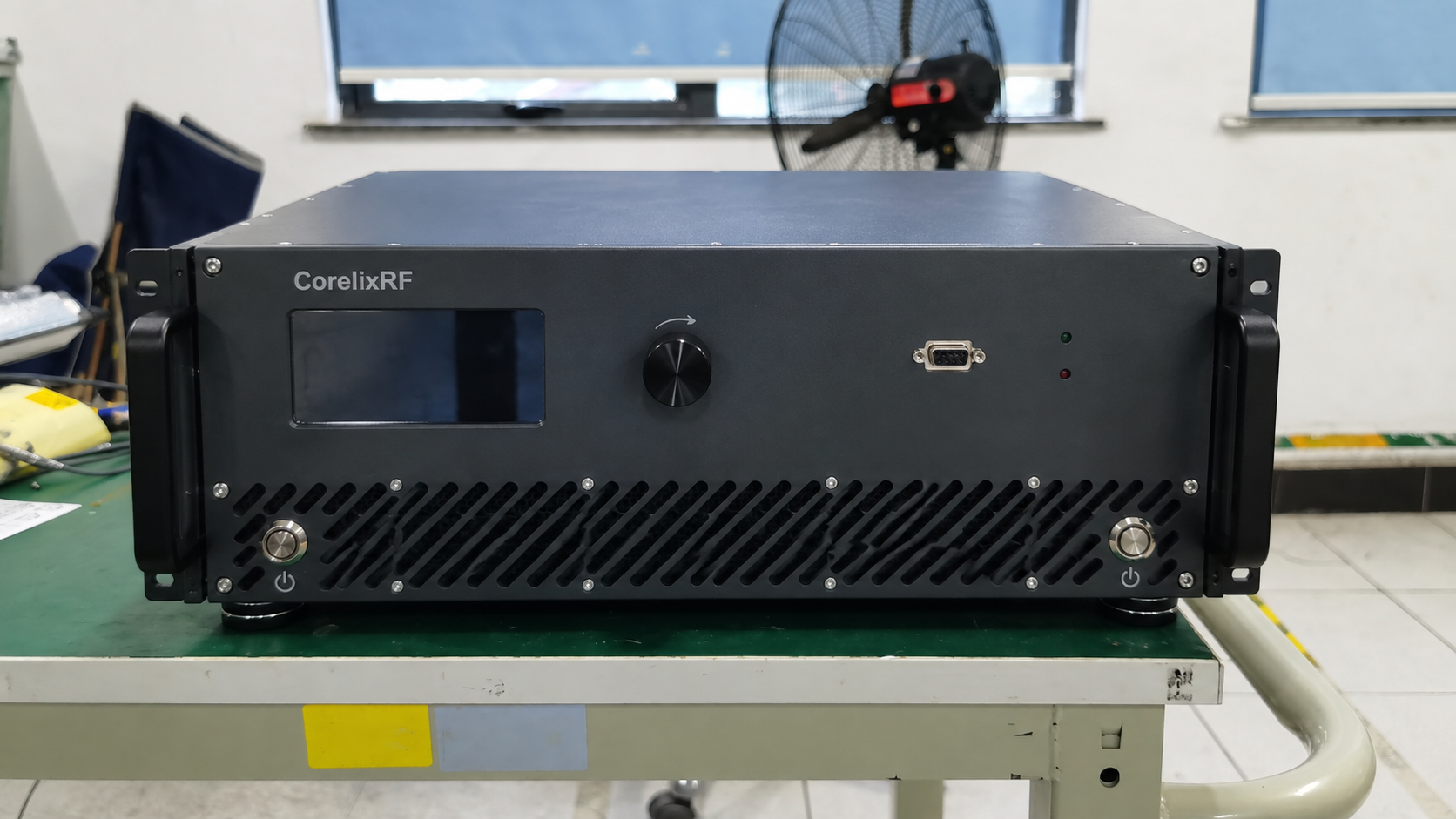
A GaN vs GaAs RF amplifier choice starts with your signal and the output it needs. Set the band, waveform and distortion limit. Then compare models under those conditions. GaN can suit a high power target. A GaAs design may already meet the task. Before you choose, check the whole unit’s supply, cooling and RF ports.
1. What Changes in a GaN vs GaAs RF Amplifier?
Device properties and circuit design
GaN means gallium nitride; GaAs means gallium arsenide. These materials give RF designers different options. GaN has a higher breakdown field. This gives designers scope for higher device voltages and power density. GaAs also has uses at microwave frequencies. These include driver stages and designs that reach their power target at lower device voltages.
If you need high RF output, GaN may be worth a closer look. However, keep a proven GaAs design on your list if it meets your gain, power and signal quality needs. A change of material can mean more work on the rest of your system.
Both types still rely on sound circuit design. Matching networks, bias, packaging, power combining and heat flow affect the result. As a result, two GaN models can give different results with the same signal. So the material label alone cannot tell you which one will fit.
Check the whole unit
When buying RF power amplifiers, write down the input signal and output you need. Also state the supply and cooling you can provide. A bare transistor’s data does not cover the whole unit. You still need facts about its drivers, power conversion and fans.
| Selection question | What technology helps explain | Evidence needed from a candidate |
|---|---|---|
| Can it deliver enough RF output? | Device voltage and power-density options | Output specification across the required band |
| Can it cover the signal? | Available devices and circuit approaches | Operating range and signal-bandwidth performance |
| Will it preserve signal quality? | Design options for gain and output stages | Distortion results under specified conditions |
| Will it fit the system? | Some electrical and thermal design constraints | Complete-unit supply, cooling and interface requirements |
Use each supplier’s data to fill the gaps. If a required value has no stated test conditions, ask for them before you compare offers.
2. How Does a GaN vs GaAs Choice Affect Band and Power?
Operating range and usable output
An amplifier’s tuning range and your signal’s bandwidth are different things. For example, a unit may tune over a broad band while your signal fills only part of that band at once. The tuning range alone does not prove that every wideband signal will meet your distortion limit.
Check what each power figure means:
- Rated output is the output stated under a supplier’s defined conditions. Ask what those conditions are.
- Psat is saturated output power under stated test conditions.
- P1dB marks output at the defined 1 dB gain compression point.
- Usable modulated output meets your signal’s distortion limits at a stated average or peak power.
A “100 W amplifier” label leaves room for doubt. Does it mean saturated power, continuous output, or average power that meets an EVM limit? State which one you need in your RFQ. Suppliers can then quote against the same need.
Also state whether you use CW, a continuously modulated signal or pulses. For pulses, give pulse width, repetition rate and duty cycle. Then add the thermal conditions and required run time. With these details, a supplier can assess the duty you expect the unit to handle.
A 6–18 GHz, 100 W GaN example
Our 28 V build in CorelixRF’s 6–18 GHz amplifier family is rated at 100 W output. Its own datasheet states that it uses GaN and covers 6–18 GHz.
That rating does not prove 100 W average output for your modulated signal. Nor does it give an EVM result, an ACLR result or a fixed back-off allowance. If you need that output, ask for data for your waveform and limits.
Ask for results at the points you plan to use, including band edges. Also record the supply and housing beside the model name. Similar names can refer to different builds.
3. How Do GaN vs GaAs Linearity and Efficiency Compare?
GaN vs GaAs under the same test conditions
Compare how much power each model delivers within the same signal quality limit. For example, your signal may be wideband with a high peak-to-average power ratio. A saturated CW test does not prove how a unit handles that signal.
Choose a metric that fits your task. EVM measures modulation accuracy under stated test conditions. ACLR measures leakage into adjacent channels. For intermodulation tests, define the signals and tone conditions. However, passing one test does not mean a unit will pass the others.
If a report uses digital predistortion, note that fact. A system without it needs results for that mode. Also record source quality and the test path, since both can affect what the test shows.
| Comparison field | Information to record for both candidates |
|---|---|
| Frequency | Carrier or test frequencies and required band coverage |
| Signal | Waveform, occupied bandwidth and peak-to-average ratio |
| Output | Average or peak value, power definition and reference plane |
| Distortion | Applicable limits, measurement settings and linearization conditions |
| Temperature | Ambient or baseplate condition, cooling and test duration |
| Supply | Applied input supply and relevant operating configuration |
| Efficiency | Power measurements, calculation boundary and operating point |
Use this sheet for the GaN vs GaAs comparison. Hold the test conditions fixed, then compare output within your allowed distortion.
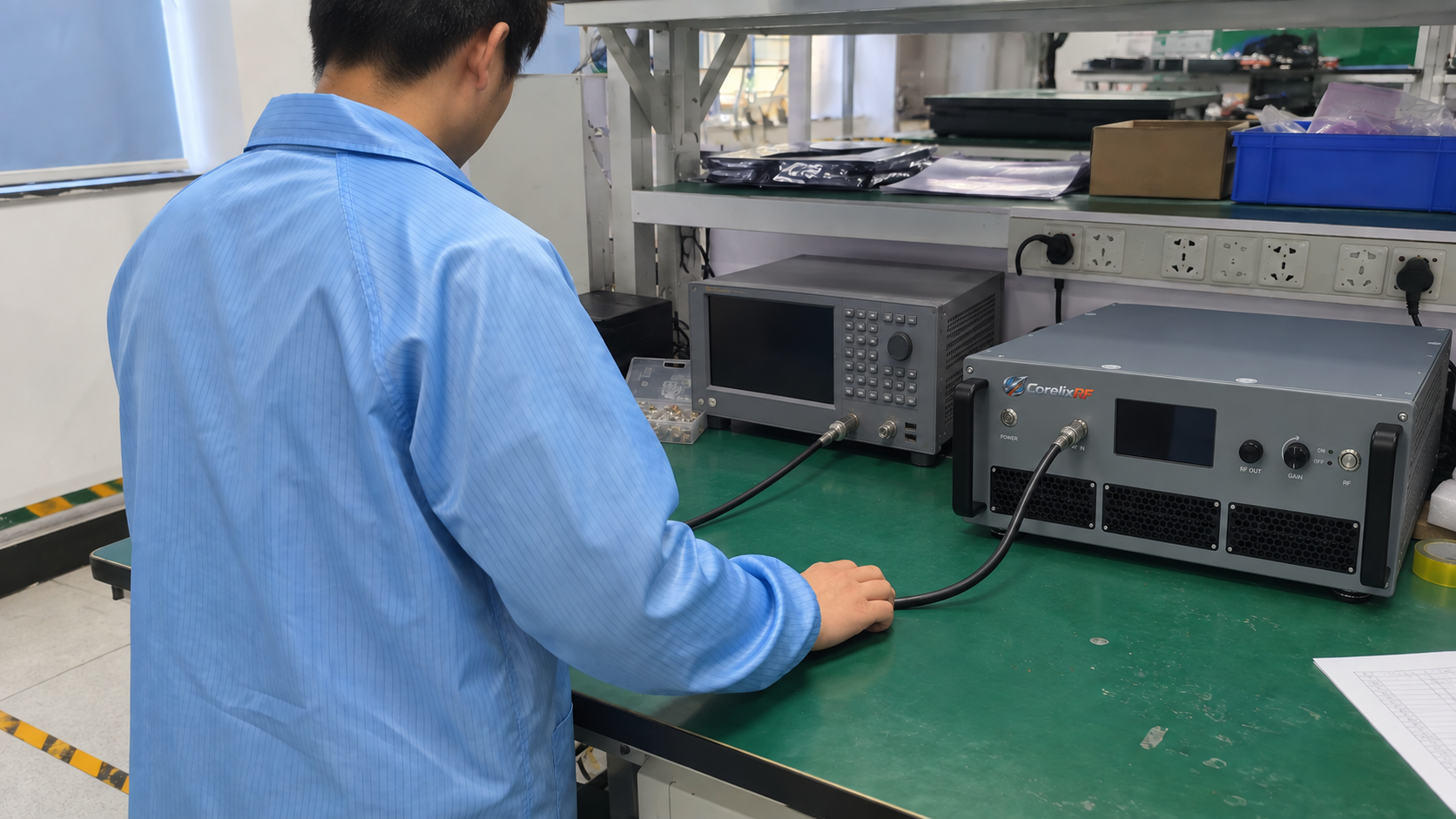
Keep device and system efficiency separate
Power-added efficiency, or PAE, uses RF output minus RF input, divided by DC input power. State which parts of the unit these figures cover. In contrast, DC-to-RF efficiency uses RF output divided by DC input.
For an AC-powered rack, an AC-input-to-RF figure includes losses and other loads within its measured boundary. Also state whether it includes drivers, fans and power conversion. Because these boundaries differ, a transistor’s peak PAE cannot stand in for rack efficiency.
Compare efficiency at the output your signal needs. A peak figure may come from a point that fails your distortion limit. The two CorelixRF examples here do not provide matched GaN vs GaAs efficiency tests. So you still need data for your waveform to compare the two materials.
4. What Must You Check for Power, Cooling and RF Ports?
Supply and heat removal
A DC-input unit needs a supply with the right voltage range and enough current. Check the wiring path as well. For an AC-input rack, follow the unit’s stated input needs. Its AC input rating does not state the voltage at a transistor inside.
Ask for input demand in each state you will use. However, RF output and supply voltage alone cannot tell you how much supply current to allow. You also need power-loss data and duty conditions to plan heat removal.
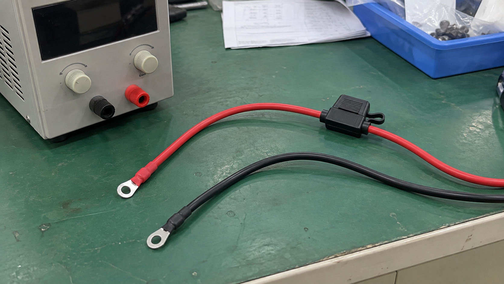
For forced-air units, check intake and exhaust space against the rack cooling requirements. A nearby unit may blow hot air into an intake even if the room feels cool. Also check airflow, ambient temperature and duty cycle. Rack height alone does not settle cooling needs.
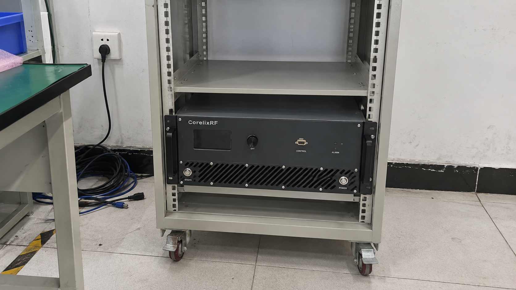
A 26.5–40 GHz rack-mount GaN example
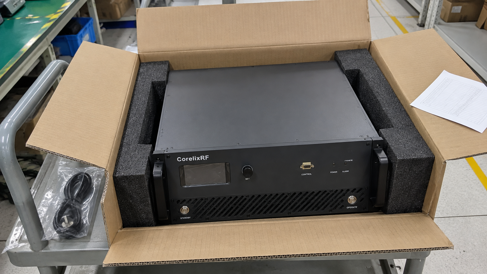
The CorelixRF CRF-PA-26500M40000M-40W datasheet states GaN, 26.5–40 GHz and 40 W output. The unit uses a 19-inch 4U rack housing, AC input and forced air. Its RF input is 2.92 mm female, and its output is WR28.
Both examples below use GaN. Their different bands and formats show what to check when you fit the unit. However, they do not prove a GaN vs GaAs performance advantage.
| Integration item | 6–18 GHz / 100 W, 28 V configuration | CRF-PA-26500M40000M-40W |
|---|---|---|
| Input supply | DC 28 V | AC 220 V ±10%, 50/60 Hz |
| Mechanical arrangement | 400 × 200 × 80 mm | 19-inch 4U rack-mount |
| Cooling method | Forced air | Forced air |
| RF input | SMA female | 2.92 mm female |
| RF output | N female | WR28 waveguide |
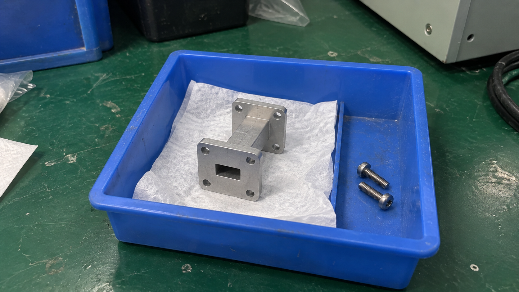
Check the stated coaxial and waveguide interfaces before you plan the RF path. For the WR28 output, confirm the mating parts and the path to your load. Also check each transition, cable or adapter for its own loss and power limits.
Then agree where you will measure output. Power at the amplifier port differs from power after a lossy cable or transition. Use the same reference plane in the quote and acceptance test.
5. Can a GaAs Driver Feed a GaN Output Stage?
A GaAs driver can feed a GaN output stage if their gain, drive, impedance and operating needs match. Each stage can use a different material. So a GaN vs GaAs choice need not apply to every stage in the RF chain.
Check the driver at the level needed by the final stage. If it compresses too much before reaching that level, it sends a distorted signal downstream. More output power from the final stage cannot restore the signal quality already lost.
Also check drive margin across your band and temperature range. Small-signal gain may differ from gain near full output. Include interstage loss when working out how much drive reaches the next stage.
For a whole unit, use its stated input needs and measured output data. However, do not infer its driver material from a GaN label. The two CorelixRF datasheets used here do not state what material their driver stages use.
6. What Does a GaN vs GaAs Choice Cost to Install?
Use one written brief when asking for prices. An offer for saturated power differs from one that commits to power at your distortion limit. Before comparing prices, check the band, operating mode and what comes with each unit.
If a unit needs extra support hardware, its purchase price is only part of project cost. Your setup may also need:
- A power supply and wiring.
- Cooling, rack space and mounts.
- RF cables, waveguide parts and adapters.
- Test fixtures, measurements and acceptance records.
- Work to fit and test the unit in your system.
Mark which parts the supplier provides and which your team must source. Then compare each format with the power, cooling and space you already have.
Typical curves help you assess a design, but acceptance needs agreed limits. State the test conditions and band points for those limits. If RF amplifier production testing forms part of acceptance, state which results must appear in each unit’s records.
Also ask for proof of service-life claims when they affect your choice. That proof must apply to the build and the way you plan to use it. Material choice alone does not prove how long a unit will last.
Keep open questions beside each quote. Then resolve gaps that could change usable output, the work to fit the unit or its acceptance tests. Do this before you select a model.
7. What Should You Put in the RFQ?
Your RFQ should let suppliers assess the same signal and output need. Make clear which limits are fixed and which can change. For an existing model, include its supply and housing details along with the model number.
| RFQ field | Information to provide |
|---|---|
| Frequency and bandwidth | Full operating range and instantaneous signal bandwidth |
| Required output | Power value, average or peak definition and measurement reference plane |
| Signal conditions | Waveform, peak-to-average ratio, CW or pulse operation, and applicable timing |
| Signal quality | EVM, ACLR, IMD or other relevant limits with test conditions |
| Efficiency | Required operating point and device, DC-input or AC-input measurement boundary |
| Installation | Available supply, cooling, dimensions, RF interfaces and environment |
| Acceptance | Required curves, test points, measurement conditions and pass criteria |
Add a system drawing or port sketch to show space and connection limits. If a value is still open, give a range you can accept. Suppliers can then see where their proposed model has room to differ.
Use one RFQ revision for the GaN vs GaAs review. Send later changes to every supplier so you can trace each quote to the right requirements.
Send your band, waveform, output conditions and installation needs through our RF amplifier inquiry form for configuration and quotation review.
Frequently Asked Questions
Q1. Does GaN always win a GaN vs GaAs efficiency test?
No. Efficiency depends on design, band, output and signal. It also depends on which parts you include in the test. So compare data at the point your system needs. Peak PAE does not show whole-system efficiency when you run a unit below that peak point.
Q2. When is GaAs still a suitable choice?
A GaAs model remains a choice if it meets your band, usable power and signal quality needs. It must also fit your system. This can include use as a driver stage. Compare its test data and project cost with other models before you decide.
Q3. Can rated power count as linear output power?
Only if the rating states the linear mode you need and data supports that claim. Otherwise, ask for results with your waveform and distortion limit. A model’s wattage or Psat figure alone does not supply that proof.
Q4. Does GaN need less cooling?
Heat loss, heat-flow paths, duty cycle and the environment set cooling needs. So check them for the whole unit at your planned output. A GaN label does not tell you required airflow, heatsink size or allowed temperature.
Q5. Can GaN directly replace GaAs?
For an RF amplifier replacement, match the new unit to your RF, electrical, thermal and mechanical needs. Check drive, gain, usable power, supply, ports and cooling under the conditions you plan to use. Confirm these for the exact build before you approve a swap.