
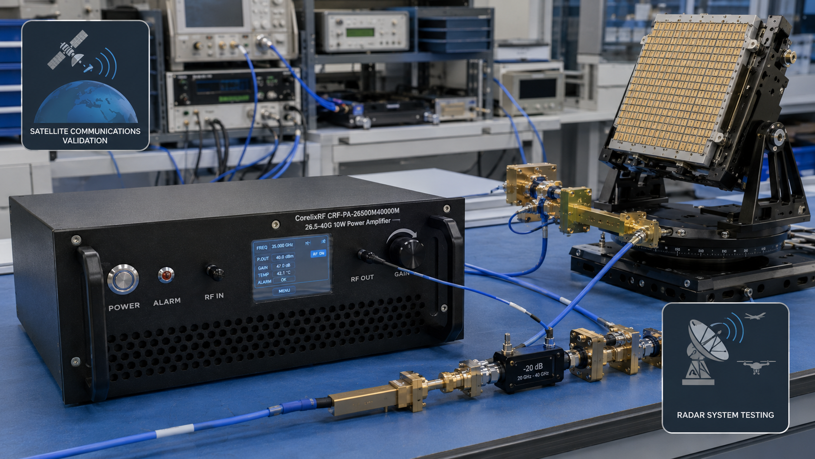
A 26.5-40 GHz solid-state power amplifier is chosen when a test bench moves into Ka-band and high-frequency microwave work where connector choice, fixture loss, measurement uncertainty, and mechanical integration become as important as output power. The local CorelixRF specification folder includes CRF-PA-26500M40000M variants from low-watt classes through higher-power versions including 100 W, 120 W, 160 W, 200 W, and 500 W filenames. That range gives engineers several possible starting points, but the final selection must be tied to the real test path.
This article is intentionally conservative. It does not claim a specific gain value, output flatness, or certification unless a current datasheet confirms it. Instead, it gives buyers a practical way to request the right review from CorelixRF.
Why 26.5-40 GHz Is Different From Lower-Frequency Selection
At solid-state frequencies, every transition matters. Cables, adapters, waveguide interfaces, connector torque, calibration plane, and fixture repeatability can change the result. A 26.5-40 GHz solid-state power amplifier should therefore be reviewed as part of the measurement chain, not only as a box with a frequency range and wattage.
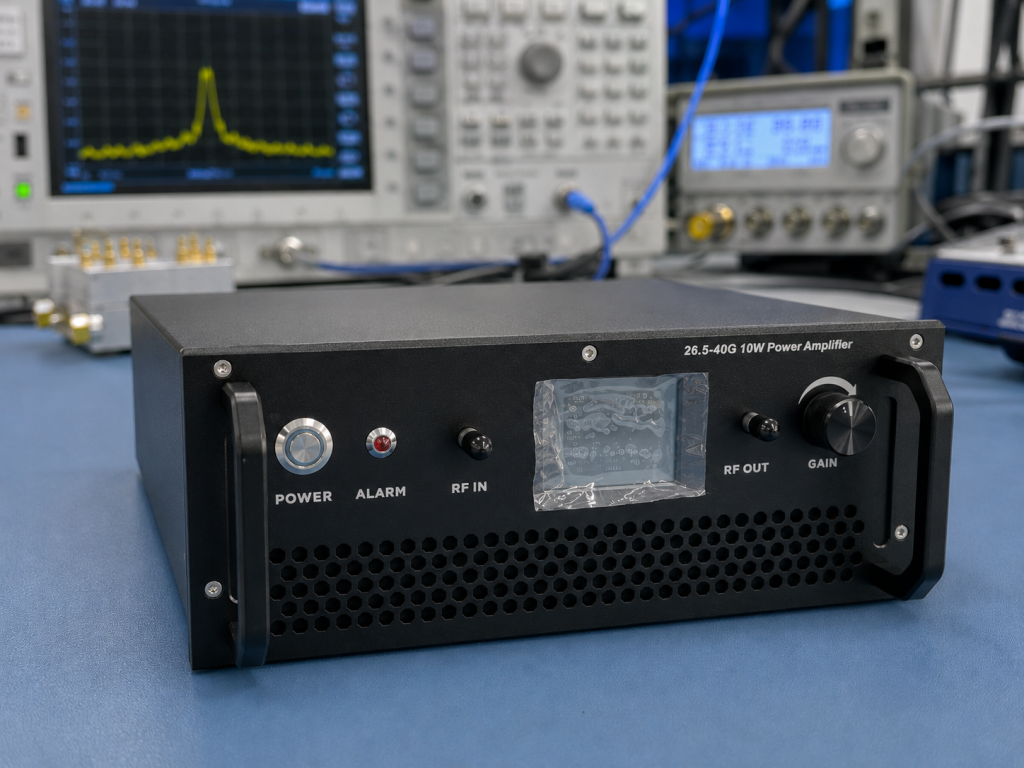
Ka-band benches are often used for module validation, front-end evaluation, satellite communications development, radar-related testing, and component stress screening. Each use case places different weight on output power, spectral behavior, thermal control, and physical layout. Engineers should describe the application without overstating confidential program details.
Define the Measurement Plane
Before requesting an amplifier, decide where output power must be achieved. Is it at the amplifier output connector, after a coupler, at the input of a device under test, or after a waveguide transition? The answer changes the required power class. At 26.5-40 GHz, even short interconnects and adapters can add meaningful loss.
For a production or qualification bench, also define how the output will be measured and verified. Include the power sensor range, calibration method, expected uncertainty, and any required test report format. This helps CorelixRF understand whether the amplifier is part of a simple lab chain or a more controlled validation environment.
Power Class Review
The local files indicate many CRF-PA-26500M40000M options, including 2 W, 5 W, 10 W, 25 W, 40 W, 50 W, 100 W, 120 W, 160 W, 200 W, and 500 W filenames. Lower-power units may be appropriate for component testing or gain-block support. Higher-power units may be needed when losses, field generation, or stress testing demand more delivered power.
The right choice depends on the required power at the measurement plane, allowed distortion, thermal profile, and system safety margin. If the bench includes switch matrices, long cables, isolators, or waveguide components, state those details in the RFQ. A wattage-only request can lead to unnecessary cost or insufficient margin.
Connector, Waveguide, and Mechanical Details
Ka-band integration should specify RF interface expectations early. Connector family, waveguide transition needs, rack space, airflow direction, and front-panel access can determine whether a standard product fits. If the amplifier will be moved between benches, connector robustness and repeatable setup procedures may matter. If it will live in a fixed rack, remote control and status readback may be more important.
CorelixRF can compare the requirement with its standard RF power amplifier platform options and determine whether a custom RF amplifier review is needed. The more complete the mechanical and control information, the faster that decision can be made.
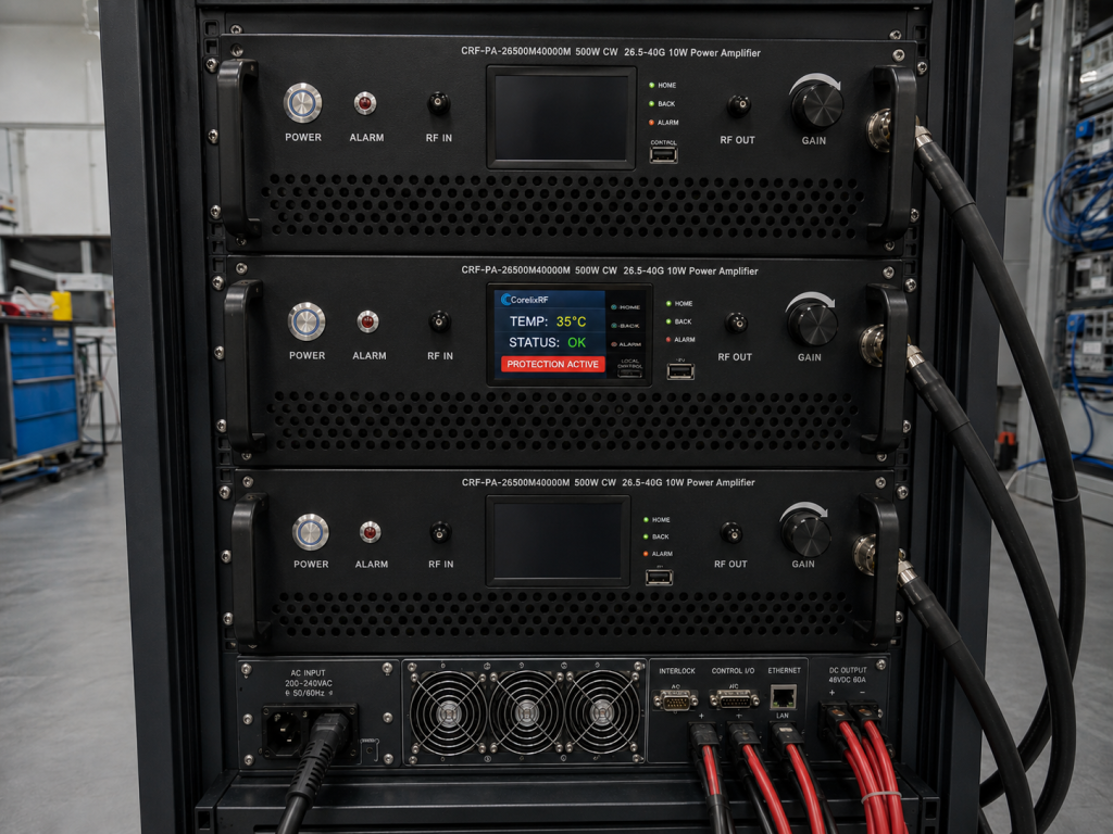
Thermal Behavior and Protection
High-frequency power amplifiers can produce substantial heat, especially in higher-power classes. The RFQ should define duty cycle, burst length, ambient temperature, rack airflow, and any requirement for continuous operation. It should also ask CorelixRF to confirm available protection and monitoring for the selected model, including fault indication and thermal handling.
Protection language matters because not every feature should be assumed across every configuration. Ask for confirmation of mismatch tolerance, output protection, temperature monitoring, and remote status options when those functions are important to the project.
A Practical Ka-Band RFQ Format
Use this short structure:
- Frequency range: 26.5-40 GHz or a narrower Ka-band window.
- Required output power and location of the measurement plane.
- Expected waveform, modulation, duty cycle, and run time.
- Interconnects, adapters, waveguide transitions, and known losses.
- Connector preference and mechanical/rack constraints.
- Control, monitoring, interlock, and documentation needs.
- Required test data and acceptance criteria.
This format helps both the engineering team and procurement team compare options without relying on vague requests. It also aligns with the type of application-note content that high-frequency buyers expect: practical integration guidance, not exaggerated performance claims.
FAQ
What CorelixRF 26.5-40 GHz power classes are visible locally?
The local CRF-PA-26500M40000M filenames include multiple classes from 2 W through high-power variants, including 100 W, 120 W, 160 W, 200 W, and 500 W. Current datasheets should be checked for final values.
Why does the measurement plane matter at Ka-band?
At 26.5-40 GHz, cables, adapters, couplers, and waveguide transitions can add meaningful loss. The required output must be defined at the point where the test actually needs power.
Should a buyer request a standard or custom amplifier?
Start with the closest standard platform, then request custom review if connector, enclosure, control, cooling, or documentation requirements do not fit.
What integration details should be included?
Include interface type, adapter or waveguide needs, rack space, airflow, duty cycle, control, monitoring, and acceptance-test requirements.