
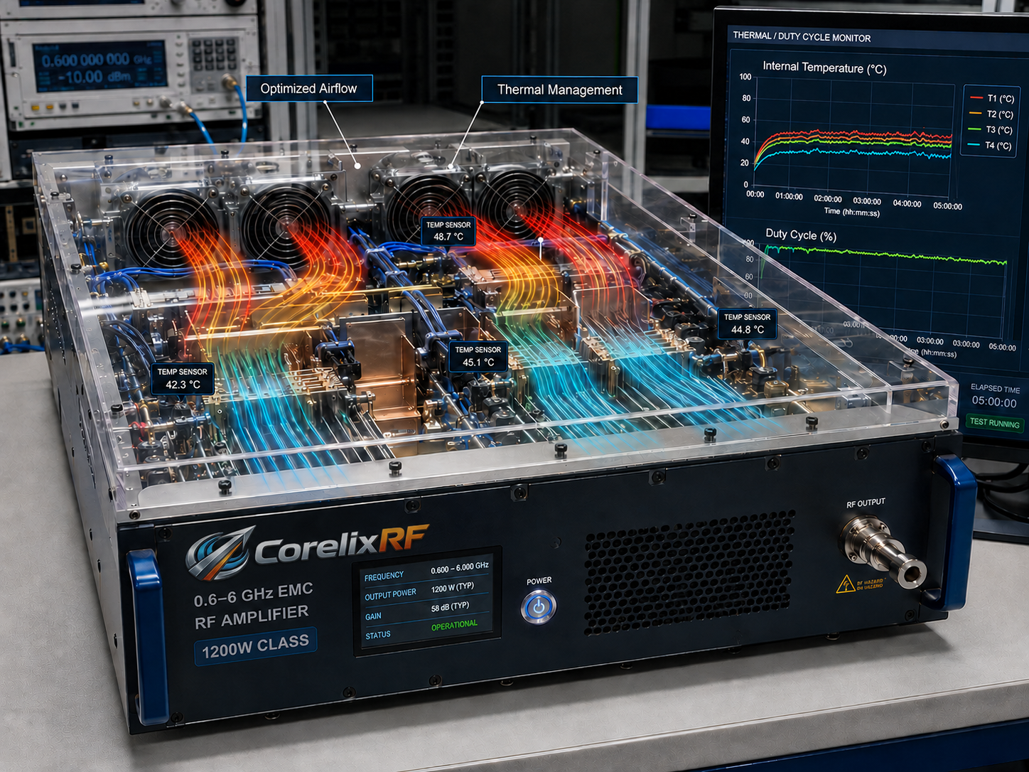
A 0.6-6 GHz EMC RF amplifier is usually purchased for a more demanding job than ordinary bench gain. It may support radiated immunity testing, broadband field generation, device stress screening, or pre-compliance work where the amplifier is one part of a calibrated RF path. The local CorelixRF library includes many CRF-PA-600M6000M datasheet filenames, with power classes ranging from tens of watts to higher-power variants such as 1000 W and 1200 W. That wide file set makes this topic important for buyers who need to choose power based on test level, chamber loss, antenna factor, and duty cycle.
This guide does not claim compliance to a specific standard or a guaranteed field strength. Those outcomes depend on the complete test setup. Instead, it explains how to prepare a clean amplifier requirement for CorelixRF review.
Treat EMC Power as a System Calculation
When specifying an 0.6-6 GHz EMC RF amplifier, do not start with the largest wattage available. Start with the field strength target, test distance, antenna behavior, cable loss, switch or coupler loss, modulation requirement, and dwell time. The amplifier output power is only one variable in the final field level.
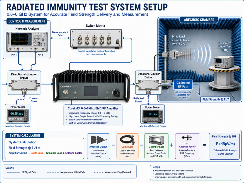
Radiated immunity systems can be especially sensitive to loss and mismatch. A small change in cable routing, antenna choice, or chamber setup can change required amplifier headroom. For that reason, the RFQ should state how the amplifier will be used, not just the frequency band and nominal watts.
Why 0.6-6 GHz Needs Careful Band Planning
The 0.6-6 GHz span crosses several practical frequency regions. Antenna performance, cable loss, and fixture behavior can change substantially across the band. An amplifier that is suitable for one segment may need careful review at another segment if the test level, modulation, or operating duration changes.
A good procurement package separates the must-have frequency range from optional coverage. If the lab only needs 0.8-4.2 GHz now but wants future expansion toward 6 GHz, state that. CorelixRF can then review whether a full 0.6-6 GHz platform is appropriate or whether another family better matches the immediate test case.
Power Classes and Margin
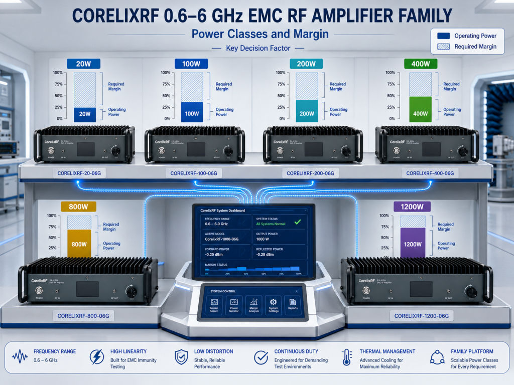
The local file list includes 20 W, 40 W, 50 W, 60 W, 80 W, 100 W, 150 W, 200 W, 250 W, 300 W, 400 W, 500 W, 600 W, 800 W, 1000 W, and 1200 W variants in the 0.6-6 GHz EMC folder. This does not mean every variant is the right fit for every test. It means CorelixRF has a broad set of documented product references for review.
Engineers should calculate required power using the actual setup and then add reasonable margin for aging, repeatability, and fixture variation. Procurement should also ask what test data can be supplied with the amplifier and how the output should be verified after installation. CorelixRF pages on RF testing and validation and manufacturing and engineering are relevant when documentation and production consistency matter.
Cooling and Duty Cycle for EMC Work
EMC tests can involve longer dwell times than quick bench demonstrations. That makes cooling a major selection factor. The RFQ should state the duty cycle, expected run time, ambient temperature, airflow restrictions, rack or chamber location, and whether the amplifier will run unattended during automated sequences.
Thermal design also affects service life and repeatability. A high-power amplifier installed in a crowded rack needs different attention than a lower-power amplifier on an open bench. If the test plan requires continuous or high-duty operation, describe it plainly so CorelixRF can review the suitable design approach.
Protection, Monitoring, and Safe Operation
EMC environments can expose an amplifier to changing loads and reflected power. Buyers should ask about mismatch behavior, over-temperature handling, input overdrive protection, and available fault indication. The safest procurement language is request-based: ask CorelixRF to confirm available protection and monitoring features for the chosen model rather than assuming every feature exists on every variant.
Remote control may also matter. Automated EMC systems often need amplifier enable control, status monitoring, and clear fault feedback. Define the desired control interface early, especially if the amplifier must integrate with existing chamber software or an internal test platform.
What to Send With the RFQ
A useful RFQ for a 0.6-6 GHz EMC amplifier should include:
- Required frequency range and any priority bands.
- Target field strength or delivered power requirement.
- Antenna, chamber, cable, switch, and coupler losses if known.
- Modulation type, dwell time, duty cycle, and test sequence.
- Desired power class or calculated minimum output power.
- Cooling environment and rack constraints.
- Control interface, monitoring, interlock, and protection needs.
- Required documentation, calibration support, and acceptance data.
If the requirement does not map cleanly to a standard product, ask for a custom RF amplifier review. That can be more productive than forcing a standard model into a test environment with unusual thermal, control, or mechanical constraints.
FAQ
What power range is visible in the local 0.6-6 GHz EMC filenames?
The local CRF-PA-600M6000M datasheet filenames include many classes from tens of watts up to high-power variants such as 1000 W and 1200 W. Final values must be confirmed against current datasheets.
Can an amplifier alone guarantee an EMC field strength?
No. Field strength depends on the amplifier, antenna, cables, chamber, test distance, modulation, and calibration process. The amplifier should be selected as part of the whole RF path.
Why is duty cycle important for EMC amplifier selection?
Longer dwell times and automated sequences can create sustained thermal load, so cooling and protection need to match the actual operating profile.
What should labs ask about protection?
Ask CorelixRF to confirm mismatch handling, over-temperature behavior, input protection, status readback, and any available remote fault reporting for the selected model.